Introduction
Breast cancer is one of the primary causes of the unwanted death of women throughout the world [Reference Mahmud, Islam, Misran, Almutairi and Cho1]. Early stage detection of malicious tumors is critical for the treatment and survival of the patient as there is no way to prevent cancer [Reference Heywang-Köbrunner, Schreer, Heindel and Katalinic2, 3]. Although X-ray mammography has been successfully applied for tumor detection, it has limitations such as low contrast between normal and cancerous tissues, false-negative and false-positive results, especially for young women with more dense breasts, ionizing radiation, and uncomfortable during the imaging [Reference Elmore, Barton, Moceri, Polk, Arena and Fletcher4]. Therefore, Microwave Imaging (MWI) systems have emerged as a complementary tool to improve the mentioned limitations in breast imaging systems [Reference Conceição, Mohr and O'Halloran5].
MWI systems can be classified into two categories: tomography-based and radar-based imaging. In the tomography-based method, detection and localization of the tumor are performed through analyzing scattered waves from the breast tissues and by solving a forward, and inverse scattering problem [Reference Conceição, Mohr and O'Halloran5]. In the radar-based imaging systems, on the other hand, an antenna (or an array of antennas) is used to transmit and receive ultrawideband (UWB) pulses by employing the transmitter T x and the receiver R x antennas at different locations around the breast phantom [Reference Ahadi, Isa, Saripan and Hasan6]. In this system, the position and size of the cancerous tumor can be detected by estimating the time delay between the transmitted and received signals. In general, data acquisition can be achieved via mono-static, bi-static, and multi-static array configurations [Reference Li, Davis, Hagness, Van der Weide and Van Veen7]. In the mono-static technique, transmitting and receiving are carried out via the same antenna, which the antenna can be physically repositioned over the exterior of the breast or fixed as an element of an antenna array. In the bi-static technique, each element (T x antenna) of the array radiates electromagnetic waves toward the breast sequentially while the rest of the elements record scattered signals at various angles from the T x antenna. In the multi-static systems, both acquired mono-static and bi-static signals are applied. Among these methods, the multi-static array configuration provides the most amount of information about the breast phantom [Reference Shao and McCollough8]. In order to estimate the location of the tumor, image reconstruction algorithms are applied. These algorithms are generally divided into data-dependent and data-independent beam-forming methods [Reference O'Loughlin, O'Halloran, Moloney, Glavin, Jones and Elahi9–Reference Mewara, Deegwal and Sharma11]. The confocal microwave imaging algorithm or delay-and-sum (DAS) method is a desirable and robust technique for tumor detection, which is the basis of the other algorithms to approximate the exact location of the tumor in the breast model [Reference O'Loughlin, Oliveira, Glavin, Jones and O'Halloran12].
The quality and the accuracy of the tumor detection rely on diverse observation data. Thus, the design of the antenna and antenna array configuration is crucial for the quality of the imaging system [Reference Ahadi, Isa, Saripan and Hasan6]. More distinct data can be collected by placing more antenna elements around the breast phantom [Reference El Misilmani, Naous, Al Khatib and Kabalan13]. The bandwidth, on the other hand, provides more range resolution. Therefore it is highly desirable to have a broadband compact antenna. Furthermore, because the conductivity of the breast tissues increases at higher frequencies, the antenna should operate at lower frequencies with acceptable signal penetration without exceeding SAR limits [Reference Benny, Anjit and Mythili10]. Another issue that hinders the efficiency of the imaging system is the reflection between air and breast tissues. Thus, most systems immersed their antennas inside a liquid medium [Reference Meaney, Fanning, Li, Poplack and Paulsen14–Reference Fasoula, Duchesne, Gil Cano, Lawrence, Robin and Bernard17] and some with a solid coupling shell to minimize strong reflection between the air–breast interference [Reference Preece, Craddock, Shere, Jones and Winton18, Reference Kuwahara19]. While some antennas contact directly with the breast without any coupling medium or in a wearable system [Reference Shao and McCollough8–Reference Benny, Anjit and Mythili10, Reference Porter, Coates and Popovic20, Reference Song, Sasada, Kadoya, Okada, Arihiro, Xiao and Kikkawa21], several air-coupled antennas with high gain performance have also been applied [Reference Islam, Mahmud, Misran, Takada and Cho22, Reference Islam, Samsuzzaman, Faruque, Singh and Islam23]. Various antennas have been proposed for the breast imaging systems, such as parasitic resonator-based UWB antennas [Reference Mewara, Deegwal and Sharma11, Reference Hossain, Islam, Almutairi, Singh, Mat and Samsuzzaman24, Reference Mahmud, Islam, Almutairi, Samsuzzaman, Acharjee and Islam25], low-profile aperture-stacked patch (ASP) antennas [Reference Mehranpour, Jarchi, Keshtkar, Ghorbani, Araghi and Khalily26], tunable UWB antennas [Reference Li, Zhai, Li, Liang and Han27], sensor-based UWB antennas [Reference Mahmud, Islam, Misran, Almutairi and Cho1], different types of Vivaldi antennas [Reference Fasoula, Duchesne, Gil Cano, Lawrence, Robin and Bernard17, Reference Hasim, Ping, Islam, Mahmud, Sahrani, Mat and Zaidel28–Reference Selvaraj, Srinivasan, Kumar, Krishnan and Annamalai31], directional UWB antennas [Reference Porter, Coates and Popovic20, Reference Islam, Mahmud, Islam, Kibria and Samsuzzaman32], coplanar waveguide UWB antennas [Reference Islam, Islam, Faruque, Samsuzzaman, Misran and Arshad33, Reference Mahmud, Islam, Misran, Kibria and Samsuzzaman34], electromagnetic bandgap-based UWB antennas [Reference Islam, Samsuzzaman, Islam and Kibria35] and polarized-UWB antenna arrays [Reference Jafari, Deen, Hranilovic and Nikolova36, Reference Porter, Kirshin, Santorelli, Coates and Popović37]. In addition to these studies, commercial systems have also been built with different antenna designs including ASP antennas [Reference Kuwahara19, Reference Klemm, Craddock, Leendertz, Preece and Benjamin38], slot antennas [Reference Song, Sasada, Kadoya, Okada, Arihiro, Xiao and Kikkawa21, Reference Gibbins, Klemm, Craddock, Leendertz, Preece and Benjamin39], antipodal Vivaldi antennas [Reference Fear, Bourqui, Curtis, Mew, Docktor and Romano40, Reference Bourqui, Okoniewski and Fear41], and flexible microstrip antennas [Reference Porter, Bahrami, Santorelli, Gosselin, Rusch and Popović42]. However, most of the mentioned antennas for breast cancer detection do not cover lower frequencies and have low fractional bandwidth. Generally, to achieve a robust system, it is indispensable to design an antenna with a compact size, wideband, and good radiation performance. Typically, planar antennas are the most favorite types of antenna in microwave breast imaging due to their compact size, broadband properties, ease of design, and fabrication. Furthermore, having sufficient penetration into the breast tissues (especially low-adipose tissues) is desirable. Thus, the design of a compact size antenna that radiates at a lower frequency (around 1 GHz) is particularly important.
In this paper, a compact wideband SPA is presented for the reasons mentioned previously. The proposed antenna has a unique operational frequency, safety, and near-field radiation properties. The proposed antenna operates from 0.9 to 9.6 GHz with an excellent fractional bandwidth of 165$\%$ , thus achieving both wideband and low working frequency goals. In order to reduce the reflections from the breast tissue and achieve miniaturization of the antenna [Reference Epstein, Golnabi, Meaney and Paulsen43, Reference Bourqui, Kuhlmann, Kurrant, Lavoie and Fear44], the antenna is designed and optimized inside a coupling medium with dielectric permittivity of 9 and conductivity of 0.4 S/m, which is close to the average value of the dielectric properties of breast tissues at the center of operating frequency (5 GHz) [Reference Klemm, Craddock, Leendertz, Preece, Gibbins, Shere and Benjamin45]. The near-field characteristics of the antenna adjacent to the breast model have been simulated and analyzed. Finally, an antenna array consisting of 31 antennas is formed to reconstruct an image of a spherical tumor with a diameter of 5 mm placed inside the breast phantom.
This paper is organized as follows: Section “The proposed slotted patch antenna” will present the antenna design and its performance. The proposed antenna for breast cancer detection applications and image reconstruction method will be detailed and discussed in Section “The proposed antenna performance for breast tumor detection application,” followed by the conclusion in Section “Conclusion.”
The proposed slotted patch antenna
Antenna design
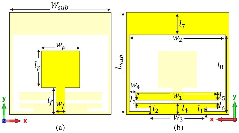
As mentioned, the antenna element plays a crucial role in the quality of the overall MWI systems. In particular, for breast tumor detection purposes, the antenna is required to be compact, and broadband [Reference Mahmud, Islam, Misran, Almutairi and Cho1]. While antenna compactness increases the number of antennas that can be placed on the system, thus allowing the system to extract more distinct data, antenna bandwidth, on the other hand, increases the resolution of the system. Although the attenuation increases with frequency and lower frequencies are desirable for antenna operation, several works have been proposed for the breast imaging system that increases penetration rate by applying field focusing technique at millimeter-wave (mm-wave) frequencies [Reference Di Meo, Matrone and Pasian46, Reference Iliopoulos, Di Meo, Pasian, Zhadobov, Pouliguen, Potier, Perregrini, Sauleau and Ettorre47]. Typically, 1–9 GHz band is used for microwave breast tumor detection purposes [Reference Islam, Mahmud, Misran, Takada and Cho22, Reference Shao and Adams48–Reference Jalilvand, Li, Zwirello and Zwick50]. Furthermore, to improve the system's matching and reduce unwanted reflections, antennas are typically designed inside a coupling medium, which can significantly alter the antenna behaviors. The antenna design for microwave breast imaging becomes particularly challenging with the above requirements. Printed antennas are good candidates for MWI systems and are commonly used by researchers [Reference Chen and Chia51] due to their broadband characteristics, compactness, and ease of fabrication. This study proposes an SPA with the added parasitic elements on the ground plane. The proposed antenna configuration is shown in Fig. 1 that all antenna dimensions are given in the caption. The antenna is designed on a low-cost FR4 substrate with a relative permittivity εr = 4.3, a loss tangent tanδ = 0.025, and a substrate thickness of 1.6 mm in the CST microwave studio simulator [52]. The antenna has a very compact size of 16 × 16 mm2 that is simulated inside a 40 × 40 × 40 mm3 coupling medium box. The coupling medium is modeled with a relative permittivity of 9 and conductivity of 0.4 S/m, similar to normal breast tissue at the center of operating frequency according to the instructions in [Reference Klemm, Craddock, Leendertz, Preece, Gibbins, Shere and Benjamin45, Reference Byrne, Sarafianou and Craddock53, Reference Byrne and Craddock54].
Geometry of the proposed SPA: (a) front view and (b) back view. Design parameters (all in mm) are given as: H sub = 16, L sub = 16, w p = 6, l p = 5.8, l f = 4.2, w f = 1.4, W 1 = 13, W 2 = 15, W 3 = 8.4, W 4 = 1, L 1 = L 2 = L 3 = 0.5, L 4 = 1.75, L 5 = 1.25, L 6 = 0.75, L 7 = 3.5, and L 8 = 12.

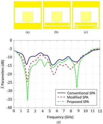
The reason behind the selection of slot antenna for breast cancer detection systems is due to its good radiation performance in the microwave breast imaging applications [Reference Gibbins, Klemm, Craddock, Leendertz, Preece and Benjamin39]. The design steps of the proposed antenna are illustrated in Figs 2(a)–2(c) with the corresponding S 11 results in Fig. 2(d). Figure 2(a) depicts the conventional SPA. This slotted patch has three rather weak resonances at 1.8, 5.2, and 8.7 GHz bands. Figure 2(b) shows the antenna where a rectangular strip is added to the ground plane layer. As shown in S-parameter results in Fig. 2(d), the addition of a strip improves the matching of the antenna for the entire bandwidth via strengthening the resonances of the SPA. Finally, a pair of L-shaped sleeves were added and optimized in the ground plane to increase both the matching and the bandwidth of the antenna, which is shown in Fig. 2(c). The simulated reflection coefficient for the proposed antenna covers the frequency range between 0.9 and 9.6 GHz with an excellent − 10 dB fractional impedance bandwidth (FBW) of 165%. The proposed antenna exhibits MWI systems’ desired compactness and broadband characteristics.
Antenna evolution: (a) conventional SPA, (b) modified SPA, (c) the proposed SPA, and (d) comparison of the simulated reflection coefficients for the three antennas. The antennas are simulated inside a coupling medium as described in the text.

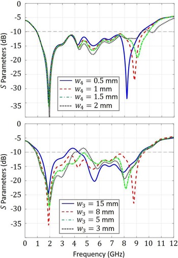
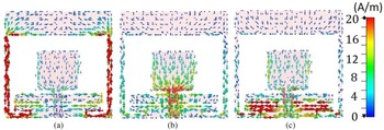
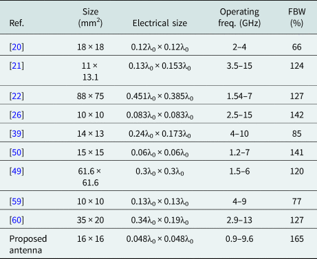
In addition, in order to understand the effects of added parasitic elements on the antenna performance, we have conducted parametric studies. Figure 3 shows the S 11 results for various values of W 3 and W 4. As can be seen from Fig. 3(b), the length of the sleeve W 3 has a significant effect on the matching of the antenna in the entire frequency range. The length of the strip W 4, on the other hand, can be used to control the higher frequency resonance, as can be seen from Fig. 3(a). To enhance our understanding of the working principle of the proposed antenna, the surface current distributions are shown in Fig. 4 at 1.9, 5.5, and 8.7 GHz, respectively. As can be seen from the figure, while the slot length primarily affects the lower resonance frequency, W 4 contributes to the resonances at all frequencies, and W 4 particularly strengthens the higher resonance. The comparison of the proposed antenna with other studies in the literature is summarized in Table 1 and will be further discussed in the “Conclusion” section.
Simulated reflection coefficient characteristics for different values of W 4 and W 3.

Simulated surface current distributions for the proposed SPA at three different frequencies: (a) 1.9 GHz, (b) 5.5 GHz, and (b) 8.7 GHz.

Comparison of the proposed antenna with other breast cancer imaging antennas when the λ0 is free space wavelength at the lower frequency

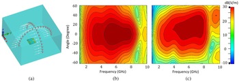
The antennas are typically placed very close to the breast in microwave breast tumor detection applications. Thus, near-field radiation is often preferred to investigate the radiation characteristics of the antenna. In order to investigate this characteristic, the received signals at sampled points at cross arcs in the distance of 40 mm far away from the front face of the antenna inside the coupling medium are measured. The evaluation is performed using the probes in the simulation environment as illustrated in Fig. 5(a). Figures 5(b) and 5(c) demonstrate the results of the received signals from the antenna at xz-plane (E-plane) and yz-plane (H-plane), respectively, which justify the near-field performance of the proposed antenna. As it can be seen in the figure, the fields are radiated symmetrically around the boresight (θ°) direction in the E-plane, while a squint is developed from 5 to 10 GHz in the H-plane. It may be due to the asymmetrical structure of the antenna regarding the feeding point in the H-plane.
(a) Cross arc probes in the front face of the proposed antenna in the simulation environment for E-plane (xz plane), and H-plane (yz plane), (b) the simulated E-plane and (c) H-plane of the proposed antenna inside the coupling medium.

Coupling medium
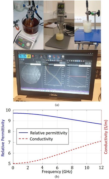
As mentioned, in order to have a lower reflection between the antennas and the breast phantom model, a coupling medium is often employed for breast tumor detection applications. For that, the relative permittivity of the coupling medium is chosen close to the permittivity of the fat tissue. With that, the proposed antenna has been designed and optimized inside a coupling with a relative dielectric permittivity of 9 in the previous section. In order to characterize the proposed antenna experimentally, the coupling medium was fabricated in the laboratory with a specific mix of Beeswax, water, and liquid paraffin. The fabrication procedure of the coupling medium is realized according to [Reference Henriksson, Gibbins, Byrne and Craddock55] and is displayed in Fig. 6(a). Dielectric parameters of the designed coupling medium are measured by a Dielectric assessment kit-3.5 probe (DAK-3.5) that consists of a handhold VNA Agilent N2352A FieldFox, and a computer with corresponding software. Due to the differences in liquid paraffin samples, the ratio of the paraffin and water is changed until the desired relative permittivity values are obtained. The measured relative permittivity and conductivity values of the designed coupling medium are shown in Fig. 6(b).
(a) Fabrication procedure and (b) measured relative permittivity and the conductivity of the coupling medium by the DAK-3.5 kit probe.

Experimental results
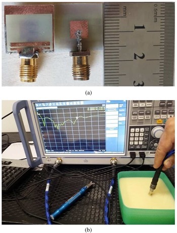
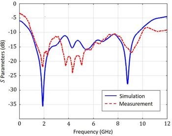
Next, the proposed antenna was fabricated on an FR-4 substrate, and an LPRS SMA connector was applied to excite the proposed antenna with the 5 mW input power as illustrated in Fig. 7(a). Figure 7(b) displays the measurement setup that was performed with the Rohde & Schwarz Vector Network Analyzer (100 kHz–20 GHz) when the antenna was fully immersed in the coupling medium. Consequently, the comparison of the simulated and measured reflection coefficients is illustrated in Fig. 8. Overall, a very good agreement is observed between the simulated and measured results. The proposed antenna has a measured − 10 dB bandwidth from 0.92 and 10 GHz.
(a) Front and back views of the fabricated antenna and (b) measurement setup of the antenna when fully immersed in the coupling medium.

Comparison of the simulated and measured reflection coefficient characteristics inside the fabricated liquid coupling model.

The proposed antenna performance for breast tumor detection application
The breast model and simulation setup
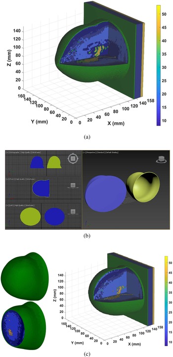
In order to evaluate the performance of the proposed antenna for breast cancer detection, a realistic breast model is employed in the simulation environment. Our basic breast model is the magnetic resonance imaging (MRI)-derived anatomically breast model (ACR class II) from the University of Wisconsin-Madison MRI breast cancer repository [56], which is classified as a scattered fibroglandular tissue breast model. The ACR class II model is shown in Fig. 9(a) at 5 GHz, while the color bar displays the relative permittivity of each tissue. In our system, we applied a table-based setup while the patient is lying in a prone position and her breast is inserted in a hemispherical breast housing according to the details in [Reference Byrne and Craddock54, Reference Mehranpour, Jarchi, Keshtkar, Ghorbani, Araghi, Yurduseven and Khalily57]. The overall radius of the breast housing is chosen to be 60 mm. Supposing that the breast model is fitted fully into the breast housing during the screening, it is required that the model be mapped to a hemispherical profile. Therefore, we can claim that the results that will be obtained in the simulation setup realize the results of the realistic environment [Reference Byrne and Craddock54]. In order to map the basic breast model in Fig. 9(a) to the mentioned hemispherical breast housing, the applied technique in [Reference Mehranpour, Jarchi, Keshtkar, Ghorbani, Araghi, Yurduseven and Khalily57] is used here. The sketched 3D CAD models of the skin layer and the internal environment of the modified breast model in Autodesk 3ds Max Software [58] environment are displayed in Fig. 9(b). The thickness of the skin layer is selected to be 1.5 mm uniformly at both breast and pectoral regions regarding the basic model in [56]. The modified ACR class II breast model at 5 GHz is illustrated in Fig. 9(c).
(a) ACR class II model which is used as the basic breast model. (b) The sketched 3D CAD models of the skin layer (yellow color) and internal environment of the modified breast model (blue color) in Autodesk 3ds Max Software. (c) The applied breast model.

Configuration of the antenna array
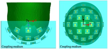
Next, a hemispherical antenna array encircling the breast phantom is constructed as depicted in Fig. 10. Note that the antennas are modeled inside the coupling medium modeled as a hemisphere with a total thickness of 20 mm. The distance between the antenna elements and the skin layer is chosen as 10 mm. Considering the antenna size and the area of the hemisphere, we were able to place a total of 31 antennas around the breast phantom for improved information. Furthermore, the arrangement of the antenna elements are done to minimize the polarization losses between the elements. With that, one antenna is placed in the center of the hemisphere. In the first row, six antenna elements with a 60°C angle difference, while the second and third rows consist of 12 antenna elements with a 30°C angle difference between the self-central points of each antenna. The difference angle between the single top antenna with the next rows is selected to be 22.5°C uniformly.
Configuration of antenna array around the applied breast model.

Image reconstruction
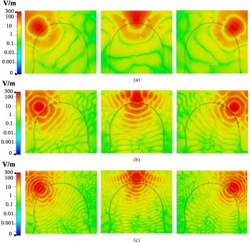
In order to prove the performance of the proposed antenna for breast tumor detection, the antenna array is constructed in the simulation environment as depicted in Fig. 10. It is important that the received signal has enough strength to reconstruct the high fidelity images of the tumor. Here, we study the electric field behavior inside the breast model. Figures 11(a)–11(c) show the E-field distributions inside the inhomogeneous breast model at 1.5, 2, and 6 GHz, respectively. There is an acceptable signal strength at all frequencies that reaches the chest. Simulated results show good signal strength at the selected frequencies showing the proposed antenna has a good near-field radiation characteristic close to the breast model. Furthermore, a tumor with a diameter of 5 mm is immersed inside the breast phantom. For this particular study, the tumor is placed inside the glandular tissue with the exact location of (x = 0 mm, y = 30 mm, z = 35 mm) regarding the system coordinate of the simulation setup in Fig. 10. Then, a multi-static radar-based imaging approach is employed to identify the location of the tumor [Reference Mehranpour, Jarchi, Keshtkar, Ghorbani, Araghi, Yurduseven and Khalily57]. Since with N elements array, a number of available monostatic and bistatic time-domain signals will be N and N(N − 1)/2, respectively [Reference Klemm, Leendertz, Gibbins, Craddock, Preece and Benjamin61]. Consequently, a number of 496 time-domain signals from the 31 elements are gathered in the simulation environment. After obtaining the recorded signals, initially, a calibration method is applied according to [Reference Mehranpour, Jarchi, Ghorbani and Keshtkar62] in order to eliminate the effects of the coupling medium and the skin. Following the calibration, an improved DAS algorithm [Reference Conceição, Mohr and O'Halloran5, Reference Mehranpour, Jarchi, Ghorbani and Keshtkar62] is utilized to reconstruct two-dimensional (2D) and three-dimensional (3D) images using the following equation:

where I(P f) is the energy of each scanning focal points, P f within the breast model, τ(p f) is the time-delay corresponding to each focal point, which is calculated based on the approximated wave speed between each T x and R x antennas [Reference Conceição, Mohr and O'Halloran5], w m is applied as a weighting factor to compensate the path-dependent attenuation along T x–R x paths with respect to tissue losses [Reference Dove63], τp is the integration window which is usually considered a percentage of the excitation pulse width, and M is the total number of available time-domain calibrated signals X m regarding T x–R x paths.
Simulated normalized electric field distribution for three different antenna excitation at (a) 2 GHz, (b) 5 GHz, and (c) 8 GHz.

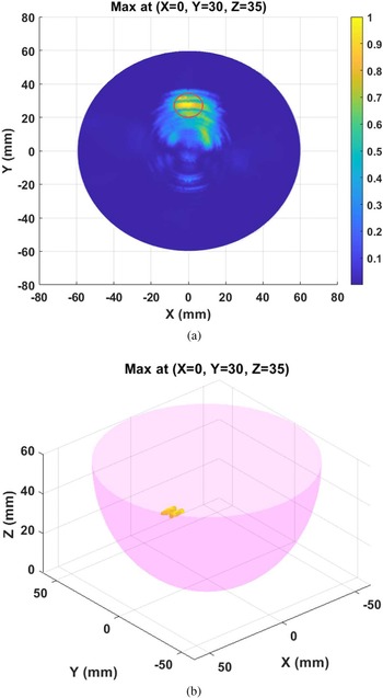
Figures 12(a) and 12(b) illustrate the 2D and 3D reconstructed images of the tumor. The location of the tumor is also indicated as a red circle in Fig. 12(a) that shows the intensity of the reconstructed image with good accuracy. In Fig. 12(b), the 3D images are formed and displayed so that the tumor can be detected precisely. Finally, in order to investigate the performance of the designed system, quantitative metric values, signal/mean ratio (SMR) and signal/clutter ratio (SCR) for the resulted images according to [Reference Conceição, Mohr and O'Halloran5, Reference Mehranpour, Jarchi, Keshtkar, Ghorbani, Araghi, Yurduseven and Khalily57] are calculated. Generally, the SMR parameter compares the mean of the backscattered energy over the tumor area to that of the backscattered energy over the whole breast tissues. Also, the SCR parameter specifies the peak value of the backscattered energy over the tumor area to that of clutter in the imaging region. The SMR and SCR parameters are 9.93 and 2.04 dB, respectively for the proposed system.
(a) 2D reconstructed image from a tumor which is positioned at (X = 0 mm, Y = 30 mm, Z = 35 mm) inside of the constructed breast model, and (b) 3D reconstructed image from the detected tumor.

Conclusion
This paper studies a compact SPA for MWI of breast tumor. Antennas for breast tumor imaging are required to be compact and broadband in order to allocate more antennas in a limited space and obtain better resolution. Furthermore, a coupling medium is typically used for these applications to reduce the reflections between the air and biological tissues. With these, an SPA is designed and optimized inside a coupling medium. The proposed antenna works between 0.9 and 9.6 GHz, with high fractional bandwidth of ~165%. To achieve this goal, a rectangular parasitic structure is applied on the ground of the ordinary SPA. Furthermore, a pair of sleeve structures are added to the ground plane to create an additional current path to enhance the bandwidth. Both the coupling medium and the antenna are fabricated and experimentally tested. Both simulation and experimental results agree very well. Table 1 compares the proposed antenna with some of the antennas in literature for breast cancer detection inside the coupling medium. The proposed antenna achieves a very compact size of 0.048λ × 0.048λ, where λ is chosen based on the lower frequency. Reduced electrical size allows one to locate more antennas around the breast phantom, thus obtaining more information from the measurement. The proposed antenna exhibits the desired characteristics of MWI for breast tumors. Finally, an accurate tumor detection with the proposed antenna array by using an improved confocal imaging algorithm has been illustrated.
 Mahdi Salimitorkamani received his B.Sc. degree in electrical engineering from Islamic Azad University, Iran, and his M.Sc. degree in electronic engineering from Gazi University, Ankara, Turkey. He is currently pursuing his Ph.D. degree in electrical engineering from Eskisehir Osmangazi University (ESOGU), Eskisehir, Turkey. His research interests include microwave and radar imaging, antennas and propagation, metasurface antennas, reconfigurable structures, implantable antennas, and electromagnetic theory.
 Mehdi Mehranpour received his B.Sc. degree in electrical engineering from Tabriz University, Tabriz, Iran, his M.Sc. degree in telecommunication engineering from Urmia University, Urmia, Iran, and his Ph.D. degree in telecommunication engineering from Imam Khomeini International University, Qazvin, Iran. His research interests include microwave and radar imaging, numerical methods in electromagnetics, phased arrays, antennas and propagation, metasurface antennas, reconfigurable structures, radar systems, signal processing, machine and deep learning methods for biomedical applications, and electromagnetic theory.
 Hayrettin Odabasi received his B.Sc. degree in electrical engineering from the Gebze Institute of Technology, Gebze, Kocaeli, Turkey in 2005, his M.S. degree in electrical engineering from Syracuse University, Syracuse, New York, USA in 2008, and his Ph.D. in electrical engineering from The Ohio State University, Columbus, Ohio, USA in 2013 respectively. From 2013 to 2015, he was a postdoctoral associate at Duke University, Durham, North Carolina where he worked on the development frequency selective metamaterial-based microwave imaging systems. Since 2016, he has been an assistant professor of Electrical and Electronics Engineering at Eskisehir Osmangazi University, Odunpazari, Eskisehir, Turkey. His current research interests include metamaterials and their applications, transformation optics, antenna design and characterization, and microwave imaging.