NOMENCLATURE
- (ai , bi , ci )
-
parameters to describe the characteristic of each straight line
- A
-
symmetric positive definite matrix
- B
-
normalised second central moments to compute A
- ID
-
index of matched prototype image to the query image
- n
-
total number of the fitting straight lines
- RANSAC
-
RANdom Sample Consensus algorithm
- S
-
prototype database
- α
-
pitch angle
- β, λ
-
angles between the aerofoil branches of the skeleton and the horizontal direction
- σ
-
threshold to determine the aircraft's longitudinal axis
- φ
-
counter clockwise orientation of an equivalent ellipse's major axis relative to the vertical axis
- Ω
-
extracted skeleton structure
Greek symbols
1.0 INTRODUCTION
Runway excursions such as takeoff overrun, takeoff veer-off, landing overrun and landing veer-off have become the most common accident type for commercial aircraft, covering 70% of aviation accidents in the world(Reference Van Es1,Reference Pavlin and Bračić2) recently. Such accidents will not only cause loss due to the damage on aircraft and other objects struck by the aircraft, but also threatens lives on board and the surrounding areas. Effective prediction of such accidents is an urgent problem to be solved.
Since the poses of aircrafts during taking off or landing gives much information about the aircrafts’ flight states, accurate pose estimation can effectively predict the aircrafts’ flight safety. The pixel-based ground monitoring system(Reference Dumont, Berthiaume, Laurent, Debaque and Prévost3) has been used to supervise the takeoff and landing performance of an aircraft in the airport, the key task of which is the accurate estimation of the flight pose parameters.
Actually, the pose estimation has always been one of the research hotspots in computer vision area and has wide applications such as bin picking(Reference Ou, Liu and Su6,Reference Xu, Wand, Zhang and Hua7) , medical diagnosis(Reference Zuffi, Learndini, Catani, Fantozzi and Cappello8,Reference Robinson, Tagara, Duncan and Jaffe9) and image registration(Reference Leng and Sun10-Reference David, Daniel, DuraiswamI and Samet15). One ambitious idea is to estimate objects’ pose parameters in 3D space from their 2D images, which generates the classical Perspective-n-Point problem(Reference Shan, Ji and Zhou16). Many algorithms(Reference Gao, Hou, Tang and Cheng17-Reference Lu, Hager and Mjolsness19) have been proposed to solve this problem and successfully obtain high-angle resolution. However, these algorithms all assume the correspondences between model points and image points are known, although the correspondences are very difficult and time-consuming to set up.
Therefore, researchers begin to study the pose estimation directly between 2D objects. Feature matching is a key issue for this problem, which however is quite different from the common key-point matching problem. Lowe's SIFT (Scale Invariant Feature Transform)(Reference Lowe20,Reference Lowe21) descriptor is one of the most effective features in key-point matching, with which one could find out the prototype image most similar to the query image. This kind of matching can recognise objects in a cluttered scene but is unable to represent the objects’ structure information. Therefore, it cannot effectively describe the relationship between parts among the object. To conquer this problem, many novel methods have been proposed to describe the objects’ structure information in the image domain. Ou(Reference Ou, Liu and Su6) makes use of the bilinear model to separate the pitch information and the yaw information by projecting the image in the horizontal and vertical directions respectively, and computes the minimum Euclidean distanceFootnote 1 between the extracted feature vectors of the prototype image and the query image to identify the angles of the query image. Since this method loses space information about the object, it is more appropriate to estimate the pose of the objects only rotating on the image plane. Soderberg(Reference Robert and Klas22) describes a low-dimension feature vector named the tensor doublet, which is realised by first extracting the corner information of an object in the image using the fourth-order tensor. Then pairs of tensors are chosen to construct a 6-dim vector, which represents the estimated pose, scale, position and rotation of the object. Finally, the feature matching process is finished by computing the distance between feature vectors. However, the maximal and minimal distances for a pair of features are difficult to choose, which will have significant influence on the estimation result.
This paper presents a novel geometry structure feature to estimate the pose of commercial aircrafts in a runway end safety area. We first extract the skeleton of the aircraft. Then the orientation features of fuselage and aerofoils of the aircraft are computed using the RANdom Sample Consensus (RANSAC) algorithm and the information of central moments. Since the features are extracted in different ways and have different properties, a two-step feature matching algorithm based on the proposed geometry structure feature is designed to measure the similarity between the prototype image and the query image. This similarity measure can independently estimate the roll angle and pitch angle of an aircraft; therefore, the estimation of the roll angle and pitch angle will not affect each other so as to maximise the discriminability of the similarity measure between features. In experiments, the simulated database consisting of different poses of two common types of aircrafts in Asia are used to validate the accuracy of the proposed geometry structure feature and the effectiveness of the two-step feature matching algorithm, which gives satisfactory results.
The rest of the paper is organised as follows: The pre-processing is introduced in Section 2 to distil the structure information of an aircraft. The pose estimation including pitch and roll information are extracted in Section 3, and then a two-step feature matching algorithm is designed in Section 4. The experiments are shown in Section 5. The conclusion and discussion comprise Section 6.
2.0 PRE-PROCESSING TO EXTRACT STRUCTURE INFORMATION
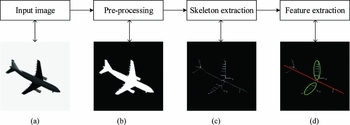
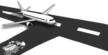
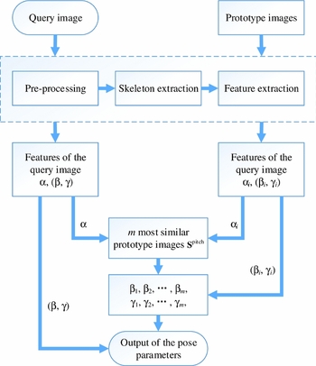
The main steps of the proposed method is shown in Fig. 1. When an aircraft is landing or taking off as illustrated in Fig. 2, its pose parameters will be in the allowable ranges. Therefore, by comparing the pose parameters of an aircraft with the pre-obtained pose parameters, we can effectively predict the aircraft's flight state. It is assumed in this paper that we have obtained the aircraft's 2D projection image just as shown in Fig. 1(a), and therefore the main task will be to effectively and efficiently estimate the aircraft's pose from its 2D image.
The extraction process of the proposed geometry structure features. (a) The input 2D projection image. (b) The segmentation result of (a). (c) Extraction of the aircraft's skeleton. (d) The proposed geometry structure features.

Illustration of where a camera is located during an aircraft's landing or takeoff to capture its 2D projection image.

Comparing with other common descriptors such as SIFT, HOG, etc., skeletons can globally describe objects’ structures, especially for those with many branches. Since the parts of an aircraft are rigidly connected with each other, the skeleton can effectively represent the structure of an aircraft. Because the background of the images is the sky and quite clean, it is not difficult to segment out the aircrafts from the background as illustrated in Fig. 1(b). Then the skeleton can be further obtained by the classical morphology methods as shown in Fig. 1(c).
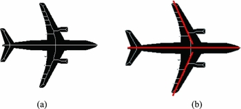
It is difficult to directly compare the extracted skeletons for two main reasons: (1) The skeleton is unstable. This is because some branches of the skeleton will be unconnected with each other, there are some extra branches in the skeleton, and some branches are not as wide as one pixel as shown in Fig. 3(a). (2) The existing line-fitting methods such as LSM (Least Square Method) and its variations cannot fit skeleton branches precisely(Reference Marco5). Therefore, we use several straight lines to fit the branches of the skeleton as illustrated in Fig. 3(b). The lines have the forms as in Equation (1)
 $$\begin{equation}
{a_i}x + {b_i}y + {c_i} = 0,i \in \left\{ {1,2,\ldots,n} \right\}
\end{equation}$$
Illustration of the skeleton and fitting lines for a segmented aircraft. (a) The skeleton overlapped on the segmented aircraft image. (b) The obtained fitting lines marked in red.

where n represents the total number of the fitting straight lines. Taking shift invariance into account, parameter ci can be omitted and only parameter (ai , bi ) is used to describe the characteristic of each straight line. The set of the fitting straight lines can represent the aircraft's structure. Once obtaining the structure information of an aircraft, we can next extract the geometry structure features to estimate its pose as shown in Fig. 1(d).
3.0 POSE ESTIMATION
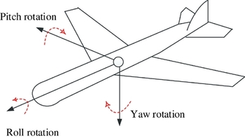
An aircraft in flight is free to rotate in three dimensions as illustrated in Fig. 4: pitch (nose up or down around an axis running from wing to wing), roll (rotation around an axis running from nose to tail) and yaw (nose left or right around an axis running up and down). When the optical axis of the camera is properly placed perpendicular to the runway as shown in Fig. 2, the yaw can be reduced. Therefore, the aircraft's pose can be effectively estimated by obtaining the pitch information and the roll information.
The three rotation directions of an aircraft in flight.

3.1 Features about pitch information
Since the pitch information can be represented by the angle between the aircraft's longitudinal axis and horizontal direction, the pitch orientation can be obtained through a line-fitting process to get the aircraft's longitudinal axis as seen the red line in Fig. 1(d).
The most common type of line fitting methods are the Least Square Method (LSM) and its favors, which take all the data into account to obtain the linear model. The main drawback of LSM is that it is easily influenced by bad points which are defined as outliers in Ref. [23]. The RANSAC algorithm is a good data processing method and was first introduced to solve the location determination problem. It can handle data that has more than 50% outliers in the dataset(Reference Marco5). Comparing with LSM that makes use of all the data available, RANSAC randomly samples a minimal data set (“minimal” means the fewest points to calculate model parameters) from observed data and then enlarges the set using consistent data that fits the calculated model. Then it employs an effective smoothing technique to compute an improved model when enough compatible points are obtained.
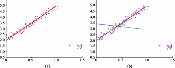
An intuitive example is shown in Fig. 5, where the artificial dataset represented by red points combining two groups of data as shown in Fig. 5(a). One group consists of 200 points generated by the model y = 3x + 2 (denoted as a red line) with normally distributed random noise n 1 ~ N(0, 0.05), and the other group includes 20 random points satisfying n 2 ~ N(1.5, 0.1). In Fig. 5(b), the blue line and green line are the results by LSM and RANSAC, respectively. The magenta points and blue points are the outliers and inliers of the RANSAC result. From Fig. 5(b), we see that RANSAC can accurately fit the objective model, but LSM is greatly influenced by the outliers and is subject to error, demonstrating the robustness of RANSAC in relation to outliers. When LSM and RANSAC are performed to fit the longitudinal axis of an aircraft, RANSAC can also obtain more accurate results, one example of which is shown in Fig. 6 where (a) is the segmented image of an aircraft, (b) is the extracted skeleton, and (c) illustrates the results by LSM and RANSAC. In Fig. 6(c), the red line is for LSM and the green line is for RANSAC. It is obvious that the RANSAC results are more precise for fitting the longitudinal axis of the aircraft.
Line-fitting results of artificial data by LSM and RANSAC where (a) is the artificial dataset and (b) shows the results by LSM (blue line) and RANSAC (green line).

The fitted longitudinal axis of the aircraft where (a) is the segmented image of an aircraft. (b) is the extracted skeleton, and (c) illustrates the results by LSM (red line) and RANSAC (green line).

The output of RANSAC is a straight line, which can be represented by Equation (2):
 $$\begin{equation}
y = ax + b,
\end{equation}$$
where a and b are the slope and the intercept of the fitting line (b can be ignored to keep the shift invariance). Then the pitch angle can be computed by Equation (3)
 $$\begin{equation}
\alpha = {\rm{Ta}}{{\rm{n}}^{ - 1}}a,
\end{equation}$$
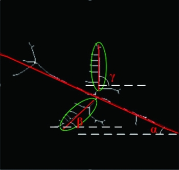
where α represents the pitch angle as illustrated in Fig. 7.
Features representing the aircraft's pose.

3.2 Features about roll information
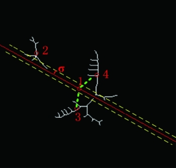
As shown in Fig. 7, the roll information of an aircraft is related to its aerofoil, namely β and γ, which are angles between the aerofoil branches of the skeleton and the horizontal direction. Therefore, β and γ can be represented by the aerofoil branches of the skeleton. For this purpose, a threshold σ is first used to remove the aircraft's longitudinal axis from the extracted skeleton structure Ω. As illustrated in Fig. 8, set (xi , yi ) = (0, 0) and ∀(xi , yi ) ∈ Ω if it satisfies
 $$\begin{equation}
\frac{{\left| {{y_i} - a{x_i} - b} \right|}}{{\sqrt {(1 + {a^2})} }} \le \sigma
\end{equation}$$
Removing the aircraft skeleton and finding its aerofoil branches.

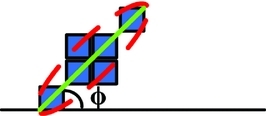
Then we compute the centroid of each connected branch for the rest skeleton structure one by one. The centroids of the two aerofoil branches (marked as 3 and 4 in Fig. 8) will correspond to the two nearest aerofoil branches of the centroid of the aircraft longitudinal axis (marked as 1 in Fig. 8). Since the aerofoil branches of the skeleton are irregular as shown in Fig. 8, it is difficult to directly fit a linear model to every aerofoil branch for estimating the angle parameters. Therefore, we use the major axis of an equivalent ellipse to extract the orientation of the aerofoils. The equivalent ellipse has the same normalised second central moment as the irregular shape(Reference Sun25). A very intuitive description of this method is shown in Fig. 9, in which the blue squares represent pixels of a shape and ϕ represents the orientation of the green line, which is the major axis of the equivalent ellipse.
The orientation information of a shape computed by an equivalent ellipse.

Without loss of generality, an ellipse centred at (x 0, y 0) can be defined as
 $$\begin{equation}
{\left(\begin{array}{l} x - {x_0}\\ y - {y_0} \end{array}\right)^T}{{\bf A}}\left(\begin{array}{l} x - {x_0}\\ y - {y_0} \end{array} \right) = 1,
\end{equation}$$
where A is a symmetric positive definite matrix. The ellipse matrix A can be computed by the normalised second central moments B (Reference Haralick and Shapiro24) as below:
 $$\begin{equation}
{{\bf A}} = \frac{1}{4}{{{\bf B}}^{ - 1}},
\end{equation}$$
where B can be represented as
 $$\begin{equation}
{{\bf B}} = \left({\begin{array}{*{20}{c}} \begin{array}{l} {\mu _{xx}}\\ {\mu _{xy}} \end{array}&\begin{array}{l} {\mu _{xy}}\\ {\mu _{yy}} \end{array} \end{array}} \right)
\end{equation}$$
According to the definition of central moments, the counter-clockwise orientation of the major axis relative to the vertical axis is given as
 $$\begin{equation}
\varphi = \left\{\begin{array}{l}\begin{array}{*{20}{c}} {{\rm{Ta}}{{\rm{n}}^{ - 1}}\left({\frac{{{\mu _{xx}} - {\mu _{yy}} + \sqrt {{{({\mu _{xx}} - {\mu _{yy}})}^2} + 4\mu _{xy}^2} }}{{ - 2{\mu _{xy}}}}} \right),}&{{\mu _{xx}} > {\mu _{yy}}} \end{array}\\[14pt]
\begin{array}{*{20}{c}} {{\rm{Ta}}{{\rm{n}}^{ - 1}}\left({\frac{{ - 2{\mu _{xy}}}}{{{\mu _{yy}} - {\mu _{xx}} + \sqrt {{{({\mu _{yy}} - {\mu _{xx}})}^2} + 4\mu _{xy}^2} }}} \right),}&{{\mu _{xx}} \le {\mu _{yy}}} \end{array} \end{array} \right.
\end{equation}$$
The elements in matrix B can be computed using irregular shape pixels I(x, y)(Reference Sun25,Reference Hu26)
 $$\begin{equation}
\left\{\begin{array}{l} {\mu _{xx}} = \displaystyle\frac{{\int\!\!\int {{{(x - \bar{x})}^{2}}I(x,y)dxdy}}}{{\int\!\!\int {I(x,y)dxdy}}}\\[16pt] {\mu _{yy}} = \displaystyle\frac{{\int\!\!\int {{{(y - \bar{y})}^2}I(x,y)dxdy}}}{{\int\!\!\int {I(x,y)dxdy}}}\\[16pt] {\mu _{xy}} = \displaystyle\frac{{\int\!\!\int {(x - \bar{x})(y - \bar{y})I(x,y)dxdy}}}{{\int\!\!\int {I(x,y)dxdy}}} \end{array}\right.,
\end{equation}$$
where
 $\bar{x}$
and
 $\bar{y}$
are centroids of the shape and have the following forms:
 $$\begin{equation}
\left\{\begin{array}{l} \bar x = \displaystyle\frac{{\int\!\!\int {xI(x,y)dxdy}}}{{\int\int {I(x,y)dxdy}}}\\[16pt] \bar y = \displaystyle\frac{{\int\!\!\int {yI(x,y)dxdy}}}{{\int\!\!\int {I(x,y)dxdy}}} \end{array}\right.
\end{equation}$$
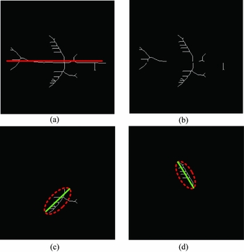
Substituting values from Equations (9) and (10) into (Reference Zuffi, Learndini, Catani, Fantozzi and Cappello8), we can obtain the orientation information of a shape computed by the equivalent ellipse. The whole process of extracting features about roll information is illustrated in Fig. 10. We first use the RANSAC algorithm to extract the features about pitch information as shown in Fig. 10(a), and Equation (4) is used to remove the aircraft longitudinal axis from the extracted skeleton structure as shown in Fig. 10(b). Then the orientations of two aerofoil branches are calculated with the central moment by Equation (8)-(10). Figure 10(c-d) illustrates the aerofoil features, from which it can be found that the central moment method can achieve a satisfying estimation of the aerofoil information.
The process of extracting features about roll information where (a) is the fitting result of RANSAC, (b) is remaining skeleton structure except the aircraft longitudinal axis by Equation (4), and (c) and (d) are the aerofoil orientations represented with green lines.

Since β and γ are angles between the major axis of aerofoil branches and the horizontal direction and φ in Equation (8) describes the major axis relative to the vertical axis, we can make a transformation as below
 $$\begin{equation}
\left\{\begin{array}{l} \beta = {\varphi _1} + {90^ \circ }\\ \gamma = {\varphi _2} + {90^ \circ } \end{array}\right.,
\end{equation}$$
where φ 1 and φ 2 are calculated by Equation (8), corresponding to β and γ, respectively.
4.0 TWO-STEP FEATURE MATCHING ALGORITHM
After getting features (α, β, γ), we finish the pose estimation of the aircraft. In order to test the accuracy of the proposed features, a two-step feature-matching algorithm is designed to compare the query image with the prototype database. The database includes pre-obtained aircraft images of different roll angles and pitch angles, and therefore we can get the estimated pose of an unknown query image by obtaining the index of the most similar prototype image with the query image.
As for implementation, since α and (β, γ) measure the aircraft's pose from two different aspects, we will measure the similarity between the query image and the prototype image by a two-step decision-tree-like method. The m most similar prototype images are first discovered from the prototype database S by parameter α, which can be written below:
 $$\begin{equation}
\left\{\begin{array}{l} \mathop {\max }\limits_{i \in {{{\bf S}}^{{\rm{pitch}}}}} \left({\frac{{{{\left\| {\alpha - {\alpha _i}} \right\|}_1}}}{{{{180}^ \circ }}}} \right) \le \mathop {\min }\limits_{j \in \left({{{\bf S}} - {{{\bf S}}^{{\rm{pitch}}}}} \right)} \left({\frac{{{{\left\| {\alpha - {\alpha _j}} \right\|}_1}}}{{{{180}^ \circ }}}} \right)\\[16pt] \left| {{{{\bf S}}^{{\rm{pitch}}}}} \right| = m \end{array}\right.,
\end{equation}$$
where α is the feature about pitch information of the query image, α i is the feature about pitch information of the ith prototype image, | · | computes the cardinality of the argument, ‖ · ‖1 computes the 1-norm distance of the arguments, n is the total number of prototype database, and 180° is divided to transform degree into radian. S pitch consists of m indexes corresponding to the m most similar prototype images with the query image. Here we suggest m is twice the number of the roll angles in the prototype database.
Then, the most similar prototype image can be further obtained according to (β, γ), which can be written as
 $$\begin{equation}
ID = \mathop {\arg \min }\limits_j \left({{{\left\| {\beta - {\beta _j}} \right\|}_1} + {{\left\| {\gamma - {\gamma _j}} \right\|}_1}} \right),j \in {{{\bf S}}^{{\rm{pitch}}}},
\end{equation}$$
where ID represents the index of matched prototype image of the query image, and (β, γ) is the extracted feature about roll information of the query image and (β j , γ j ) is that of the ith prototype image.
This two-step matching strategy can independently estimate the roll angle and pitch angle of an aircraft, and therefore avoid the interaction between the roll information and pitch information so as to maximise the discriminability of the similarity measure between features. The overall process of the proposed method is illustrated by Fig. 11.
Flowchart of the proposed algorithm.

5.0 EXPERIMENTS
5.1 Experiment setup
In this section, we design experiments to validate the effectiveness of the proposed features and algorithm. Since different aircrafts have different aerofoil structures that will lead to different skeleton results, two models are created to simulate the two common commercial aircrafts, the Boeing series and the Airbus series as shown in Fig. 12. The prototype images in Fig. 13 is acquired by rotating these two models around x and y axis respectively to imitate the changes of the roll angle θ and pitch angle φ. The sampled θ and φ are shown in Table 1, where a total number of 66 prototype images are acquired for each model. Our query images are obtained in the same way with different θ and φ shown in Table 1. It can be seen that there are differences between the query images and the prototype images which can validate the robustness of the proposed method. The total number of our query images for each model is 60. Both the prototype images and query images have the same size of 270×269 for Model 1 and 238×247 for Model 2.
Two aircraft models: (a) Model 1 and (b) Model 2Footnote 2 .

Images database gained by rotating θ and φ.

The roll angle θ and pitch angle ϕ of the simulated prototype and query images.

The parameters of the proposed method are set as follows. Since the extracted skeleton is one pixel wide and there is no need to delete too many skeleton points while removing the aircraft longitudinal axis, the threshold σ = 2. The parameters in RANSAC are set according to Ref. [23]: (Reference Van Es1) the error tolerance ɛ, which determines whether a point can be accepted by a model or not. Let ε = 0.3, which means a point belongs to the random selected model if the distance between this point and the model is less than 0.3. (Reference Pavlin and Bračić2) w = 0.05, which is the ratio of inlier size to total data size. (Reference Dumont, Berthiaume, Laurent, Debaque and Prévost3) The maximum trail threshold k is the maximum trail to select new subsets from data and is equal to 2000 in this paper. (Reference Bai, Latecki and Liu4) The probability p = 0.99 is related to the selection of the inliers from the input data set in some iteration. (Reference Marco5) Since RANSAC will fit a straight line, the least number n of points to fit the model is set to 2.
5.2 Experiment results and analysis
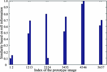
We first use one query image to validate the algorithm by illustrating the intermediate results step by step. The first image in the query images database of Mode l is chosen whose angle parameter is (θ, ϕ) = (− 60°, 45°). The features of the query image and the prototype images, which are (α, β, γ) = (44.1, −10.57, 64.36) and (α i , β i , γ i ), i = 1, 2, . . ., 66, are first extracted. Then the similarity based on pitch information between the query image and the prototype images is computed as shown in Fig. 14. According to the similarity, the m = 12 most similar prototype images S pitch are found according to Equation 12. Then the most matched prototype image can be further obtained by Equation 13. Figure 15 shows the similarity based on roll information, from which we can see that the prototype image of the index 1 is the most similar to the query image, which has the pose parameters (θ, ϕ) = (− 70°, 50°). This is the expected result, which indicates the effectiveness of the proposed method.
Comparison between α with α i , i = 1, 2, . . ., 66 using Euclidean distance.

Calculation of the Euclidean distance between (β, γ) and (β i , γ i ),j = 1, 2, . . ., m.

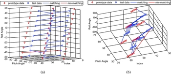
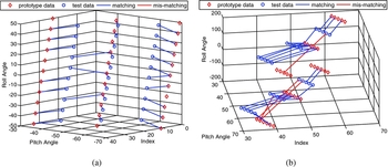
We next test all the query images following the same way above. Figures 16 and 17 show the matching results for Model 1 and 2 respectively, where the red diamonds represent prototype images and the blue circles are the query images. The lines connecting the red diamonds and the blue circles indicate the query image is matched with the prototype image. Since each query image has four neighbour prototype images, it will be considered correctively matched if the query image matches any one of the four images using Equations 12 and 13. Here, blue lines indicate correct matching and red lines represent mismatching. It can be seen that most of the lines are blue, which indicates the proposed algorithm can correctly match most of the query images with the corresponding prototype images. The matching accuracy is 96.67% for Model 1 and 93.33% for Model 2, which proves the effectiveness and accuracy of the proposed method. However, we also notice some red lines between the 9th image (whose angle parameter is (θ, ϕ) = (− 35°, −60°)) and 32th image ((− 40°, −30°)), the 32th image ((− 145°, 60°)) and 57th image ((− 140°, 30°)) for Model 1, the 42th image ((− 145°, 50°)) and 35th image ((− 140°, 70°)), the 51th image ((− 135°, 40°)) and 34th image ((− 130°, 70°)), the 52th image ((− 145°, 40°)) and 35th image ((− 140°, 70°)), the 59th image ((− 145°, 40°)) and 42th image ((− 150°, 70°)) for Model 2. Comparing two models and the images in the database, the angle between the aerofoil and the aircraft longitudinal axis in Model 1 is larger than that in Model 2. When the aerofoils and the aircraft longitudinal axis are simultaneously perpendicular to the camera's optical axis such as in the 32th image in Fig. 13, the axis from one aerofoil to the other aerofoil will influence the extraction of the aircraft longitudinal axis. In Model 2, since the angle between the aerofoil and the aircraft longitudinal axis is small, it is very easy for the aerofoils to be occluded by the aircraft's body such as in the 35th and 42th images in Fig. 13. Therefore, extracting features about roll information will be difficult for Model 2.
Illustration of the matching results of two databases for Model 1.

Illustration of the matching results of two databases for Model 2.

6.0 CONCLUSION
This paper proposes a geometry structure-based method to evaluate the pose parameters of an aircraft in runway end safety area from its 2D image. This method can be used to monitor the landing or takeoff of aircrafts and to predict the related aviation accidents and avoid loss of human lives and heavy material damage. A geometry structure feature is designed to describe the pose of an aircraft, which combines the RANSAC algorithm and the information of central moments. The former algorithm is used extract the aircraft longitudinal axis, while the latter is adopted to represent the aerofoils. This kind of feature realises a novel idea to characterise the structure of the objects with rigid parts. In order to validate the proposed feature, we design a two-step feature-matching strategy to measure the feature similarity between the test database and the prototype database, which can avoid interactions between different kinds of information so as to maximise the discriminability of the similarity measure between features. Experiments on two common types of aircraft in Asia indicate that the proposed features can effectively estimate the pitch angle and the roll angle of an aircraft, and the algorithm can obtain results with a high degree of accuracy.
ACKNOWLEDGEMENTS
The authors would like to thank for the reviewers’ useful comments and suggestions on our manuscript. Hang Yu is the correspond author and helps a lot at all stages of refereeing, production and post-production stages. This work was supported by the National Natural Science Foundation of China under Grant Nos. 61203202, 61473228 and 61501352, China Postdoctoral Science Foundation under Grant No. 2014M562376, Natural Science Basic Research Plan in Shaanxi Province of China under Grant No. S2015YFJQ0573, and Fundamental Research Funds for the Central Universities under Grant Nos. JB141304 and JB151308.