INTRODUCTION
There is a permanent effort of laser facility builders to improve the beam properties of their systems, either beam optical qualities (mode structure, space and time shape, contrast, etc.) or energy and output power. The history of huge laser facilities shows that the upgrades have been done first by adding size-scaled amplifiers and later by pursuing new laser techniques, such as chirped pulse amplification (CPA) (Strickland & Mourou, Reference Strickland and Mourou1985) or optical parametric chirped pulse amplification (OPCPA) (Ross et al., Reference Ross, Matousek, Towrie, Langley, Collier, Danson, Hernandez-Gomez, Neely and Osvay1999). The first approach has been applied to solid-state lasers as well as gas lasers. Concerning gas lasers this approach has been used at MPQ Garching/Germany, where a several step upgrade of the iodine photo-dissociation laser Asterix was then completed in 1995 (Baumhacker et al., Reference Baumhacker, Brederlow, Fill, Volk, Witkowski and Witte1995) leading to a 3 TW output power at a duration of 0.4 ns. Usage of home-made pulse propagation code helped to improve the overall system extraction efficiency and optimize scaling to higher powers. It was given in Baumhacker et al. (Reference Baumhacker, Brederlow, Fill, Volk, Witkowski and Witte1995) that the flash lamp-pumped iodine laser Asterix IV has a potential for scaling up to 10 kJ, however, no such effort has been exerted in practice. The Asterix IV laser was moved to Prague/Czech Republic and since the year 2000 has been operated as a user facility under the name of Prague Asterix Laser System (PALS) (Rus et al., Reference Rus, Rohlena, Skála, Králiková, Jungwirth, Ullschmied, Witte and Baumhacker1999). Jungwirth (Reference Jungwirth2005) summarized the main research achievements at this laboratory. In ARSRIEP, Sarov/Russia the ISKRA iodine laser facility has been gradually built-up by adding amplifiers and optimizing the laser performance with the help of numerical simulations. ISKRA-5, a 12-channel facility started its operation in 1989 (Kirillov et al., Reference Kirillov, Murugov, Punin and Shemyakin1990) and is still in operation. The overall output is 30 kJ in 0.25 ns lasting pulses (Garanin, Reference Garanin2011). There is an exclusivity of the iodine systems, the spectral bandwidth is extremely narrow, only about 20 pm around 1315.24 nm. No CPA technique, therefore, could be used for an output power upgrade.
The new laser techniques CPA/OPCPA were successfully applied to solid-state lasers, e.g., to the United Kingdom key laser facility VULCAN at CLF of RAL in Oxfordshire, where a 100 TW CPA beam-line has been in operation since the end of the 20th century before being upgraded to a petawatt level in 2002 (Danson et al., Reference Danson, Brummitt, Clarke, Collier, Fell, Frackiewicz, Hancock, Hawkes, Hernandez-Gomez, Holligan, Hutchinson, Kidd, Lester, Musgrave, Neely, Neville, Norreys, Pepler, Reason, Shaikh, Winstone, Wyatt and Wyborn2004). The upgrade relied on a novel front-end based on the OPCPA technique, implementation of adaptive optics for beam quality improvement, adding one more disc amplifier etc. In Japan, at ILE in Osaka, GEKKO XII has been commissioned in 1983, 12 laser channels deliver about 10 kJ in frequency doubled beams at duration of 1 ns (Yamanaka et al., Reference Yamanaka, Kato, Izawa, Yoshida, Yamanaka, Sasaki, Nakatsuka, Mochizuki, Kuroda and Nakai1981). In 1996–1997, GEKKO XII was upgraded by addition of a 100 TW petawatt module CPA single beam laser (Kitagawa et al., Reference Kitagawa, Sentoku, Akamatsu, Mori, Tohyama, Kodama, Tanaka, Fujita, Yoshida, Matsuo, Jitsuno, Kawasaki, Sakabe, Nishimura, Izawa, Mima and Yamanaka2002). Later, upgrading the front end (OPCPA modules included) and other laser parts of the CPA beam, 1 PW was extracted and synchronized to GEKKO XII. The development proceeded further and the LFEX CPA system (10 kJ in 0.5–20 ps, four segmented beams) (Miyanaga et al., Reference Miyanaga, Azechi, Tanaka, Kanabe, Kanabe, Jitsuno, Kawanaka, Fujimoto, Kodama, Shiraga, Knodo, Tsubakimoto, Habara, Lu, Xu, Morio, Matsuo, Miyaji, Kawakami, Izawa and Mima2006) was commissioned in 2009. The NIF facility at the Lawrence Livermore National Laboratory, (Livermore, California), with its 192 beam-lines succeeded in emitting 500 TW peak-power shot of 1.85 MJ energy in July 2012 (Bishop, Reference Bishop2012). A new challenging project called advanced radiography capability (ARC) is under construction for upgrading the diagnostics arsenal. The CPA technique is used to convert four NIF beams into eight petawatt-class beams based on new 1-10 ps fiber front-ends (Barty et al., Reference Barty, Key, Britten, Beach, Beer, Brown, Bryan, Caird, Carlson, Crane, Dawson, Erlandson, Fittinghoff, Hermann, Hoaglan, Iyer, Jones II, Jovanovic, Komashko, Landen, Liao, Molander, Mitchell, Moses, Nielsen, Nguyen, Nissen, Payne, Pennington, Risinger, Rushford, Skulina, Spaeth, Stuart, Tietbohl and Wattellier2004).
The up-to-now performed output power upgrades of ultra-high power laser facilities approve that new front-ends based on the OPCPA technique present a real benefit. First of all the pulse contrast was improved due to a short period of energy transfer between the pump and the signal, then very high gain over a broad spectral range was attained, and, moreover, signal gain narrowing can be compensated via appropriate amplifier tuning or temporal pump beam shaping.
The OPCPA technique, however, has a great potential if applied also in final laser stages, for similar reasons as in the front-ends. It was successfully explored at CLF RAL (Chekhlov et al., Reference Chekhlov, Collier, Ross, Bates, Notley, Hernandez-Gomez, Shaikh, Danson, Neely, Matousek and Hancock2006), where the present 10 PW VULCAN upgrade has been under construction, and further at IAP RAS, Nizhny Novgorod (Lozhkarev et al., Reference Lozhkarev, Freidman, Ginzburg, Katin, Khazanov, Kirsanov, Luchinin, Mal'shakov, Martyanov, Palashov, Poteomkin, Sergeev, Shaykin and Yakovlev2007).
The OPCPA upgrades do not restrict to solid-state lasers only but are beneficial also for narrow-band gas lasers, which we have proved experimentally. A single shot high-power iodine laser SOFIA (Dostal et al., Reference Dostal, Turcicova, Kralikova, Kral and Huynh2009) was used to pump parametric amplifiers, based on LBO and KDP crystals, amplifying pulses of a Ti:sapphire laser oscillator at 800 nm central wavelength. The overall energy gain of over 108 was achieved in a pulse of 27 fs duration and 1 TW level output power (Novák et al., Reference Novák, Turcicova, Divoky, Smrz, Huynh and Straka2012a; Reference Novák, Turčičová, Divoký, Smrž, Huynh and Straka2012b; Reference Novák, Turcicova, Smrz, Huynh, Pfeifer and Straka2012c).
In our paper, a design and possible layout of a petawatt upgrade of PALS is presented. This single beam laser is unique by its working wavelength 1315 nm and one of the highest energy in Europe. Asterix IV, with its single kilojoule level beam and a high spatial uniformity, was proclaimed an ideal driver for the petawatt OPCPA (Matousek et al., Reference Matousek, Rus and Ross2000). The implementation procedure of the petawatt upgrade was outlined in (Straka et al., Reference Straka, Turcicova, Rohlena, Rus, Skala, Kralikova, Ullschmied and Jungwirth2002). However, rather idealized conditions of the iodine beam passage through the entire optical system were assumed. Our current proposal takes into account real safe conditions in the daily performance of the PALS system, meaning the energy of 0.7 kJ in the main beam compared to 1 kJ used previously. The paper presents a new option for the PALS Research Centre, i.e., two ultra-high power beam-lines. One is designed for the generation of a 130 TW beam, which if necessary, can be combined with the high-energy long pulse of the iodine laser. The other envisages 1.4 PW of output power. A possible layout of the new systems in the left-over space in the contemporary laser hall is included.
DESIGN OF 130 TW AND 1.4 PW BEAMS
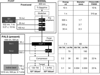
An energy scheme of the 130 TW and 1.4 PW beams has been elaborated and supported by calculations of the coupled wave equations (Ross et al., Reference Ross, Matousek, New and Osvay2002). The component layout including specifications of the energy, beam diameter, and pulse duration throughout the proposed laser system is presented in Figure 1.
Schematic of the present iodine laser PALS (light gray) and proposed 130 TW (dashed) and 1.4 PW (solid) signal beams (black). Pump beams (dark gray) are the second harmonic (SH) of the Nd:YAG laser in the front-end and third harmonic (TH) of the iodine laser for the power amplifiers. The new 130 TW beam is available for target experiments together with the present 0.7 kJ iodine laser main beam (dashed light gray). The table on the right presents the output parameters of the signal beams in relevant points of the amplification chain.

Signal and Pump Beams
The signal beam is formed by femtosecond pulses of 10 nJ energy, 10 fs duration, and about 100 nm spectral bandwidth around the central 800 nm wavelength, generated by a Ti:sapphire laser. The double-pass stretcher based on an Offner telescope and a single ruled gold coated grating of 1200 grooves/mm density utilizing in-plane diffraction lengthens the pulse duration to 310 ps, the value proposed in numerical solutions (Matousek et al., Reference Matousek, Rus and Ross2000) for the output maximization of the power amplifiers for a 500 ps pump pulse width. The initial pump and signal pulse temporal profiles are supposed to be Gaussian and their maxima are synchronized.
The pump beam intensities at the maxima correspond approximately to a half of the damage threshold of the prospective crystals, i.e., 3 GW/cm2 in LBO, 2 GW/cm2 in KDP, and 0.5 GW/cm2 in BBO.
The beam diameters are adjusted by lens telescopes, some of them used as spatial filters. At the same time the telescopes image-relay the beams between the successive parametric amplifiers. The telescopes handling the spectrally broadband signal beam are equipped with achromatic lenses and those for imaging highly intense beams, either pump or amplified signal, are evacuated. The spherical aberration is minimized using lenses of f/# ≥20. Both the signal and pump beams are taken as circular and of the same diameter in each power amplifier.
Minimum aperture of optical elements is determined by the beam diameter that encircles 99% of the beam energy, e.g., in the power amplifier the aperture is at least 1.2 larger than a full width at half maximum (FWHM) diameter of the relevant top-hat-like beams. The beam energy transmission between the amplifiers is assumed to be about 80% and involves transmission losses of optical elements including the spatial filters and beam diagnostics.
Pulse Synchronization
One of a few disadvantages of the OPCPA technique is the requirement for a precise synchronization of the beams. This requirement is even more demanding for the iodine laser as the optical synchronization directly by a split optical beam is not possible due to the very narrow bandwidth of the iodine amplifiers of about 20 pm. Two options of the synchronization of the signal and pump beams have been tested.
In the first one, an actively triggered solid-state oscillator was used instead of the iodine gas front-end and synchronized with the pulses from the signal, passively mode-locked, Ti:sapphire laser. This scenario has been tested in the SOFIA laboratory (Dostal et al., Reference Dostal, Turcicova, Kralikova, Kral and Huynh2009). An optical parametric oscillator (OPO) pumped by an actively Q-switched (synchronized with the Ti:sapphire laser) Nd:YAG laser was the source of oscillator pulses feeding the iodine amplifiers. Before reaching the amplifiers the pulses were cut by two Pockels cells activated also by a synchronizing pulse from the Ti:sapphire laser. Using the idler wave of the OPO as the oscillator beam provided enough energy on milijoule level, however, brought about a worse mode structure of the beam and energy fluctuations in pulses. This option introduced 100 ps jitter into the synchronization of the signal and pump beams in the OPA amplifiers.
In the other method, both oscillators of the pump and signal lasers are controlled by a 38.12 MHz radio-frequency master clock. The iodine oscillator of the PALS laser uses a master-clock-controlled acousto-optic modulator for the active mode locking. The double frequency of the master-clock controls also a synchro-lock unit adjusting the resonator length of a signal Ti:sapphire laser so that its resonator round-trip time corresponds to that of the iodine oscillator (Dostal et al., Reference Dostal, Dudzak, Huynh, Pfeifer, Skala, Ullschmied and Jesatko2012). Pulses from both the laser devices are thus synchronized to the MHz source with the synchronization jitter between the pulses of ±100 ps.
To complete the problem of the synchronization, an attempt to seed the iodine oscillator by an externally triggerable fiber oscillator must be mentioned. The fiber oscillator consisted of a DFB laser diode thermally stabilized at the iodine line of 1315 nm followed by a semiconductor and a two-stage Pr3+-doped fiber amplifiers (Jedlička et al., Reference Jedlička, Lazar and Číp2006). The problem with the fiber oscillator is that in spite of a filter, 1 nm at FWHM, its output is spectrally broad for the iodine amplifier seeding and with a low contrast. The benefit of the fiber-oscillator seed has not been fully unlocked.
Parametric Amplifiers
To broaden the spectral gain bandwidth and enable the separation of the beams after the amplification, a non-collinear geometry of the beams in the parametric amplifiers is used (ooe phase matching). The amplification in the parametric preamplifiers is supposed to be up to 1000 per stage and a repetition rate of 1 Hz at least, for simplification of the alignment procedure. A high conversion efficiency of about 20% is assumed in our power amplifiers, corresponding to the calculations and experimental values given in (Lozhkarev et al., Reference Lozhkarev, Freidman, Ginzburg, Katin, Khazanov, Kirsanov, Luchinin, Mal'shakov, Martyanov, Palashov, Poteomkin, Sergeev, Shaykin and Yakovlev2007).
FRONT-END
We designed a new front-end consisting of three crystal preamplifiers pumped by a frequency doubled beam (532 nm) of a commercial Q-switched Nd:YAG laser running at 10 Hz. It enables quick adjustment and optimization of the preamplifiers. Moreover, amplification realized in a couple of low-gain preamplifiers is more favorable for a better contrast of pulses (Tavella et al., Reference Tavella, Marcinkevicius and Krausz2006). Concerning the choice of the front-end crystals, the BBO crystals are preferred to LBOs as they support by 5% broader spectrum at 532 nm pumping. Further, the LBO crystal needs higher pumping intensity, which increases loading of other optical elements. The KDP and DKDP crystals are not convenient for the pre-amplification as they do not support such a broadband amplification around 800 nm if pumped by the second harmonic of the Nd:YAG laser.
The signal pulses are successively parametrically amplified from 1 nJ to an energy of 30 mJ in the front-end comprising three BBO crystals of 12 mm length. The internal angle of phase matching is determined to 23.7° and that of non-collinearity 2.2°, supporting the amplification of 90 nm broad spectrum. The pump wave-vector is closer to the crystal optical axis than the signal wave-vector in order to increase the interaction length by compensating for the spatial walk-off between the signal and pump Poynting vectors. However, for a higher spectral stability of the amplified signal, the other beam geometry may be advantageous. The pumping of the BBO crystals peaks at 0.5 GW/cm2 intensity in each crystal. The signal amplification is about 500 in the first two preamplifiers and 180 in the third one. The conversion efficiency increases from several 0.001% in the first preamplifier up to 20% in the third one operated in saturation. The generation of parametric fluorescence is limited additionally by fast Pockels cells, which cut the pump pulse duration to about 1 ns, the value comparable in order with that of the signal pulse. The pumping data given in Figure 1 correspond to the cut pulses.
POWER AMPLIFIERS
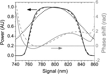
The KDP crystal is favored for the broadband power amplifiers which are pumped by the third harmonic of the iodine laser with the wavelength of 438 nm. Under such pumping, the BBO and LBO crystals would support a broader spectrum; however, the KDP crystal is commercially available in large apertures that are needed for ultra-high-power beams. The calculated internal angle of the phase matching is 43.4° and that of non-collinearity is 1.3°. The amplification in the first power amplifier is 330 and conversion efficiency 18%, which enables 130 TW power of the compressed pulse. The 32 mm long KDP crystal (KDP 1 in Fig. 1) is pumped by the third harmonic of an auxiliary PALS beam at an intensity of 2 GW/cm2. The auxiliary beam is produced by 40% splitting of the PALS beam prior the last iodine amplifier. The auxiliary beam is telescopically adjusted so as a 50% conversion efficiency of the third harmonic generation is achieved providing 30 J of the pump energy. The spectral bandwidth of the parametrically amplified signal beam after the KDP crystal is 74 nm FWHM, see Figure 2.
Input (dotted) and amplified spectra (black), and a spectral phase-shift (gray) of the 130 TW (dashed) and 1.4 PW beams (solid) caused by the parametric amplification.

The option leading to the petawatts is to further amplify the beam from the first KDP in a second, 20 mm long crystal (KDP 2 in Fig. 1); the amplification is 16 at 25% conversion efficiency. The crystal is pumped by the frequency tripled main PALS beam at an intensity of 2 GW/cm2. The bandwidth of the amplified spectrum is 77 nm FWHM (see Fig. 2).
The signal beam profiles follow top-hat PALS beam profiles in the power amplifiers. The calculated value of the B-integral in the preamplifiers is <0.1 and in the power amplifiers is <0.2 which guarantees that nonlinear phenomena, such as self-focusing, are weak and no substantial beam quality worsening due to its high intensity will appear. The beam diagnostics between the amplifiers covers the measurement of the pulse energy, temporal evolution and synchronization of the beams, spatial profiles in the near- and far-fields and spectra of the pulses. The diagnostics was in its principal version verified on the OPCPA system pumped by the iodine system of SOFIA (Novák et al., Reference Novák, Divoký, Bohm, Smrž, Sedlář, Straka and Turčičová2008).
COMPRESSION AND FOCUSING
The double-pass stretcher and compressor of the pulses use currently available metal coated diffraction gratings with a groove density of 1200 gr/mm at a fluency less than 200 mJ/cm2, i.e., below the damage threshold. The efficiency of both devices is 50% for a spectrum of 200 nm bandwidth at 1% level and was experimentally verified (Novák et al., Reference Novák, Turcicova, Divoky, Smrz, Huynh and Straka2012a). To compensate for higher orders of dispersion, enabling compression close to the transform limit and optimize the amplification, a spatial light modulator or acoustic-optical programmable filter will be introduced into the system.
If compressing the output from the preamplifiers to 16 fs, being slightly above the transform limit, its peak would be 0.8 TW, i.e., the magnitude corresponding in order to the half-nanosecond pulse of the PALS facility. This short low-energy pulse could be used, e.g., for the diagnostics of a target plasma generated by the kJ iodine laser (Fig. 3a).
Scheme of the new beams combinations for target experiments at PALS. (a) the compressed preamplified 800 nm signal beam (dash-and-dot black) together with the auxiliary and main iodine laser beams (solid gray) either on the fundamental wavelength (1315 nm) or its harmonics; (b) the 130 TW beam (dashed black) with the main iodine laser beam (dashed gray); (c) the petawatt beam (solid black).

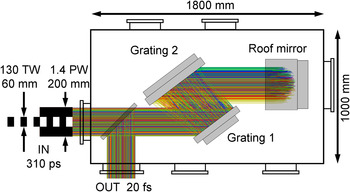
Both the ultra-high power beams share the same new designed two-grating in-plane compressor, aligned using two-dimensional-imaging spectrograph (Divoký & Straka, Reference Divoký and Straka2008). Ray tracing simulations of the signal beam in the compressor are shown in Figure 4. The size of the cylindrical compression chamber is 1000 mm in diameter and 1800 mm in length. The gratings are of 400 × 480 mm and 520 × 480 mm sizes. The angle of incidence on the gratings will be 53° and the energy fluency 150 mJ/cm2.
(Color online) Top view of the signal beam ray tracing through the newly designed grating compressor for both the 130 TW and 1.4 PW top-hat beams of 60 mm and 200 mm diameters, respectively, inside the compressor chamber (Novák et al., Reference Novák, Divoký, Bohm, Smrž, Sedlář, Straka and Turčičová2008).

The pulse from the first power amplifier can be temporally compressed to 22 fs (5% above the transform limit) giving peak power of 130 TW at an energy of 3.1 J. This beam can be utilized together with the main pulse of the PALS system, at the fundamental (energy of 0.7 kJ), second or third harmonic frequencies, for target experiments (Fig. 3b). The delay between the pulses can be adjusted in the range of ±10 ns by moving a delay mirror.
The PW beam diameter will be slightly enlarged to 200 mm prior the compressor entry as to keep the beam intensity below the damage threshold of the gratings. Fully amplified pulse compressed to 23 fs (5% above the transform limit) enables 1.4 PW output power at 34 J (Fig. 3c). Though the spectrum of 1.4 PW beam is slightly broader compared to 130 TW beam, the pulse duration is somewhat longer due to its shape and relatively narrower spectral wings.
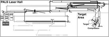
It follows from the above that the repetition rate of the new beams, 130 TW and 1.4 PW, is given by that of the pump PALS system, i.e., one shot per 25 min. Switching between ultra-high power beams, if necessary, is easily feasible by sliding three mirrors, see Figure 5, and changing the focusing and adaptive optics.
(Color online) Scheme of the present iodine PALS laser (light gray, hall dimensions 41 m × 15.5 m) and the new 130 TW and 1.4 PW signal beams (black) and their pump beams (dark gray). Filled rectangles – amplifiers, third harmonic generators (TH), telescopes (framed). Periscopes move the beams between the base level and top level up (P↑), or down (P↓). Slide mirrors (S) switch between the 130 TW (dashed) and PW (solid) beams.

A note should be made that already existing two-grating compressor of the SOFIA iodine beam (Novák et al., Reference Novák, Turcicova, Divoky, Smrz, Huynh and Straka2012a; Reference Novák, Turcicova, Smrz, Huynh, Pfeifer and Straka2012c), having 620 mm diameter and 1080 mm length, can also be used as a compressor for the 130 TW beam, if properly adapting the mounts of mirrors and gratings of 140 × 140 mm and 240 × 140 mm sizes for the 60 mm beam diameter. The compressor chamber can be opportunely utilized for the 130 TW beam if the ultra-high-power beams are implemented gradually.
A deformable mirror together with a wave-front sensor will be used for correcting the signal beam aberrations for both the 130 TW and 1.4 PW beams. This mirror of a medium diameter size 6 cm will be placed behind the first KDP crystal. Positioning of the deformable mirror in the middle of the amplifier chain is based on experimental verification by Canova et al. (Reference Canova, Flacco, Canova, Clady, Chambaret, Plé, Pittman, Planchon, Silva, Benocci, Lucchini, Batani, Lavergne, Dovillaire and Levecq2007). The wave-front sensor is planned to be behind the compressor. Focusing optics with an f/# of 2 is used for focusing the beam onto a target. The resulting beam will be focused by an off-axis parabolic mirror to a spot of 4 µm, assuming a two-times diffraction limited beam this entails target intensities of 1021–1022 W/cm2.
The interaction of the PW beam with the target will generate highly energetic radiation and particles. The interaction chamber and compressor will be radiation protected. For the γ radiation attenuation a 15 cm thick lead wall and 60 cm thick concrete block will be used. A 10 cm wall from the high density polyethylene will absorb the neutrons (Danson et al., Reference Danson, Brummitt, Clarke, Collier, Fell, Frackiewicz, Hawkes, Hernandez-Gomez, Holligan, Hutchinson, Kidd, Lester, Musgrave, Neely, Neville, Norreys, Pepler, Reason, Shaikh, Winstone, Wyatt and Wyborn2005).
LAY-OUT OF THE ULTRA-HIGH POWER BEAMS IN THE PALS LASER HALL
The building of the PALS Research Center can in no way be extended. Therefore any additional equipment has to fit into the present left-over space in the laser hall. A lay-out preparation of the new beams was governed by image-relaying requirements between the amplifiers, necessary corridors for the beams insertion into the crystals and their separation, synchronization of pulses in the amplifiers pumped by the auxiliary and main iodine beams, further by a synchronization of the 130 TW and main PALS beams with a possibility of a controlled delay adjustment. All these issues can only be satisfied if some of the optical path parts of the new beams are located on an auxiliary platform constructed above the spatial filters of the present PALS beam.
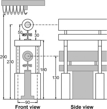
The image relaying requirement appeared as a serious constraint in the spatial layout design. A way out was the admission of possible tolerances ΔL between the images and positions of the parametric amplifiers in the image relays so that the energy conversion efficiency decrease would not exceed 10% compared to the maximum in the exact imaging. We found that for a beam diameter d given in mm the tolerance was ΔL = 10d 2. Spatial filtering was used for the beam “cleaning.” Non-collinear interaction of the beams and their subsequent separation are also space demanding, however, using dichroic mirrors for the beams separation substantially shortens the distances. The tolerance in the image relaying and usage of a dichroic mirror in the end OPA stage made it possible to accommodate the new ultra-high power beams tightly into the PALS laser hall. The optical axis of the present PALS beam is 130 cm above the floor (i.e., the base level) and the axis of power-amplifier parts of the new beams will be 230 cm above the floor (i.e. the top level), see Figures 5 and 6. The upper space is limited by a bridge crane. The new construction will be elevated only above the PALS spatial filters as the iodine amplifiers need regular maintenance and must be easily accessible.
(Color online) Scheme of the base level (gray) of the present PALS facility and the new top level (white) of the signal, with the beam profiles (hatch circle). The dimensions are in cm.

The proposed lay-out of the individual elements is in Figure 5. The Ti:sapphire laser, pulse stretcher, preamplifiers and Nd:YAG pumping laser are located on optical tables in the free space of the hall, the optical axis of the beams in preamplifiers is 110 cm above the floor. The main equipment for the power amplifiers is situated above the hardware of the actual laser system. Prior the compression the new ultra-high power beam is lowered to the level of the PALS main beam. The plane of the input beam is 24 cm lower than that of the output due to the reflection on the compressor roof mirror.
SUMMARY
It was shown that the OPCPA technique can be successfully implemented into the PALS Research Center, not only from the point of view of a possible substantial output power upgrade of the laser capabilities but also from the point of a practical realization. Quite new research activities of the users would be empowered as the present limit of radiation intensity on the target, 1016 W/cm2, would boost by 106 times. The upgrade design of the actual laser system is based on real every-day beam parameters. The robust equipment for the new 130 TW and 1.4 PW laser beams either fills the left-over space on the PALS laser hall ground floor or uses the free space above the spatial filters. No laser hall room extension is necessary. The 130 TW option enables a contemporaneous interaction experiment with the main kilojoule PALS beam and presents a middle step in the realization of the full-scale petawatt upgrade.
ACKNOWLEDGMENTS
Helpful supports from K. Jungwirth and J. Ullschmied are highly appreciated. The authors wish to thank the PALS team, namely J. Skála, E. Krouský and J. Kovář for expert assistance, and to P. Böhm for fruitful discussions on the optical compressor design. The work has been sponsored by the Ministry of Education, Youth and Sports of the Czech Republic (LN00A100 and LC528), the European Committee (6. FW, LASERLAB-EUROPE I and II, RII3-CT-2003-506350) and the Grant Agency of the Czech Republic (202/06/0814).