I. INTRODUCTION
The ability of ion beams to simulate neutron-induced damage effects and their main consequences on both microstructure and mechanical property changes in nuclear materials have been proposed in several studies. An article reviewing the use of ion beams to understand the effects of neutron irradiation was recently published. Reference Was and Averback1 The main advantages of this simulation process are linked to the versatility of the available experimental irradiation conditions (temperature, dose rate, fluence, and damaged thickness) and to the possibility to carry out in situ or ex situ physicochemical and structural characterization. Additional advantages are also expected: No (or very low) residual activation of the material, short irradiation times (hours versus months or years), and lower costs than reactor operation.
For that purpose, multiple ion beam facilities have been developed worldwide or are in the planning stage. Reference Hosemann2–Reference Was, Jiao, Getto, Sun, Monterrosa, Maloy, Anderoglu, Sencer and Hackett6 In France, a multi-ion beam irradiation platform called JANNUS (Joint Accelerators for Nanosciences and Nuclear Simulation) was established in 2005, jointly managed by three institutions: The “Commissariat à l’énergie atomique et aux énergies alternatives” (CEA), the “Centre National de la Recherche Scientifique” (CNRS), and the “Université Paris-Sud” (UPS). Reference Serruys, Trocellier, Miro, Bordas, Ruault, Kaïtasov, Henry, Leseigneur, Bonnaillie, Pellegrino, Vaubaillon and Uriot7 JANNUS is located on two neighboring sites at 25 km south of Paris. At Orsay, a 200 kV transmission electron microscope (TEM) is coupled with two ion accelerators (ARAMIS and IRMA) for in situ observation of the material microstructure modifications induced by ion irradiation/implantation. Reference Serruys, Trocellier, Miro, Bordas, Ruault, Kaïtasov, Henry, Leseigneur, Bonnaillie, Pellegrino, Vaubaillon and Uriot7 At CEA Saclay, the unique triple beam facility in Europe offers the simultaneous production of three ion beams for nuclear recoil damage and implantation of a large array of ions for well-controlled modeling-oriented experiments. Reference Pellegrino, Trocellier, Miro, Serruys, Bordas, Martin, Chaâbane, Vaubaillon, Gallien and Beck8 The first triple beam irradiation was performed in March 2010.
Along with irradiation developments, continuous efforts have been made to implement ex situ and in situ characterization tools.
As the JANNUS-Saclay is an open access facility providing beam time for national and international users, the main purpose of this paper is to present the status of the facility with recent equipment and examples of single-, dual-, and triple-beam irradiation configurations. We will focus on the instrumentation used for conducting multi-ion beam irradiations and implantations as well as for characterizing bombarded samples. On-line control of irradiation parameters, in situ modification monitoring using Raman spectroscopy or ion beam induced luminescence (IBIL), and ex situ characterization by ion beam surface analysis (Rutherford backscattering spectrometry (RBS), nuclear reaction analysis (NRA), and elastic recoil detection analysis (ERDA)) of implanted samples will be detailed.
II. MULTI-ION BEAM IRRADIATION
A. Ion sources and accelerators
1. Accelerators
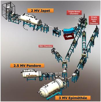
The JANNUS facility at Saclay is equipped with three electrostatic accelerators (respectively named Épiméthée, Japet, and Pandore) connected to a triple beam chamber for single-, dual-, and triple irradiations (Fig. 1). Two other chambers are linked to Épiméthée and Pandore for single beam irradiation and/or ion beam analysis (IBA). The layout is divided into six linked rooms, separated by suitable concrete walls for radioprotection safety. Three rooms contain one accelerator each, one more shielded room houses the magnets of two accelerators, and the two other rooms include the irradiation and IBA chambers.
Schematic top-view of the JANNUS-Saclay facility (walls are not represented).

Épiméthée is a 3 MV single-ended electrostatic accelerator [3-UH-2 Pelletron, National Electrostatics Corp. (NEC), Middleton, Wisconsin] equipped with an electron cyclotron resonance (ECR) source (Pantechnik, Nanogan type) able to provide highly damaging beams with large energies and ranges, and also beams for IBA. The ECR source produces high charge states of a variety of ion species, which in combination with the 3 MV acceleration potential can produce ion beams with energies as high as 36 MeV. The source is equipped with four bottles for gases such as O2, He, Ar, Xe, CH4 and two cartridges of volatile organometallic compounds (Metal Ions from Vapor of Organometallic Compounds (MIVOC)) such as ferrocene and W(CO)6 for Fe and W ion production. Maximal intensities at the targets are for example 9 × 10¹⁴ pps (particles per second) for protons and He+, 6 × 10¹³ pps for Fe+ to 1.4 × 10¹¹ pps for Fe11+, and 1 × 10¹³ pps for W7+ to 1.4 × 10¹² pps for W12+.
Japet is a 2 MV Tandem Pelletron (6SDH-2, NEC, Middleton, Wisconsin) equipped with an external SNICS II ion source (cesium sputter source). This system is capable to deliver energies of 0.5–4.0 MeV for singly charged ions, up to 6 MeV for doubly charged ions, and correspondingly higher energies for ions of higher charge states. This source can deliver electronegative ions such as Cl and I and also ions of C, Si, V, Cu, Zr, Ag, and Au. Maximal intensities are for example 3.2 × 10¹⁴ pps for protons, 4 × 10¹² pps for V+ to 2.2 × 10¹¹ pps for V5+, and 1.75 × 10¹² pps for Au3+ to 3.75 × 10¹¹ pps for Au6+.
Pandore is a 2.5 MV single-ended electrostatic accelerator (7.5SH-2 Pelletron, NEC, Middleton, Wisconsin) equipped with a RF ion source. This accelerator replaces a 50 years old 2.5 Van de Graaff decommissioned in 2014. Six gas bottles are installed in the tank. Protons, deuterons, 3He and 4He ions, Kr ions up to Kr3+, and Ar ions up to Ar4+ can be produced. This accelerator is used for implantation and irradiation as well as for IBA.
2. Ion production
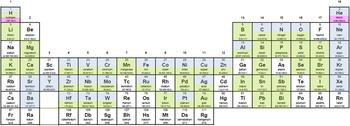
The three accelerators offer a broad choice of ion beams (Fig. 2) despite all the possibilities have not been explored. Four gases and two metals are permanently available on Épiméthée and six gases are permanently available on Pandore. On Japet, a single solid cathode is available at a time, but it can be changed rapidly.
In color, ions possibly produced by the accelerators of the JANNUS facility at Saclay (in blue by Épiméthée, in green by Japet, and in pink by Pandore). Among them, more than 20 ions have been successfully tested (see text).

Light ions—hydrogen, deuterium, and helium—can reach high intensities. Hydrogen is available on the three accelerators and helium on both Épiméthée and Pandore. 3He is available on Épiméthée and the excellent He2+ yield of its ECR source allows using both He isotopes up to 6 MeV. For radiation safety reasons, deuterium beams are only used with Pandore for IBA.
Heavier elements—carbon and oxygen—also give intense beams, both on Japet and Épiméthée. With the latter, C4+ is currently used and also O5+ for heavy ion elastic recoil analysis for example. Carbon is produced using methane, which also provides hydrogen ions. 13C from almost pure 13C graphite cathodes is used on Japet for tracer implantation. Nitrogen has never been tested, but would obviously be feasible on the three accelerators.
Rare gases can be produced by Épiméthée, but intensities strongly drop above charge states Ne4+, Ar9+, Kr9+, and Xe12+. Isotopic separation is not possible with xenon.
Metal ions are produced by the MIVOC process in the ECR source of Épiméthée. Fe8+ up to 24 MeV and W12+ up to 36 MeV are typically used to produce high damage levels up to the range of 3–4 µm. Permanent demand for iron and tungsten ions has limited the development of other metal ions to nickel, despite at least Ti, V, Cr, Co, Zr, and Y are feasible according to the literature. Japet provides excellent Cu, Au, and Al yields, and also abundant Si ions. Ni, Ti, and Zr ions are also quite satisfactory, but hardly above 14, 10, and 12 MeV, respectively. Weaker V, Ag, and Nb beams can also be produced by Japet.
The SNICS-II source of Japet is naturally very efficient for halogen ions: Chlorine and iodine. Bromine has not been tested yet, but there is no reason why it should show less efficient. Some minor but abundant enough natural isotopes such as 22Ne, 54Fe, and 57Fe have been used to produce very low intensities without jeopardizing the stability of the ECR source.
B. Irradiation chambers and on-line controls/measurements
1. Vacuum chambers for irradiation and IBA
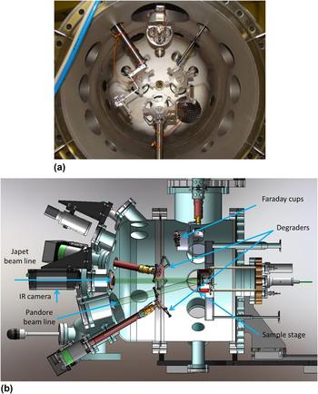
The triple beam chamber receives one beam line coming from each of the accelerators, allowing single, dual or triple beam irradiations (Fig. 3). Each one of the beam lines, converging toward the triple beam chamber with an incidence angle of 15°, is equipped with a raster scanner unit able to spread the beam homogeneously over an area of 2 cm in diameter on the sample surface.
The triple beam irradiation vacuum chamber. (a) Front-view of the chamber with back part open, showing the three nozzles of the three beams and the wheels for degraders. (b) Schematic representation of the chamber with two beams coming from Pandore and Japet (in light green) bombarding the sample.

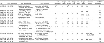
Each beam line can be equipped with an energy degrader to produce a roughly homogeneous irradiation damage and implantation(s) along the whole ion range [Fig. 3(a)]. The degraders are constituted by rotating wheels mounted with suitable thin foils, typically 25–250 µg cm−2 carbon foils or aluminum from 0.4 to 5 µm thick. Presentations of helium and damage profiles obtained with degraders can be found in Refs. Reference Prokhodtseva, Decamps and Schaeublin9–Reference Bhattacharya, Meslin, Henry, Pareige, Décamps, Genevois, Brimbal and Barbu11. For example, by using 24 MeV Fe8+ with Al-degrader foils, relatively homogeneous damage can be obtained from 1.5 to 3.2 µm depth in iron. In the triple beam configuration such as ref. 060614EYJ (Table I), degraders have been used for He and H ion beams to obtain even distribution of both implantations along with damage between 0.6 and 1 µm depth. Degraders induce ion loss due to divergence after scattering in the foils and straggling in the thickest foils. These phenomena are taken into account for the calculation of the implantation profiles. Reference Brimbal, Meslin, Henry, Décamps and Barbu10 Self-ion effect due to the superimposition of the damage region with implantation is taken into account by selecting an appropriate observation depth in the sample. Any extra ion effect resulting from a possible implantation of atom degraders is negligible.
Summary of the triple beam irradiations performed at JANNUS-Saclay. In addition to the CEA programs, these experiments were partially funded by: (*) EFDA (European Fusion Development Agreement), (**) EMIR (National Network of Accelerators dedicated to Material Irradiation), and (***) SPIRIT Transnational Access (Support of Public and Industrial Research using Ion beam Technology 2009–2013).

The sample holder mounted on the rear part of the chamber covers the temperature range from liquid nitrogen temperature to 800 °C [Fig. 3(b)]. On the top of the chamber, a pneumatic system holds three groups of seven Faraday cups designed to control the beam intensity.
A second vacuum chamber is linked to Épiméthée. It can be used for single beam irradiation or IBA. A Faraday mini-cups device and a heating/cooling stage sample holder are also available in this chamber, but not energy degrader. In this chamber, samples are irradiated at normal incidence. This layout allows connecting a user-designed chamber behind the single beam chamber and performing in situ diagnostics such as mechanical test or mass spectrometry analysis (see Sec. II. B. 4).
A third vacuum chamber is implemented on Pandore. It is an IBA chamber equipped with two x-ray detectors, a high purity germanium detector for gamma-ray detection, and two surface barrier detectors (100 and 1500 µm) usable for RBS, ERDA, and NRA measurements. This chamber is used for irradiated and nonirradiated sample characterization and also as a tool for controlling implanted doses (see Sec. IV). This beamline is also used for teaching purposes. Reference Beck, de Château-Thierry, Frontier, Trouslard and Pellegrino12
2. On-line current and dose measurement
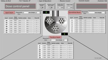
Current integration provides an accurate measurement of implanted species concentration. During irradiation, current is intermittently measured (30 s, every 10 or 20 min, typically) by a movable device of multi-Faraday cups. This approach is satisfactory with stable beams which is the case with the recent NEC accelerators. Beam profiler monitoring and dose postcontrols performed by IBA confirm the validity of this approach (see Sec. IV). In the triple beam chamber, the device is composed of three groups of seven Faraday mini-cups for spatial uniformity control of each beam (Fig. 4). Currents, number of incident particles, and accumulated doses are regularly monitored during irradiation and the beam intensities can be adjusted at any time to attain the requested dose for each ion in the same irradiation time.
View of the dose control panel showing the details of the multi-Faraday cup device and a display section for the values of currents, number of incident particles, accumulated doses, and remaining time for each beam.

3. Continuous temperature measurement
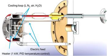
A heating–cooling sample stage has been developed for precise temperature control from liquid nitrogen temperature to 800 °C (Fig. 5). Low temperature irradiation/implantations (at −172 °C and from 1 to 20 °C) are managed by flowing LN in the sample stage. Higher temperature (from 20 to 800 °C) is obtained by heating the sample stage. One to five thermocouples are used to measure the sample temperature and another thermocouple (type K) is used for temperature regulation via proportional-integral-derivative (PID) control. A 2D infrared thermal imaging camera records the sample surface temperature during irradiation. Robust coupling of the samples to the sample holder and of the sample holder to the stage is important to achieve homogenous temperature. In most cases, sample holders are custom-built for each experiment.
Detail of the sample irradiation stage.

Another sample stage made of copper is used to cool samples down to liquid nitrogen temperature under higher beam intensities.
4. Additional irradiation chambers
Users of the facility can adapt appropriate chambers for specific applications. Three such user-designed chambers have been used up to now.
For mechanical applications, a tensile test device suitable for micrometrical samples, called MiniMécaSiC, has been developed to allow studies in various irradiation facilities. Reference Jankowiak, Grygiel, Monnet, Serruys, Colin, Miro, Gelebart, Gosmain and Costantini13 This device is designed to perform tensile tests on fibers up to 1000 °C. In situ strain behavior of 7–14 µm SiC fibers under ion beam irradiation has been investigated in real time under 6 MeV He and 12 MeV C ion beams. Reference Huguet-Garcia, Jankowiak, Miro, Serruys and Costantini14
For polymer studies, two chambers—CIGAL and CHIMERe—dedicated to the study of the chemical behavior of polymer foils under irradiation in a gas atmosphere have been installed at JANNUS by the users. Reference Dely, Ngono-Ravache, Ramillon and Balanzat15 For this purpose, irradiation is performed through a metallic (Havar®) window. Hydrogen and hydrocarbons release or oxygen incorporation are measured by mass spectrometry, in situ in the case of CIGAL. In CHIMERe, a push–pull movement of the sample continuously varies the thickness of the gas layer in front of the sample, which produces the effect of an energy degrader.
C. Irradiation modes
Single beam and simultaneous dual and triple beam irradiations can be performed at JANNUS-Saclay. As presented in Sec. II. A. 2, more than 20 ions have been tested and many combinations are available. However, the applications of the users mainly deal with nuclear materials, metals, and ceramics. As a result, most of the irradiations are conducted with iron, tungsten, gold, and helium ions.
For single beam irradiations (87% of total irradiations), Fe and W ions are used for the production of self-ion displacement damage in iron-based Reference Meslin, Radiguet and Loyer-Prost16 and tungsten-based materials. For ceramics, Au ions are chosen for their chemical neutral effect. Reference Pellegrino, Thomé, Debelle, Miro and Trocellier17,Reference Miro, Costantini, Sorieul, Gosmain and Thomé18 Damage rate up to 10 dpa/h can be obtained with these ions. 3He or 4He ions are implanted for studies focusing on gas diffusion mechanisms. Reference Trocellier, Miro, Serruys, Vaubaillon, Pellegrino, Agarwal, Moll and Beck19 More than 1017 He atoms/cm2 can be implanted in one day.
Dual beam irradiations (10% of total irradiations) are mainly devoted to explore synergistic effects of simultaneous ion displacement damage with helium injection, by combining Fe and 4He Reference Prokhodtseva, Decamps and Schaeublin9–Reference Bhattacharya, Meslin, Henry, Pareige, Décamps, Genevois, Brimbal and Barbu11,Reference Hsiung, Fluss, Tumey, Kuntz, El-Dasher, Wall, Choi, Kimura, Willaime and Serruys20,Reference Hsiung, Fluss, Tumey, Choi, Serruys, Willaime and Kimura21 or W and 4He. For example, self-ion irradiation (24 MeV Fe ions to 30 dpa) coupled with 1.7 MeV helium implantation (25 appm/dpa) was performed on Fe–Cr and Fe–Cr oxide dispersion strengthened (ODS) model alloys. Results of the dual-ion irradiation experiments have revealed the formation of a unimodal distribution of cavities in K3-ODS steel and a bimodal and uneven distribution of cavities in Fe–14Cr. Reference Hsiung, Fluss, Tumey, Choi, Serruys, Willaime and Kimura21 Heterogeneous nucleation of cavities has been observed in (2 MeV Fe + 2 MeV He) irradiated Fe–Cr model alloys. Reference Brimbal, Meslin, Henry, Décamps and Barbu10
Various other associations such as Si + C, Ti + C, W + I, W + Si, V + 3He, Au + Si, etc. have been also used. Simultaneous 900 keV I and 36 MeV W ion beams have been produced to study combined effects of nuclear (Sn) and electronic (Se) energy losses. Reference Thomé, Debelle, Garrido, Trocellier, Serruys, Velisa and Miro22 A strong decrease of the accumulated damage in comparison with single W ion irradiation has been observed in SiC and MgO showing a clear synergistic effect of nuclear and electronic energy losses in these materials. Reference Thomé, Velisa, Debelle, Miro, Garrido, Trocellier and Serruys23 This cooperative effect leads to a reduction of the damage production and could preserve the integrity of irradiated devices for nuclear application.
Triple beam irradiations almost exclusively resort to the Fe + 4He + H combinations to emulate fusion conditions and correspond to 3% of the total irradiations conducted at JANNUS-Saclay. Performed triple beam irradiations and related projects are reported in Table I. Most of the studies are still under investigation and very few papers have been so far published. Reference Brimbal, Miro, de Castro, Poissonnet, Trocellier, Serruys and Beck24,Reference de Castro, Briceno, Lozano-Perez, Trocellier, Roberts and Pareja25 These two papers are dealing with the first triple beam irradiation conducted on ODS steel (Fe–12wt% Cr–0.4wt% Y2O3) with Fe8+, He+, and H+ ions (ref. 110910ETJ). Although nanovoids and small gas-bubbles were not detected by TEM in the ODS steel with conclusive proof, since they are also present in the nonirradiated alloy, Raman spectrometry measurements have clearly identified the presence of the H2 molecule at the depth corresponding to the H+ implantation profile. Reference Brimbal, Miro, de Castro, Poissonnet, Trocellier, Serruys and Beck24 Conversely, H2 molecules have not been observed for H+ single beam irradiation in the same material demonstrating that the formation of the molecule H2 is linked to damage or He-associated cavities/bubbles. Reference Ogur, Yamaji, Higuchi, Imai, Itoh, Imanishi and Nakata26–Reference Takagi, Matsuoka, Tanaka, Akiyoshi and Sasaki28
III. IN SITU DAMAGE CHARACTERIZATION
Other irradiation facilities have developed in situ characterization techniques such as transmission electron microscopy (TEM), IBA, UV–vis, Raman, and x-ray diffraction (XRD). Reference Lescoat, Ribis, Gentils, Kaïtasov, de Carlan and Legris29–Reference Gibert-Mougel, Couvreur, Costantini, Bouffard, Levesque, Hémon, Paumier and Dufour34 At JANNUS-Saclay, a Raman probe is now permanently installed in the triple beam chamber and IBIL has been tested. Both devices are described in this section. In situ IBA will be implemented in the future.
A. Raman spectroscopy
Raman spectroscopy is an efficient technique for studying the evolution of the microstructure of materials under irradiation. For that purpose, a confocal Raman spectrometer has been installed at JANNUS-Saclay in 2013, which allows characterizing a variety of materials of nuclear interest. In March 2014, this spectrometer has been coupled to the triple beam chamber. The main objective of in situ Raman spectrometry is to monitor in real time the evolution of the damage induced by single-, dual-, or triple-beam irradiations.
The Raman spectrometer is a Renishaw Invia Reflex device equipped with a Leica DM2500 microscope (Wetzlar, Germany) with five objectives (x5, x20, x50, x50L, and x100). A 100 mW, frequency-doubled Nd:YAG (532 nm) laser, with four power filters to obtain 16 power levels (from 0.00005 to 100%), is used as the excitation source. This spectrometer includes two diffraction gratings (1800 and 2400 lines/mm) and edge filters. This facility aims at performing point acquisition but also 2D maps and depth scans.
Raman spectroscopy allows us to determine the phases present before and formed after irradiation, to outline the stress induced by irradiation, to evidence phase transition under irradiation, and to monitor the damage build-up. Damage has been investigated at different irradiation doses and temperatures and by varying the nuclear to electronic energy loss ratio. Reference Miro, Velisa, Thomé, Trocellier, Serruys, Debelle and Garrido35 Recrystallization phenomena have been studied after thermal annealing. Reference Miro, Costantini, Sorieul, Gosmain and Thomé18,Reference Miro, Costantini, Huguet-Garcia and Thomé36 Recently, ex situ Raman spectroscopy has evidenced the presence of molecular dihydrogen in an ODS steel (Fe–12wt% Cr–0.4wt% Y2O3) after a triple beam irradiation conducted with Fe8+, He+, and H+ ions. Reference Brimbal, Miro, de Castro, Poissonnet, Trocellier, Serruys and Beck24
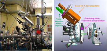
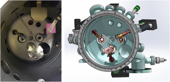
For in situ measurements, a dedicated device has been connected to the Raman spectrometer and to the triple beam chamber (Fig. 6).
Photo and drawing of the in situ Raman system connected to the triple beam chamber.

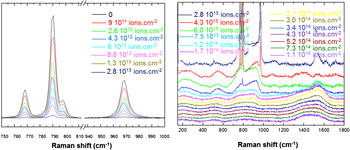
The first experiment performed with the in situ Raman system in the triple beam chamber concerns the evolution of the damage in silicon carbide (SiC) under irradiation with 4 MeV Au ions (Fig. 7). During irradiation, we observe a significant modification of the local structure: The increase in dose induces a progressive decreasing and broadening of the crystal phonon peaks. The crystal phonon peaks disappear at 1.2 × 10¹⁴ ions cm−2 and completely collapse at 3.0 × 10¹⁴ ions cm−2. Above this dose, the signal remains almost unchanged up to 1.1 × 10¹⁵ ions cm−2. This experiment has been conducted to the complete amorphization of the material in less than 3 h. For the same irradiation fluences, the spectra obtained are in very close agreement with those obtained under ex situ conditions on similar samples. Reference Miro, Costantini, Huguet-Garcia and Thomé36 The main advantages of the in situ Raman system lie in the following points: Time saving, avoiding annealing of defects, analysis of a same area, and kinetics experiments without interruption of the irradiation beam.
In situ Raman spectra of SiC irradiated with 4 MeV Au ions. Bands at 767, 789, 797, and 967 cm−1 assigned to 6H-SiC phonon mode decrease with ion fluence and disappear after 1.2 × 10¹⁴ Au ions/cm2 up to complete amorphization of SiC.

B. IBIL
In 2013, in collaboration with CMAM (Center for Micro-Analysis of Materials, Madrid), an IBIL or IL system was installed in the triple beam chamber for studying fusion materials during ion beam irradiation.
IBIL is a very sensitive technique for the analysis of impurities and defect centers introduced by irradiation. Therefore, in situ ionoluminescence during ion beam irradiations can be used to investigate the microscopic processes accompanying the generation of damage, the formation of color centers, and their kinetic evolution with the irradiation fluence. Reference Nagata, Yamamoto, Inouye, Tsuchiya, Toh and Shikama37,Reference Peňa-Rodríguez, Jimenéz-Rey, Manzano-Santamaría, Olivares, Muňoz, Rivera and Agulló-López38 The IBIL system, already used at CMAM, was implemented in the triple beam chamber (Fig. 8). The light emission was collected and transmitted through a silica optical fiber of 1 mm diameter. The light was guided to a compact spectrometer QE6500 (Ocean Optics Inc., Dunedin, FL) configured with a multichannel array detector for measuring simultaneously the whole spectrum in the 200–1000 nm range with a spectral resolution better than 2 nm.
Internal view and drawing of the triple beam chamber with the optical fiber placed in the median plane of the three beams.

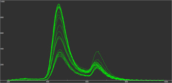
Figure 9 shows the IL emission spectra induced on amorphous silica (a-SiO2) during double beam irradiation by He and Ti ions. The spectra show two main emission bands attributed to the emission from the self-trapped excitons recombination at oxygen deficient centers (ODCs, blue band, 460 nm) and nonbridging oxygen hole centers (NBOHCs, red band, 650 nm). Each spectrum, recorded for 1 s, is collected for different times of irradiation. The peaks increase with ion fluences, showing structural damage evolution due to the ion beam impact events. The study of the IBIL kinetics (the evolution of the intensity of each band in function of the irradiation fluence) provides information about the structural disordering of the lattice and indicates a competition between recombination at NBOHCs and ODCs.
IBIL spectra detected during double beam irradiation by He and Ti ions of a KU1 silica sample. The yield is represented versus the wave length in nm. The emission bands at 460 and 650 nm increase with time (i.e., ion fluences).

IV. OFF-LINE CHARACTERIZATION BY IBA
As previously quoted in Sec. II. B, two experimental vacuum chambers are available to carry out IBA. The first one is linked to Pandore and the second one to Épiméthée.
In the Pandore chamber, conventional IBA methods such as RBS, ERDA, and direct observation of nuclear reaction (NRA) can be applied using protons, deuterons, and helium ions as incident beams. In the Épiméthée chamber, ion beam analyses induced by medium and high energy heavy ions, mainly RBS and ERDA, can be performed in addition to conventional IBA measurements.
IBA measurements are undertaken in several cases: (i) to check the implanted dose received by the samples, (ii) to determine the initial implantation depth profile, and (iii) to follow the kinetic evolution of the depth profile of a given implanted species versus specific parameters such as temperature, dose, pre or postdamaging.
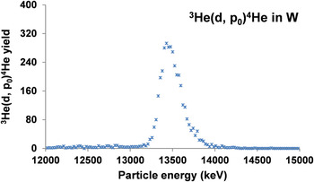
The first option is based on the simultaneous irradiation of a standard target with the investigated samples. The choice of the nature of this standard target is driven by the type and the energy of the incident ions used for the irradiation experiment. For example, in the case of an irradiation test performed with low energy heavy ions, a vitreous carbon matrix will be used and RBS postmeasurements will allow controlling the implanted dose. This approach has been mainly developed to qualify the irradiations conducted with transition metal ions (Ti, Fe) or gold and tungsten ions in various ceramics and alloys. On the opposite, in the case of light ion implantation (1H, 3He, 4He), a suitable metallic matrix (W thin foil, for example) will be simultaneously implanted and the dose will be checked, thanks to NRA or ERDA postmeasurements. Figure 10 shows a 900 keV deuteron induced NRA spectrum obtained for a 50 µm thin tungsten foil implanted with 1500 keV 3He ions at 15° of incidence at room temperature. Detection angle was 150° and a 23 µm thick mylar absorber foil was placed on the 1500 µm silicon surface barrier detector. The expected fluence was 1017 ions/cm2. Nine successive spectra were recorded in different areas of the tungsten foil. The mean value of the nine points gave a fluence of (1.02 ± 0.05) × 1017 3He/cm2. Reference Trocellier, Miro, Serruys, Vaubaillon, Pellegrino, Agarwal, Moll and Beck19
900 keV deuteron induced NRA spectrum obtained for a 50 µm thin tungsten foil implanted with 1500 keV three He ions at 15° of incidence at room temperature.

The two other options are based on RBS, ERDA, or NRA postmeasurements depending on the type, the energy, and the fluence of the implanted species. This approach has been followed to determine the initial depth distribution of hydrogen or helium (4He and 3He) ions as well as their evolution under internal or external physical parameters such as temperature, ion flux, ion dose, damage distribution, etc. Recent experimental developments have been focused on He profile characterization due to its interest for fission and fusion applications. Reference Trocellier, Agarwal and Miro39
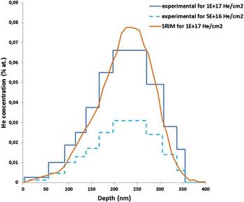
The chamber connected to Epiméthée has been upgraded to implement HI-ERDA for 4He analysis. Figure 11 illustrates the case of a pure α-iron pellet implanted with 60 keV 4He at room temperature. Helium depth profiles were extracted from 15 MeV 16O5+-induced ERDA measurements at 30°.
4He depth profile measured after implantation with 60 keV ions at room temperature in pure polycrystalline iron by using 15 MeV 16O5+-induced ERDA at 30°. Two fluences have been investigated: 5 × 10¹⁶ and 1 × 10¹⁷/cm2.

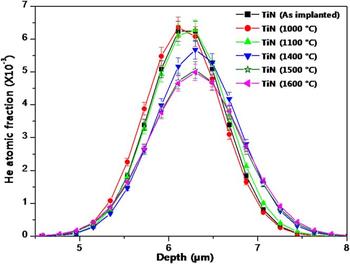
The 3He(d, p) NRA technique is used to study helium-3 mobility in inorganic compounds. This approach has been successfully applied to study helium mobility in SiC. Reference Miro, Costantini, Haussy, Beck, Vaubaillon, Pellegrino, Meis, Grob, Zhang and Weber40 Figure 12 allows comparing of the evolution of the 3He depth profile implanted in TiN after 2 hours-isothermal annealing tests carried out between 1000 and 1600 °C. From these curves, the extracted kinetic parameters of helium release show that TiN exhibits a very strong helium retention up to 1600 °C (less than 20% loss). Reference Agarwal, Trocellier, Serruys, Vaubaillon and Miro41 The 3He(d, p) NRA characterization has been then transposed to TiC and ZrC compounds. Reference Agarwal, Trocellier, Vaubaillon and Miro42
Helium depth profiles deduced from NRA measurements on samples implanted with 5 × 10¹⁶ 3 MeV 3He/cm2 at room temperature and annealed for two hours between 1000 and 1600 °C.

V. CONCLUSION
The JANNUS platform has been designed to study irradiation effects, ion beam modification of materials and to simulate neutron damage. At the JANNUS Saclay site, ion irradiation experiments have been conducted to emulate reactor irradiation damages by coupling three accelerators: A 3 MV Pelletron with an ECR source for heavy ion production and two lower energy accelerators for implanting gas ions such as H and He.
Since the first triple beam irradiation in 2010, continuous efforts have been made to implement ex situ and in situ characterization tools, to improve the quality of the irradiations as well as to provide characterization of radiation damage after or under irradiation. IBA methods such as RBS, ERDA, and NRA are now currently used to check the implanted dose received by the samples, to determine the initial implantation depth profile, and to measure the kinetic evolution of the depth profile as a function of the temperature, dose, pre or postdamaging. More recently, a Raman probe coupled to a Raman spectrometer has been installed in the triple beam chamber. In situ measurement of the radiation damage evolution in silicon carbide under irradiation with 4 MeV Au ions has been successfully achieved. Together with the JANNUS Orsay site which is dedicated to in situ TEM observation, Reference Serruys, Trocellier, Miro, Bordas, Ruault, Kaïtasov, Henry, Leseigneur, Bonnaillie, Pellegrino, Vaubaillon and Uriot7 the JANNUS platform proposes a full set of techniques for an accurate observation of radiation damage under irradiation. Application for beam time can be submitted every year through the national network EMIR (http://emir.in2p3.fr/).