1. Introduction
Safety and reliability are considered the most concerning indicators for a newly constructed building provided for living. Hollowness, as one of the major defects in non-destructive testing (NDT) area, has a profound impact on the safety of the overall structure with great difficulty for detection. The current method of manually detecting hollows is the chain-drag method [Reference Rehman, Ibrahim, Memon and Jameel1]. Since the floor space and height of buildings are growing more rapidly than in the past, the traditional manual detect methods have become difficult to cope with in terms of efficiency and accuracy. Therefore, a non-contact automated implementation system brings to necessary.
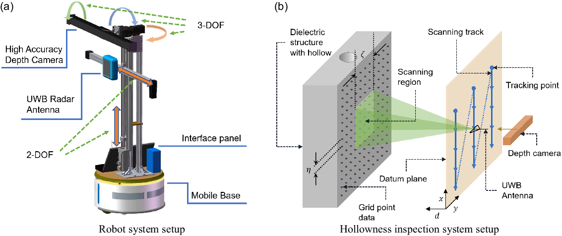
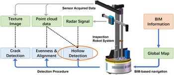
Currently, several kinds of hollow detection methods are realized by various solutions, including infrared thermography (IF) [Reference Cheng and Shen2–Reference Sham, Lo and Memon4], ultrasonic detection (UD) [Reference Azari, Nazarian and Yuan5], percussion method (PM) [Reference Chen, Montano, Huo, Fan and Song6], and microwave imaging (MI) through ultra-wide-band radar (UWB) [Reference Diamanti, Giannopoulos and Forde7–Reference Wu and He9]. UD can obtain the distance of different materials precisely but have strict requirements for coupling the sensors and the structure to be tested, which could lead to problems in complex-shaped structure automated detection scenarios. The PM can help detect floor hollows but lacks ease for walls. The IF method can detect structures within a certain distance. However, for most indoor scenarios, this method requires its heating source, which brings extra difficulties for design. And the hollowness depth is estimated by the temporal information of temperature and the model of heat transformation [Reference Cheng and Shen2, Reference Qu, Jiang and Zhang3]. For MI, with convenient air-coupled antennas selected [Reference Biswas, Ghatak and Poddar10, Reference Dong, Choi and Itoh11], the antenna can obtain the signal reflected by the inner target buried inside certain dielectric materials at a certain distance without being close to the structure. This brings the possibility of a robust automated system. The major challenge of MI is to obtain precise degree of arrival information with a simple antenna module, with the main lobe width as the azimuth resolution. Several methods, such as synthetic aperture radar (SAR) [Reference DeGraaf12] and range-point migration (RPM) algorithm [Reference Takahashi and Kidera8, Reference Akune, Kidera and Kirimoto13], are illustrated for high-resolution imaging without the usage of a complex antenna array, but both of them come with limitations. In this paper, we proposed an efficient automated system based on the combination of UWB radar and laser-based depth camera to obtain precise outer surface information of the dielectric structure and accurate hollow shape in point cloud form. The performance of our method is verified through simulation experiments. The system is integrated into the existing robot system to form a quality inspection robot capable of detecting hollows, cracks, evenness, and alignment parameters of prefabricated structures and constructed buildings. The robot system setup is illustrated in Fig. 1(a) and the hollowness inspection module in Fig. 1(b), and the total workflow of our inspection robot is illustrated in Fig. 2. In the next section, related methods, such as the original RPM algorithm, will be introduced briefly. The following sections will illustrate the algorithm details and experimental results of our Sensor Fusion-based hollow inspection system.
The system setup of the inspection robot. (a) The schematic of the robot system setup. (b) The experiment setup of hollow inspection system.

The total workflow of the quality inspection robot system.

2. Related works
2.1. Infrared thermography
IF is a global method mainly used for large surface area inspection [Reference Büyüköztürk14]. The traditional usage of this method is mainly aimed at the outdoor environment. After the structure absorbs the solar energy during the day, this method will be implemented for detecting the defects of the structure [Reference Sham, Lo and Memon4, Reference Stanley and Balendran15]. Yan et al. [Reference Yan16] introduced this method to the indoor environment by adding a heating source. The hollow defects can be observed through the difference in temperature between hollows, and solid concretes after being heated. This system can automatically retrieve the shape of hollow targets efficiently, but lacks depth information. The temperature changes inside the hollow region will be difficult to determine the depth of hollows and could be harmful to several specific construction materials.
2.2. Synthetic aperture radar
Currently, the widely used MI algorithm is mainly SAR algorithm [Reference Wu and He9, Reference Dvorsky, Al Qaseer and Zoughi17]. This algorithm can retrieve a high-resolution image without using a complex antenna array compared to the typical beamforming method. However, the principle of the SAR imaging algorithm determines its resolution is related to the pulse width of the radar signal [Reference Kidera, Sakamoto and Sato18]. The imaging resolution will significantly affect the detection accuracy for hollows buried inside the dielectric medium. Millimeter-wave radar [Reference ELsaadouny, Barowski, Jebramcik and Rolfes19, Reference Oka, Togo, Kukutsu and Nagatsuma20] can sort this problem partly, but the ability of penetration is limited by the frequency band and power.
2.3. Range-point migration algorithm
For the application that needs to draw dielectric-buried target images with high resolution and accuracy, Takahashi et al. proposed the RPM algorithm for outer surface imaging [Reference Kidera, Sakamoto and Sato18] and inner target detection [Reference Akune, Kidera and Kirimoto13].
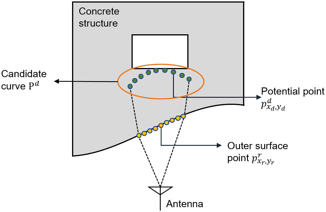
Compared with SAR, the RPM algorithm does not require beamforming operations. In contrast, the algorithm assumes that the target is on a curved surface known as candidate curves, with the receiving antenna as the center point and the optical path length of the echo signal as the radius, as shown in Fig. 4. It follows that the target boundary can be obtained from the intersection of multiple neighbored candidate curves after being weighted by Gaussian kernel [Reference Akune, Kidera and Kirimoto13].
The images obtained through this method have higher resolution and accuracy in estimating the target shape buried inside the dielectric medium. However, the echo signal density on the outer surface of the medium depends on the scanning interval of the scanning track, so the accuracy of curved surfaces used to estimate the target boundary points could be affected. Several modifications were implemented to the original algorithm to solve this problem, which led to better performance [Reference Takahashi and Kidera8, Reference Akiyama and Kidera21, Reference Kidera and Kirimoto22]. But at the same time, the normals of outer surface points are still calculated by the positions of receiving antenna and the boundary point itself.
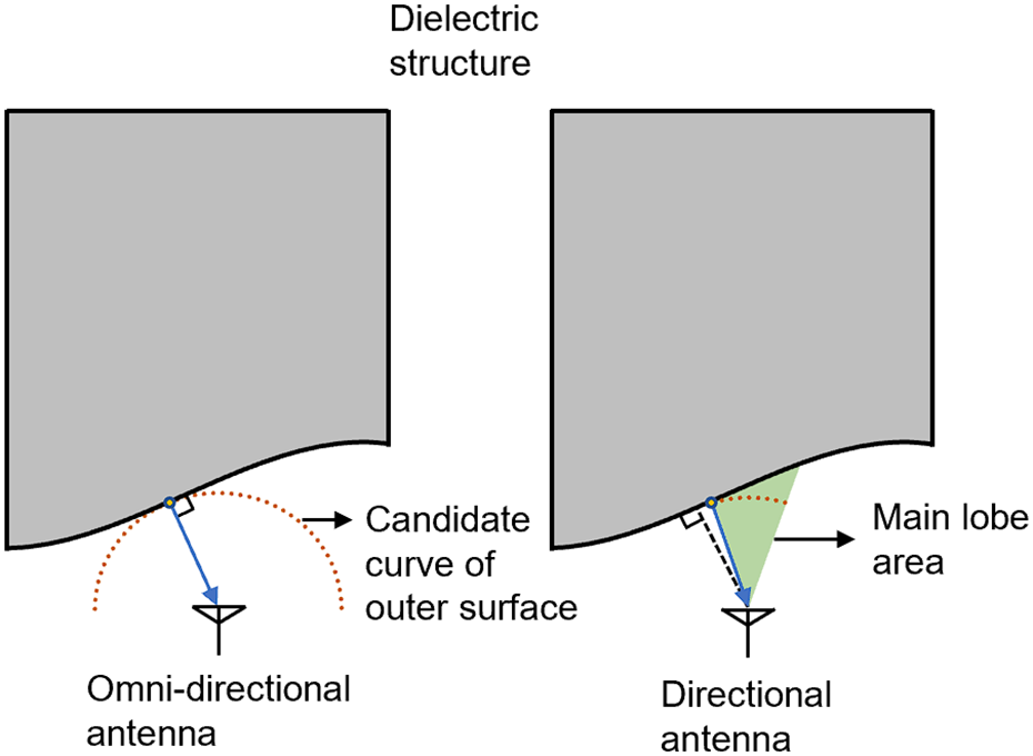
For omnidirectional antennas, this method will lead to reasonable results, given that the first-received signal will always reveal the shortest distance between the outer surface and the receive antenna. This leads to a natural vertical relationship between the candidate curve and the antenna. Thus, the normals can be obtained through the method introduced above. However, most air coupling antennas used in NDT always have a narrow main lobe with higher gain. This situation results in the reflected signal of each receive antenna and no longer reveals the vertical distance from the surface to the antenna, which leads to a normal with a wrong direction, as shown in Fig. 3. Moreover, with a complex-shaped surface, the scanning interval should be minimal for the calculation of dense outer surface data. This will lead to all normal vectors pointing directly to their nearest neighbored scanning position, and the time consumption will increase dramatically.
The comparison of outer surface point extraction procedure through original RPM algorithm with different antenna used.

The schematic diagram of the inner candidate curve and the outer surface points used in RPM algorithm. For targets buried inside dielectric structures, candidate travel paths should be calculated with refraction considered.

For the complex shape of the outer surface, this problem may seriously affect the accuracy of the detection results. Therefore, we will introduce an efficient system combining the original RPM algorithm with depth information extracted by a laser-based depth camera. This will improve the density of the outer surface data and the accuracy of their normals. By decoupling the extraction of the outer surface data and inner target information, the accuracy of the results is improved, and the system performs more efficiently. The detailed algorithm will be introduced in the next section.
3. Methodology
As mentioned previously, there are several problems that need to be solved:
-
Density of outer surface points.
-
Normal vector estimation.
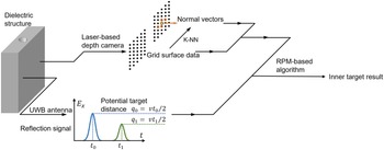
Several works will be mentioned to solve these problems in this section. The total work procedure is shown in Fig. 5, and the detailed method will be introduced below.
Schematic diagram of the overall workflow, the outer and inner data acquisition are decoupled.

3.1. Outer surface points acquisition
A laser-based depth camera is used to acquire more compressed point cloud data of the outer surface. Before the acquisition procedure, a datum plane for the experiment should be settled, as shown in Fig. 1(b). Then, the depth and location information of raw outer surface points
 $p_{{x_r},{y_r}}^r = ({x_r},{y_r},d_{{x_r},{y_r}}^r)$
can be obtained, in which
 ${x_r}$
and
 ${y_r}$
represent the
 $x$
and
 $y$
axis value of the raw point
 $p_{{x_r},{y_r}}^r$
, and
 $d_{{x_r},{y_r}}^r$
as the distance between
 $p_{{x_r},{y_r}}^r$
and the datum plane. The grid data
 $p_{r,c}^g = (r,c,d_{r,c}^g)$
will be obtained from the raw data through interpolation procedure, in which
 $r$
and
 $c$
still represent the
 $x$
and
 $y$
axis value of the grid point, but in uniform distance
 $\eta $
. In this form, the outer surface points will be in isometric distribution, and the density is guaranteed, leading to a smooth distribution of points in candidate curves.
3.2. Normal vector estimation
After obtaining the grid data of the outer surface points, the candidate curves for estimating the inner target shape will be calculated by the echo signal and outer surface data through Snell’s law. This requires normal information of the outer surface point being considered. The original RPM algorithm calculates the normal vector by generating a vector between the surface point and receiving antenna position and then normalizing it [Reference Kidera, Sakamoto and Sato18]. With our proposed method, the normal information of each outer surface point will be calculated through k-nearest neighbor (k-NN) based algorithm. Generally speaking, since raw point cloud data distribution is not quite uniform, the range selection of the k-NN method needs to be very careful [Reference Li, Chen and Zhu23]. With grid data, we calculate the normal
 ${n_{r,c}}$
of point
 $p_{r,c}^g$
from its 4 neighbored points through:
 \begin{align} {n_{r,c}} = e_{r,c}^v \times e_{r,c}^h \end{align}
in which
 \begin{align} & {e_{r,c}^v = e\!\left(p_{r + \eta ,c}^g,p_{r - \eta ,c}^g\right)} \nonumber \\[5pt] & {e_{r,c}^h = e\!\left(p_{r,c + \eta }^g,p_{r,c - \eta }^g\right)} \end{align}
The equation
 $e({p^a},{p^b})$
calculates the unit vector point from
 ${p^b}$
to
 ${p^a}$
. Compared with the original normal estimation scheme, this method can calculate more accurate normals of a complex shape outer surface.
3.3. Range-point migration-based algorithm
With outer surface points and normals acquired, the RPM algorithm will be implemented to calculate candidate curves of the inner target. First, the antenna will scan along the outer surface of the dielectric structure, as shown in Fig. 1(b). The scanning track is formed by a set of points
 $p_{r,c}^t = (r,c,d_{r,c}^t)$
which represent the projections of several grid data points
 $p_{r,c}^g$
. The distance
 $d_{r,c}^t$
between track points
 $p_{r,c}^t$
and datum plane is fixed and identical. For each track point
 $p_{r,c}^t$
, the potential inner target distance
 $q_i^{r,c}$
will be calculated through
 \begin{align} q_i^{r,c} = \frac{{vt_i^{r,c}}}{2} \end{align}
in which
 $t_i^{r,c}$
represents the time of travel of the potential inner target signal and
 $v$
to the travel speed of the microwave in free space. However, for targets buried inside the dielectric structure,
 $v$
will be influenced by the permittivity
 ${\varepsilon _r}$
of dielectric material. Thus, the revised travel path of the potential inner target signal should be obtained through Snell’s Law. At each
 $p_{r,c}^t$
in the track, a square region with side length
 $\zeta $
as shown in Fig. 1(b) will be considered as the scanning region of current scanning position, and the grid points inside this region will be considered as candidate junction points of echo signal received at that position. The potential points on the candidate curve
 ${{\bf{P}}^d}$
coupled with a certain scanning position will be calculated through Snell’s Law. Each potential point
 $p_{{x_d},{y_d}}^d$
on the candidate curve
 ${{\bf{P}}^d}$
coupled with track point
 $p_{{r_t},{c_t}}^t$
and candidate junction point
 $p_{{r_g},{c_g}}^g$
with inner target optical distance
 $q_i^{{r_t},{c_t}}$
will then be calculated by:
 \begin{align} {p_{{x_d},{y_d}}^d} & = Snell\!\left(p_{{r_t},{c_t}}^t,p_{{r_g},{c_g}}^g,q_i^{{r_t},{c_t}}\right) \nonumber \\[5pt] & = p_{{r_g},{c_g}}^g + \frac{{\left(q_i^{{r_t},{c_t}} - len\!\left(p_{{r_g},{c_g}}^g,p_{{r_t},{c_t}}^t\right)\right){{e}}_{{r_g},{c_g}}^d}}{{\sqrt {{\varepsilon _r}} }} \end{align}
in which
 \begin{align} {{e}}_{{r_g},{c_g}}^d = R\!\left(\!\mathop {\sin }\nolimits^{ - 1}\! \left(\frac{{{{{n}}_{{r_g},{c_g}}} \times {{e}}\!\left(p_{{r_t},{c_t}}^t,p_{{r_g},{c_g}}^g \right)}}{{\sqrt {{\varepsilon _r}} }}\right)\right)\!\left( -{{{n}}_{{r_g},{c_g}}}\right) \end{align}
the rotation matrix
 $R(\theta )$
is rotating along the normal vector of the plane formed by
 ${{{n}}_{{r_g},{c_g}}}$
and
 ${{e}}(p_{{r_t},{c_t}}^t,p_{{r_g},{c_g}}^g)$
, and
 $len({p^a},{p^b})$
calculates the Euclidean distance between these two points.
After the candidate curves of each scanning position are acquired, the intersection points considered as potential inner target points will be obtained. For each candidate curve coupled with a certain scanning position and potential target distance, the inner target points will be considered as the intersection points of the current curve and 2 of its 4 neighbored curves.
Instead of fitting the continuous form of curves, we assume that the intersection points are sets of points of the candidate curves. So the candidate point
 $p_{{x_d},{y_d}}^d$
of candidate curve
 ${\bf{P}}_i^d$
will be considered as intersection point
 $p_{x,y}^i$
if it satisfies:
 \begin{align} \exp = \left( {\frac{{ - w\!\left({p^d}_{\!\!\!xd,yd},{\textbf{P}}^{{d_1}}_{\!\!\!\!j}\;\right) - w\!\left({p^d}_{\!\!\!xd,yd},{\textbf{P}}_{k}^{{d_2}}\right)}}{{2{\sigma ^2}}}} \right) \ge \xi \end{align}
in which
 ${\textbf{P}}_j^{{d_1}}$
and
 ${\textbf{P}}_k^{{d_2}}$
are the 2 neighbored candidate curves of certain potential target distance and
 \begin{align} & {w\!\left(p_{{x_d},{y_d}}^d,{\textbf{P}}_j^{{d_1}}\right) = {\rm{min}}\;len\!\left(p_{{x_d},{y_d}}^d,p_{{x_d}_j,{y_d}_j}^{{d_j}}\right)}\nonumber \\[5pt] & {{\rm{for\;all}}\;p_{{x_d}_j,{y_d}_j}^{{d_j}} \in {\textbf{P}}_j^{{d_1}}} \end{align}
Here, a Gaussian kernel is implemented. Thus, the result will be considered as the possibility of each potential point being an inner target point. A certain threshold
 $\xi $
is set to determine the potential points. After a set of
 $p_{x,y}^i$
is obtained, the shape of inner target
 ${{\textbf{P}}^i}$
will be extracted. Like the RPM method itself, the original expressions of Eqs. (4)–(7) are from refs. [Reference Takahashi and Kidera8, Reference Akune, Kidera and Kirimoto13], and above are expressions that conform to the narrative logic of our proposed method.
4. Experiments
In this section, the performance of the hollow inspection system will be verified through several simulations, and specific evaluation indicators will be given. The first simulation experiment will evaluate the performance of the system when inspecting a structure with a complex surface. Several well-known and common-used structures are also considered to make the simulation experiment more reasonable. An experiment against a set of prefabricated concrete cubes is also performed to verify the performance of the actual system hardware, and the result will be analyzed in detail.
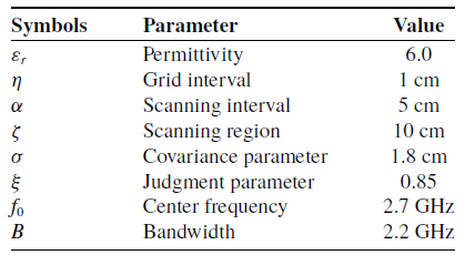
Simulation environment parameters.

4.1. Complex surface structure simulation
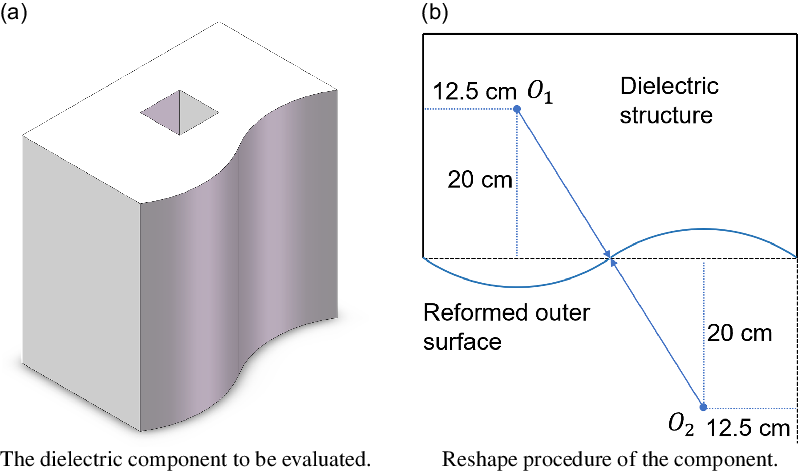
To evaluate our proposed method’s performance, a dielectric structure with a curved surface will be tested. The shape of the structure is shown in Fig. 8(a). The dielectric structure is based on a
 $50 \times 50 \times 30\;{\rm{cm}}$
cuboid with a
 $50 \times 10 \times 10\;{\rm{cm}}$
cuboid hollow buried at the center of the structure. Two arcs reform the structure’s front surface. Two circle centers
 ${O_1}$
and
 ${O_2}$
of the arcs are set on both sides of the original front surface, with an identical distance of
 $20\;{\rm{cm}}$
from the surface. The horizontal position of both centers is
 $12.5\;{\rm{cm}}$
away from their respective neighbored side surface, as shown in Fig. 8(b). The radius of both arcs will be calculated by:
 \begin{align} R = \frac{{len({O_1},{O_2})}}{2} \end{align}
and the front surface will then be reshaped.
The datum plane is set to have all points on it, located with
 ${d} = 0$
, and the origin point
 $(0,0,0)$
is set in the corner of the datum plane, as shown in Fig. 1(b). In order to simulate the situation of detecting real concrete walls, the main parameters of this experiment are set as shown in Table I. The grid interval of raw outer surface data
 $\eta $
is
 $1\;{\rm{cm}}$
.
 $10 \times 10$
scanning track points are overlapped on the datum plane with
 $5{\rm{cm}}$
as scanning interval
 $\alpha $
along
 $x$
and
 $y$
axis. The transmit and receive antennas are considered to be directional air-coupled antennas, so the scanning region parameter
 $\zeta $
is set to be
 $10\;{\rm{cm}}$
. The transmit and receive antennas are overlapped on track points and scan along the track as shown in Fig. 1(b) from start point
 $(47,2,0)$
to endpoint
 $(2,47,0)$
. A Gaussian pulse will be transmitted at each point, and the reflected signal will be received. The Gaussian-modulated pulse is formed with a center frequency of 2.7 GHz, effective bandwidth of 2.2 GHz and is linearly excited along the
 $x$
axis. The dielectric structure will be located with its hollow center at
 $(25,25,45)$
, and the front curved surface faces the datum plane. The dielectric medium is assumed to be homogeneous and lossy concrete material, with a relative permittivity of
 $6.0$
and conductivity of
 $0.001{\rm{S/m}}$
. The material of hollow buried inside the medium is considered to be air. The comparison parameter
 $\xi $
is used to determine the potential target points. In this experiment, the distance between potential points and the candidate curves will be expected to be less than
 $1\;{\rm{cm}}$
. Thus,
 $\xi $
is set to
 $0.85$
. The simulation is powered by Meep [Reference Oskooi24], the space resolution is set to
 $1\;{\rm{cm}}$
, and the wave-traveling resolution is set to be half of the space resolution per time step.
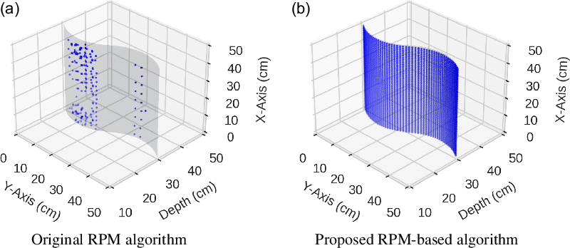
The outer surface points extracted through both methods. The gray curved surface is the real front outer surface. The blue points are results of both methods.

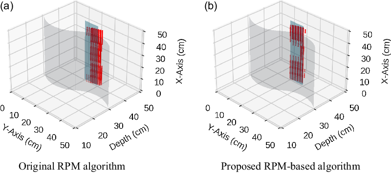
The inner target surface points extracted through both method. The gray curved surface is the real front outer surface; the blue plane is the real inner target front surface. The red points are results of both methods, which are calculated with the same outer surface data shown in Fig. 6(b). The outer surface normals are calculated in different ways.

The dielectric component with hollow defect buried inside. (a). The overall view of the component. (b). The reshaping procedure of the front surface of component.

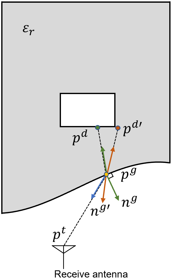
Illustration of the impact of false normal to potential target point.
 ${n^g}$
and
 ${n^{g{\prime}}}$
represent real and false normal, respectively, the potential point calculated by
 ${n^{g{\prime}}}$
shows a noticeable shift from the real one
 ${p^d}$
.

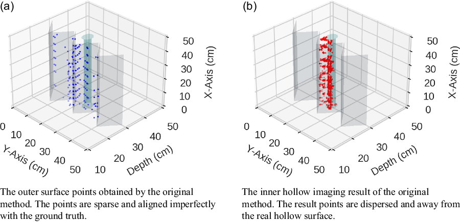
With the environment settled before, both methods are implemented. First, the outer surface points extracted by both methods are illustrated in Fig. 6. The original method calculates the outer surface points by comparing the distance of several candidate curves generated through the first-received signal. Those points with a small distance to neighbored candidate curves will be considered outer surface points. This method will affect the density of outer points by the scanning interval. As shown in Fig. 6, the data extracted through the original method failed to cover the center region of the complex surface. With no outer surface point covered in this region, the candidate curve of inner target coupling with this scanning region could not be calculated, given that there is no junction point in this blank region. This results in the inner target shape being undiscovered with the original method implemented. By decreasing the scanning interval with a narrow lobe width antenna, the density and accuracy of outer surface data will increase. The normals, however, will be more inaccurate, as derived before in Section 2.
For a more comparable result, outer surface data of the proposed method will be used to evaluate the original method. The data could be considered as results calculated with the setup illustrated above, and the normals will be set to point directly to the datum plane. The simulation results of both methods are shown in Fig. 7. For the result of the original method, a significant shift from the ground truth can be observed, and the result of the proposed method reveals a more accurate position of the inner target boundary. This reveals the influence of normal vectors on the candidate curve estimation and, eventually, on the result. As shown in Fig. 9, the final position of candidate point is related to the potential distance
 ${q}$
and normal vector
 ${\bf{n}}$
. With a complex outer boundary shape, the false normal vector will lead to a significant error in estimating the potential travel path of the reflected signal, which will lead to a shift in the candidate point.
For a quantitative evaluation, two metrics are defined:
 \begin{align} s = center({{\textbf{P}}^{res}}) - center({{\textbf{P}}^{truth}}) \end{align}
 \begin{align} r = 1- \frac{\sum^{N}_{i=1}\lfloor len(p^{res}_{i},p^{truth}_{i})/\tau \rfloor}{N} \end{align}
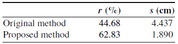
The first metric compares the center of result points to the real center of the inner target surface. The second one calculates the ratio of valid result points judged by threshold
 $\tau $
. The values of metrics calculated with
 $\tau $
set to
 $1\;{\rm{cm}}$
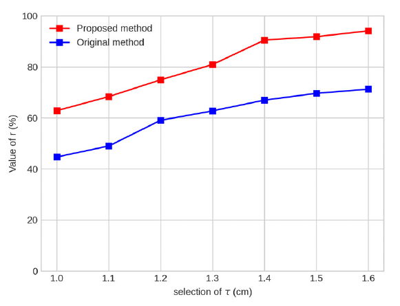
are illustrated in Table II. The selection of threshold
 $\tau $
should be careful, given that the error increases with a higher
 $\tau $
, so the comparison of
 $r$
with different
 $\tau $
selected from
 $1$
to
 $1.6$
cm with an interval of
 $0.1\;{\rm{cm}}$
is implemented, as Fig. 10 shows. It reveals that a higher threshold will increase the ratio of result points to be considered as real target points.
Evaluation of simulation results with
 $\tau = 1$
.

Ratio
 $r$
of valid result points with
 $\tau $
from 1 to 1.6.

4.2. Commonly used structure simulation
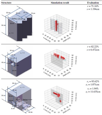
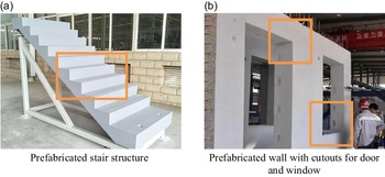
To test the performance of the system more convincingly, a series of prefabricated components common in the construction industry were added to the simulation test. As shown in Fig. 12, Fig. 12(a) is a prefabricated stair structure commonly used in the construction industry, and Fig. 12(b) is a wall structure with cutouts for door and window. To simulate the performance of the system in the actual detection scene, we adopted several structures, as shown in Table III as the detection objects of the simulation test. The structure details and simulation test results are presented in Table III. The simulation test environment settings will use the data from Table I.
Commonly used structures and simulation experiments results.

As shown in Table III, each structure used for the simulation experiments has hollows located near the edges. This is because, in reality, it is easier to generate hollows and other damages at the joints of the mold when pouring concrete, and these hollows are relatively difficult to detect. According to the experimental results in Table III, it can be seen that the hollow detection at the seam is more complicated than others. The detection result of the hollow in the stair structure is relatively accurate. However, the imaging result is not ideal because of the lack of reflection signals from the stair-shaped surface. The experiments on the hollows at the corners of the wall can make a good image of one of the hollows, but the detection result of the other hollow with a slightly complex shape has a significant deviation. At the same time, compared with the hollow detection result near the cutout of the window, it can be seen that the imaging accuracy of the hollow structures at the edge of the concrete structure is limited by the part of the signal that reaches the receiving antenna after multiple reflections at the edge of the structure. This question will be a focus of future research.
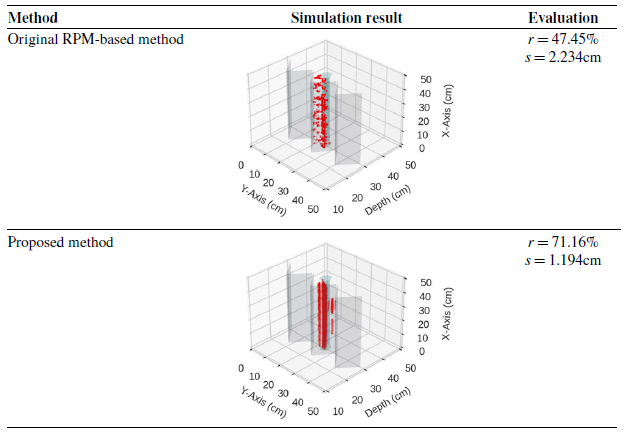
To better compare the performance of the proposed method with the original one, the stair structure is used as the experimental object. The simulation results are shown in Fig. 11, in which the acquisition method of the outer surface point of the structure and its normal comes from refs. [Reference Akune, Kidera and Kirimoto13, Reference Akiyama and Kidera21]. In Fig. 11(a), the outer surface points acquired by the original method are illustrated. The outer points are sparse and not accurately laying on the ground truth, which could be caused by the complexity of the stair structure surface. As shown in Table IV, the result of the 2 methods is compared. The imaging result of the hollow acquired by the original method is more dispersed and inaccurate. The result of the proposed method is more concentrated around the ground truth of the buried hollow. The evaluation metrics of both results are shown in Table IV. The proposed method outperforms the original one in both metrics. The error and shift of the original method could be caused by the sparsity of the outer surface points and the acquisition method of the surface point normal, both optimized in our proposed method.
The simulation result of the original method against the stair structure.

The commonly used structures in real building scenarios.

Commonly used structures and simulation experiments results.

4.3. Concrete structure experiment
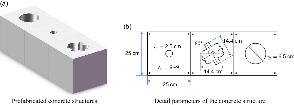
In order to verify the performance of the actual hardware system, a group of concrete structures containing artificial hollows was used for the experiment. The overall schematic diagram and detailed parameters of the concrete structures can be seen in Fig. 13. Three identical concrete cubes form the concrete structure with different hollows. The parameter of two cylinder hollows can be seen in Fig. 13. The complex-shaped hollow is formed by three ellipses and a rectangle. The length of the rectangle is 14.4 cm. The semi-major and semi-minor axes are 7.2 and 3.2 cm, respectively. The angle between neighbored ellipse is
 ${\rm{3}}{{\rm{0}}^ \circ }$
and the angle between the rectangle and the neighbored ellipse is
 ${\rm{6}}{{\rm{0}}^ \circ }$
, as shown in Fig. 13. In this experiment, the Photoneo XL high-precision scanner was used to extract the point cloud data of the external surface of the structure. The radar adopts a self-developed radar with a center frequency of 2700 MHz and a bandwidth of 1500 MHz. The width of the antenna’s main lobe is
 ${\rm{4}}{{\rm{5}}^ \circ }$
horizontally and
 ${\rm{5}}{{\rm{0}}^ \circ }$
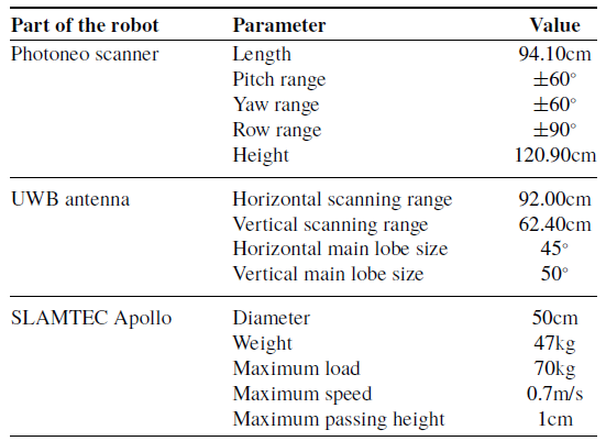
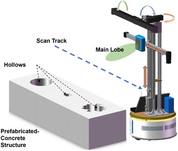
vertically. The detailed datasheet of the autonomous inspection robot is shown in Table V. The experimental design is that the robot will travel along several positions around the concrete structure, which the user gives. At each position, the radar antenna scans along the center-line of the structure with a fixed interval on the horizontal scanning route, obtains the data of each sampling point, and then combines the point cloud information to calculate the hollow 2D image. The experimental setup is shown in Fig. 14. The experimental results are shown in Fig. 15.
The schematic diagram of used concrete structure.

Autonomous NDT robot system parameters.

The schematic diagram of the experiment setup.

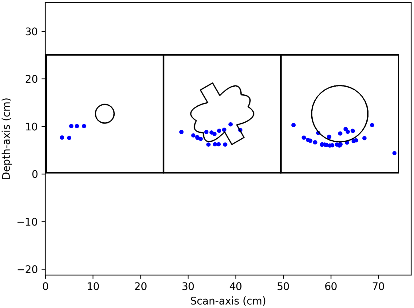
The result of the experiment, in which those blue points represent the imaging result. The experiment result shows the hollow with complex shape is difficult to imaging.

The experimental result Fig. 15 shows that the system can detect one of those artificial hollows with a relatively regular shape. However, the detection results of the hollow with complex shapes are not ideal, and the small hollow is completely undetected because of the lack of solid reflection signals. In Fig. 15, some hollow results do not coincide with the ground truth in the first cube. The reason is that the sand and gravel doped with the concrete structure used in this experiment are not uniform enough, and the size of some stones is too large, so the reflected signals are treated as hollow reflection signals. The uniformity problem also leads to the difficulty of choosing a proper dielectric value
 ${\varepsilon _r}$
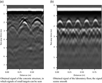
for the concrete structure, which leads to a shift in the imaging result of the third hollow. For comparison, Fig. 16(a) shows the echo signal of the experimental concrete structure, and Fig. 16(b) shows the signal of our laboratory floor. It can be seen that the properties of materials used in conventional engineering are uniform, and there is no similar problem. This experiment proves that the hollow monitoring system can work under real conditions. However, the imaging effect is not ideal for hollows with highly complex shapes. It can be seen from the experimental results that the accuracy of the actual detection results will be limited by the material properties of the structure to be detected and the impact on prior knowledge of its dielectric properties.
The comparison of signals reflected from the concrete structure and the floor. The true position of the tiles inside the floor remains unknown so there is no experiment produced on it.

5. Conclusion
In this experiment, we derived an efficient hollow detection automated system. By decoupling the acquisition of outer surface and inner target information, the system based on the proposed method performs more accurately than with the original method. Considering that the outer surface point and inner target information are now obtained through different hardware, the entire workflow can now be split into two and work simultaneously. Thus, the system can perform more efficiently. Since the laser scanner is able to obtain accurate outer surface information, its sampling rate is reduced to eliminate the error by sliding structure.
Two evaluation metrics are used for comparison, and our proposed method shows great advantage in the simulation experiment. The result of our proposed method shows better alignment and density compared to the original one. On the one hand, the simulation experiments of common structures confirm the availability of the system in reality. On the other hand, it shows that the system still has problems to be solved, such as the ability of hollow detection at the edge of the structure, which is caused by the signal bouncing inside the structure multiple times.
The robot system experiment verifies the practicability of the hardware system and points out the limitations of inspecting the real structure, such as the uniformity of the detected structure material. Considering that the outer surface of the prefabricated concrete structure is planar surface, the comparison result of the original method and our proposed method is not performed. The difference between the experimental results is not quite significant. In the future, more experiments will be performed to improve the current hollow inspection system, and the modifications will target the abovementioned problems.
Author contributions
In this paper, Haoran Kang contributed to the hollowness detection algorithm as well as the related experiments. Wentao Zhang contributed to the robot hardware design and assembly. Yangtao Ge and Bangzhen Huang contributed to the design of the structures used in simulations. Haiou Liao participated in the acquisition of the experimental data and designed the structures used in it. I-Ming Chen, Jing Wu and Rui-Jun Yan provided a lot of guidance during the experiment and provided a lot of help in the writing of the article.
Financial support
This material is based upon work supported by the National Science Foundation of China #U1913603 and #62203205. The views, opinions, findings and conclusions reflected in this publication are solely those of the authors and do not represent the official policy or position of the NFSC.
Conflicts of interest
The authors declare no conflicts of interest exist.
Ethical approval
Not applicable.