Introduction
With the development of communication systems, more and more multi-band antennas are used in modern communication equipments [Reference Wang, Kong, Li and Du1]. There are many ways to achieve multi-band operation such as adding resonators [Reference Qian, Chen, Xiang and Chu2–Reference Liu, Wen, Zhu, Ren, Guan and Yu7], using multi monopoles or dipoles [Reference Xu, Li, Liu and Liu8–Reference Yang, Zhang, Li, Zhang and Pedersen13], etching slots [Reference Hsu and Chung14–Reference Ali, Fatima and Biradar18], and so forth.
Many designs are based on the aforementioned methods. For instance, Luo et al. [Reference Luo, Zhu, Liu, Liu and Gong5] designed a multi-band antenna by adding L-type branches exciting multiple modes. Cao et al. [Reference Cao, Cheung and Yuk6] used a T-shaped feeding patch to generate two frequency bands, and by adding stubs, a quad-band slot antenna was realized. Liu et al. [Reference Liu, Wen, Zhu, Ren, Guan and Yu7] designed a quad-band antenna with the help of five-pointed star structure. These antennas provide multi-band operation by increasing the number of radiators. But they are not of circular polarization (CP).
For the multi monopole/dipole technique, there are also many designs. An antenna composed of three monopoles of different shapes was reported in [Reference Sreelakshmi, Rao and Kumar11]. The three monopoles worked together to generate three frequency bands, being useful for Bluetooth, 5G, and WLAN. Kasmaei et al. [Reference Kasmaei, Zareian-Jahromi, Basiri and Mashayekhi12] designed a tri-band antenna by using monopoles and metamaterials. The impedance bandwidths are 25.8, 26.8 and 4.2%, which can be used for 3G, WiMAX and WLAN. Yang et al. [Reference Yang, Zhang, Li, Zhang and Pedersen13] designed a quad-band magneto-electric (ME) dipole antenna by adding bent metal plats on the dipole. This is a good way to realize multi-band antenna. Unfortunately, the disadvantage lies in the difficulty of miniaturization. These antennas usually have relatively large size.
Etching slot method is another common method. Li et al. [Reference Li, Du, Yang and Gao17] introduced two slots of different shape on a circular patch, in this way a quad-band wearable patch antenna was realized. And the impedance bandwidths reach 3.67, 5.72, 5.85 and 9.74%, respectively. Ali et al. [Reference Ali, Fatima and Biradar18] designed a multi-band antenna by carving grooves on the ground plane, which could generate five frequency bands with impedance bandwidths of 11.5, 9.9, 13.4, 4 and 9.05%, respectively. Grooving on the ground layer is a good approach to design of multi-band antennas, but the impedance bandwidth of these antennas is not sufficiently wide.
There are also many other methods. For instance, using frequency selective surface (FSS), linearly polarized signals can be converted into circularly polarized signals. In this way, a quad-band antenna was designed [Reference Hoang, Le, Li and Park19]. Mao et al. designed multi-band antenna through coupled resonator network [Reference Mao, Gao, Wang and Sanz-Izquierdo20]. While achieving multi-band, these antennas also increase the complexity of the antenna structure.
Actually, there are three types of antenna polarization, linear polarization (LP), CP, and elliptical polarization [Reference Zhu, Cheung, Liu and Yuk21, Reference Ni, Chen, Zhang and Wu22]. Circularly polarized antennas are widely used in global navigation satellite system due to orientation-independent characteristics, low multipath effect [Reference Sharma, Das, Gupta and Gangwar23], and not affected by the Faraday rotation [Reference Feng, Chen, Xue and Shi24, Reference Zhong, Zhang, Liang, Han, Fan, Huang, Xu and Yuan25]. Moreover, the dual-band circularly polarized antenna can improve the accuracy of positioning. In contrast, an LP antenna is relatively simpler than CP antenna to be realized [Reference Singh, Agarwal, Pandey and Meshram26]. Therefore, multi-frequency CP, especially the hybrid application design including CP and LP for different frequency band is even more challenging.
In this paper, a multi-band rectangular slot antenna for BDS/4G/WLAN/5G is proposed to combine both CP and LP to one single antenna. The antenna consists of three c-type resonators and three rectangular slots with different widths to generate five frequency bands at about 1.2, 1.56, 2.5, 3.6, 4.5 GHz. Multiple frequency bands can be generated by increasing the number of resonators and rectangular loop slots. The polarization mode of this antenna is right hand circular polarization (RHCP) in the BDS frequency bands, and LP in the 4G, WLAN, and 5G frequency bands. This multi-band antenna has a simple structure without needing of an additional feeding network, which is much preferred in wireless communication equipment.
Antenna design
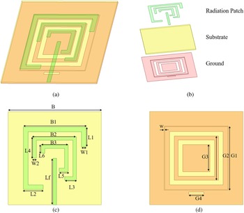
The structure of the proposed antenna is illustrated in Fig. 1. The antenna consists of a 50-Ω microstrip feeding line, three c-type resonators, three rectangular loop slots with different widths and a rectangular slot under the feeding line. Three c-type resonate rings are printed on the top layer of a 1.6 mm thick FR4 substrate with a relative permittivity of 4.4 and a loss tangent of 0.02, while the three rectangular slots are etched on the bottom layer of this substrate. The overall size of the antenna is B × B × H. To determine the final structure of the antenna, the antenna is modeled and simulated in the commercial software HFSS. The optimized dimensions of the proposed antenna are shown in Table 1.
Geometry of the proposed antenna. (a) 3D structure diagram; (b) Structural exploded diagram; (c) Radiation patch; (d) Ground plane.

Dimension of the proposed antenna (unit: mm)

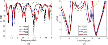
The evolution of the multi-band antenna design is shown in Fig. 2. The AR and impedance bandwidth of Ant.1–Ant.4 are plotted in Fig. 3.
The evolution process of the antenna.

Simulated S 11 and AR for Ant.1- Ant.4. (a) S 11; (b) AR.

It is seen that Ant.1 consists of a 50-Ω microstrip feeding line, a c-type resonator and a rectangular loop slot, which can generate two frequency bands at about 1.2 and 2.1 GHz. The resonant frequency of the antenna is determined by the length of the resonant element and can be calculated according to the following equations. For Ant.1, the length of the resonant element can be written as

The corresponding resonant frequency can be estimated using

where c is the speed of light, and $\varepsilon _{{\rm eff}} = ( \varepsilon _{\rm r} + 1) /2$ . The calculated result reads f 1 = 1.22 GHz, which is very close to the simulated results, where the first resonance takes place at 1.215 GHz. The equivalent circuit of Ant.1 is shown in Fig. 4. The antenna radiation element is represented by R 1 and L 1. R 1 refers to the radiation loss of the antenna, L 1 stands for the inductance of the ring, C 1 denotes the terminal capacitor, and C 2 refers to the capacitor generated by the ground groove [Reference Kasmaei, Zareian-Jahromi, Basiri and Mashayekhi12].
Equivalent circuit for the c-type ring.

The axial ratio of Ant.1 is much greater than 3 dB and its polarization mode is LP. On the basis of Ant.1, a resonator and a rectangular slot are added and Ant.2 is formed. The second resonant frequency of Ant.2 is determined by the length of the second resonant element

By using

one obtains $f_2 = 1.68\;GHz$ , which is also in the second range 1.50–1.75 GHz.
It can be seen from the simulation results that the reflection coefficient and the axial ratio are decreased. The axial ratio is less than 3 dB at 1.18 and 1.56 GHz, which can be applied to Beidou satellite navigation system (BDS). In order to increase the number of frequency bands, a small resonator on the inside and a rectangular slot with a width of w on the outermost side are added, see Ant.3. The axial bandwidth is shifted to the right, which can cover BDS B1 and B2 frequency bands. And the impedance bandwidth of the proposed antenna has been greatly improved. However, the impedance bandwidth is still a bit narrow and cannot fully cover WLAN and 5G frequency bands. Therefore, another rectangular slot on the ground is added to the antenna, see Ant.4. In this way, we obtain a multi-band rectangular slot antenna that can be used in BDS, 4G, WLAN, 5G.
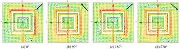
The two frequency bands of Beidou satellite navigation system (BDS) are B1 1561.098 MHz and B2 1207.14 MHz, respectively. The c-type resonant unit affects the current distribution around the ring gap, generating two orthogonal polarization modes with a phase difference of 90° between x and y directions, thus exciting CP radiation. By adjusting the length of the c-type resonant unit, 3 dB axial ratio can be obtained. From the current distribution diagram, the sense of CP can be detected. The surface current distributions of 0°, 90°, 180° and 270° at 1.2 GHz show in Fig. 5. It can be seen that the current rotates clockwisely as the phase increases, indicating that the antenna radiates left-hand circularly polarized (LHCP) waves at 1.2 GHz.
Distribution diagram of antenna surface current changing with phase at 1.2 GHz. (a) 0°; (b) 90°; (c) 180°; (d) 270°.

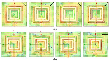
The polarization mode of an antenna in satellite navigation system is right-handed circular polarization (RHCP). In order to adjust the polarization of the antenna to right-hand circular polarization, the first resonant ring is rotated by 90° as shown in Fig. 6(b). The current distribution of the antenna also changes after the modification. The current distributions of 0°, 90°, 180°, 270° at 1.2 GHz are plotted in Fig. 7(a). And the current distributions of 0°, 90°, 180°, 270° at 1.56 GHz is shown in Fig. 7(b). It can be found that the current rotates counterclockwisely as the phase increases, implying that the antenna radiates right-hand circularly polarized (RHCP) waves at 1.2 and 1.56 GHz.
Structure change of the antenna. (a) Initial structure; (b) Final structure.

Surface current distributions of the proposed antenna at (a) 1.2 GHz; (b) 1.56 GHz.

From the current distribution diagram, one can see the corresponding relationship between the antenna structure and the frequency band. The current is mainly distributed on the first resonator at 1.2 GHz, which means that the frequency band at 1.2 GHz is dominantly affected by the first resonator, being in line with equation (2). Similarly, the current is mainly distributed on the second resonator at 1.56 GHz.
The simulation results of the final structural are shown in Fig. 8. There are five frequency bands with reflection coefficient less than −10 dB, which is sufficiently good for BDS L 1, BDS L 2, 4G, WLAN and 5G. Moreover, the axial ratios in the BDS frequency bands are better than 3 dB.
The simulation result of the antenna. (a) S 11; (b) AR.

Parameter study
From the evolution process, it is recognized that the number of frequency bands increases with the number of resonators and rectangular slots. Changing the length of the outermost resonators can generate two orthogonal modes with the same amplitude and a phase difference of 90°, realizing circularly polarized radiation. And the lowermost rectangular slot can significantly improve the bandwidth of the multi-band antenna. Therefore, the parameters of the above structures are analyzed.
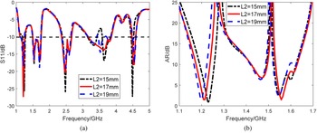
The first parameter sweep is performed on the length of the first resonator L 2. The simulation results of reflection coefficient and axial ratio are shown in Fig. 9. From Fig. 9(a), one can see that the length of L 2 only affects the fourth frequency band. When L 2 becomes longer or shorter, the bandwidth of the fourth frequency band will become smaller. As shown in Fig. 9(b), with the length of L 2 increases the axial ratio frequency band shifts to the left. In addition, the axial ratio increase. In order to enable the fourth frequency band to fully cover the 5G N78 (3300–3800 MHz) band, while not compromising the performance of other CP bands, L 2 = 17 mm is chosen.
Effect of L 2 on antenna performance. (a) S 11; (b) AR.

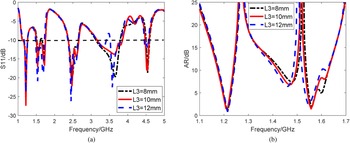
The simulation results of reflection coefficient and axial ratio versus the change of L 3 are plotted in Fig. 10. As L 3 increases, the reflection coefficient in the second frequency band becomes smaller, but the axial ratio becomes larger. And when L 3 = 12 mm, the impedance bandwidth of the fourth frequency band is decreased. Therefore, we choose L 3 = 10 mm to meet BDS and 5G requirements.
Effect of L 3 on antenna performance. (a) S 11; (b) AR.

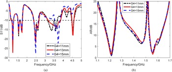
It is seen in the previous section that the rectangular slot also affects the impedance bandwidth. When G 4 = 11 mm, the impedance bandwidth of the fourth frequency band is decreased. When G 4 = 15 mm, the antenna has only four frequency bands. From Fig. 11(b) it is seen that the length of G 4 has little effect on the axial ratio. Therefore, the size of rectangular slot is fixed at G 4 = 13 mm.
Effect of G 4 on antenna performance. (a) S 11; (b) AR.

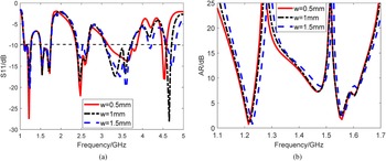
Finally, the width of the rectangular loop slot w is also studied, and the results are plotted in Fig. 12, where it is seen that w has similar effect on the impedance bandwidth as L 2. When w = 0.5 mm, the impendence bandwidth is widest. As w increases the axial ratio frequency bands shift to the right. Adjusting the values of L 2 and w appropriately, one can get a suitable axial ratio over the operation frequency band.
Effect of w on antenna performance. (a) S 11; (b) AR.

Results and discussion
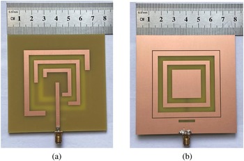
After optimization, the antenna is fabricated based on PCB technologies, as shown in Fig. 13.
Antenna real picture. (a) Top layer; (b) Bottom layer.

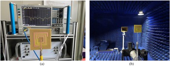
The measurement on S 11 is conducted using a calibrated vector network analyzer. And the far-field parameters and gain are measured in a microwave anechoic chamber (Fig. 14).
Antenna measurement. (a) S 11; (b) Far field.

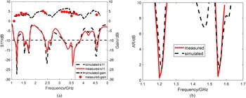
It can be seen from Fig. 15 that the simulated and measured impedance bandwidth, axial ratio bandwidth and gain are in good agreement with simulated ones. The measured impedance bandwidths at 1.2, 1.56, 2.5, 3.6 and 4.5 GHz are 11.8% (1.12–1.26 GHz), 15.4% (1.5–1.75 GHz), 11.9% (2.36–2.66 GHz), 19.7% (3.15–3.84 GHz) and 2.6% (4.47–4.59 GHz), respectively. The measured 3 dB AR bandwidths are 20 MHz at 1.2 and 1.56 GHz, which can fully cover BDS B1and B2 bands. The measured gains are 3, 3.59, 4.07, 4.2 and 4.35 dBi, respectively.
Comparison of simulation and measured results. (a) S 11 and Gain; (b) AR.

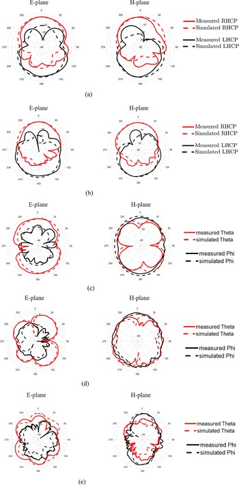
The antenna radiation patterns are shown in Fig. 16. For 1.2 and 1.56 GHz, circularly polarized radiation patterns are presented. As can be seen from Figs 16(a) and 16(b) the antenna radiates right-handed circularly polarized waves in the direction of wave propagation.
The simulated and measured radiation patterns in E plane and H plane at (a) 1.2 GHz; (b) 1.56 GHz; (c) 2.5 GHz; (d) 3.6 GHz; (e) 4.5 GHz.

A comparison of this work with the designs in the literature is shown in Table 2. Compared with existing multi-band antennas, several merits of this design can be found. First, the antenna has five frequency bands and their bandwidths are wide enough, covering BDS, WLAN, 4G, 5G systems. Second, the antenna includes two polarization modes: LP and CP. The Beidou satellite navigation system requires the transmitting and receiving antennas to be circularly polarized. And the proposed antenna can well meet these requirements. In addition, in 4G, WLAN, and 5G frequency bands, the polarization modes of the antenna are LP. Third, this antenna is simple with low cost in fabrication.
Comparison of the multi-band antennas

Conclusion
A multi-band microstrip antenna for BDS,4G, WLAN, 5G applications was designed, fabricated and measured in this paper. CP is achieved at 1.2 and 1.56 GHz by changing the length of the resonator. By increasing the number of the resonator and rectangular slots, multi-band operation is realized. The measured impedance bandwidths at 1.2, 1.56, 2.5, 3.6 and 4.5 GHz are 11.8, 15.4, 11.9, 19.7 and 2.6%, respectively. The measured 3 dB AR bandwidths are 20 MHz at 1.2 and 1.56 GHz, which can fully cover BDS B1 and B2 bands. A simple structure with a single feeding line is used to realize both CP and LP to a single antenna.
Data
Not applicable.
Acknowledgements
This work is funded in part by, the University Synergy Innovation Program of Anhui Province (GXXT-2021-027), the National Natural Science Foundation of China (61871003, 62101005), the Natural Science Foundation of Anhui province (No. 2108085QF256), the open project of the state key laboratory of complex electromagnetic environment effects on electronics and information system (CEMEE2022Z0201B) and Natural Science Research Project for Universities in Anhui Province (KJ2021A0101).
Author contributions
H. Wang and X. Yang did the design and simulation, Z. Fang and Y. Wang performed the measurement, R. Zhang plotted the figures, X. Liu prepared and reviewed the manuscripts, X. Liu, X. Yang, R. Zhang, and Y. Wang provided fundings.
Conflict of interest
The authors report no conflict of interest.
 Haiyang Wang received the bachelor's degree in electronic information engineering from Anhui Normal University, Wuhu, Anhui, China, in 2020. He is currently pursuing the degree with the School of Physics and Electronic Information, Anhui Normal University, Wuhu, China. His research focuses on circular polarized antenna design.
 Xiaoming Liu received the B.Sc. degree in applied physics in Nanjing University of Posts and Telecommunications in 2006, Nanjing, China, and Ph.D. degree in 2012 in electronic engineering at the School of Electronic Engineering and Computer Science, Queen Mary University of London, London, UK. In 2012, he joined the School of Electronic Engineering, Beijing University of Posts and Telecommunications. He is now with the School of Physics and Electronic Information, Anhui Normal University. His research interests include terahertz science and technology, quasi-optical techniques and systems, millimeter and sub-millimeter wave antenna measurement techniques and bio-electromagnetics.
 Xiaofan Yang received the Ph.D. degree in 2012 in electromagnetic and microwave technology at the School of Electronic Science and Engineering, University of Electronic Science and Technology of China. During the period as a doctoral student, he joined the EHF Key Laboratory of Fundamental Science, University of Electronic Science and Technology of China. From 2011 to 2012, he has been titled as visiting scientist to RAL Space, Rutherford Appleton Laboratory, Science and Technology Facilities Council, at Oxford, UK. He is now with the State Key Laboratory of Complex Electromagnetic Environment Effects on Electronics and Information System, Luoyang Electronic Equipment Test Center of China. His research interests include terahertz science and technology, electromagnetic wave propagation, millimeter and sub-millimeter wave receiver front-end.
 Zhibin Fang, Senior Engineer, received the B.Sc. degree in automation major in Guangdong University of Technology in 2003, China, and Master of Science in Engineering in 2020 in School of Business Administration, South China University of Technology, China. He is now working in China Electronic Product Reliability and Environmental Testing Research Institute. His research interests include Quality and Reliability, Automatic control, Intelligent manufacturing and bioelectro-magnetics.
 Ran Zhang received the B.S. degree in internet of things engineering from the Hebei University of Engineering, Hebei, China, in 2016, and the Ph.D. degree in information and communication engineering from Beijing University of Posts and Telecommunications, Beijing, China, in 2021. She is now working with Anhui Normal University. Her current research interests include millimeter wave communications, massive MIMO, intelligent reflecting surface and signal processing.
 Ye Wang received the B.Eng. degree in electronic science and technology from Tianjin University, Tianjin, China, in 2010, and the M.Eng. degree from the University of Melbourne, Melbourne, Australia, in 2013. He obtained his Ph.D. degree from Beijing University of Posts and Telecommunications, Beijing, China, in 2020. He is now working with Anhui Normal University. His research interests include millimeter wave circuits, optimization algorithms, and massive MIMO systems.