1. Introduction
In recent years, pneumatic artificial muscles (PAMs) have been employed for various applications, such as industrial production [Reference Xavier, Tawk, Zolfagharian, Pinskier, Howard, Young, Lai, Harrison, Yong, Bodaghi and Fleming1–Reference Lin, Zhang, Tang, Jiao, Wang, Wang, Zhong, Zhu, Hu, Yang and Zou3], pipeline inspection [Reference Liu, Ma, Ma and Zuo4, Reference Lin, Xu and Juang5], medical rehabilitation [Reference Liu, Ma, Wang and Zuo6, Reference Chen, Huang and Tu7], and underwater operations [Reference Liu, Wang, Li, Jin, Ren and Liu8, Reference Yang, Xu, Li and Yu9]. Diverse applications demonstrate the significant potential of PAMs. Pouch actuators, representing a novel category of PAMs, are getting more and more interest from researchers due to their notable advantages, including safety, high power density, inherent compliance, and low manufacturing cost. However, the hysteresis phenomenon easily occurs in pouch actuators, caused by factors like slight elastic deformation of soft film and friction force between constrained layers and inner chambers. The force–displacement hysteresis significantly impacts system stability and accurate motion, leading to a decline in closed-loop control accuracy. Therefore, a series of hysteresis modeling methods are proposed to address the hysteresis PAMs. They can be categorized into two types: physical-based hysteresis models and phenomenological models.
The establishment of physics-based hysteresis models is contingent upon an understanding of the physical mechanisms that govern the behavior of materials [Reference Shakiba, Ayati and Yousefi-Koma10]. This primarily encompasses constitutive models [Reference Shakiba, Ayati and Yousefi-Koma10], Duhem model [Reference Zhao, Zhong and Fan11, Reference Vasquez-Beltran, Jayawardhana and Peletier12], Maxwell model [Reference Vo-Minh, Tjahjowidodo, Ramon and Van Brussel13, Reference Chen, Zhou, Wang, Zhao, Chen and Bai14], and Bouc–Wen model [Reference Qin, Zhang, Wang and Han15, Reference Liu, Sun, Yang, Liu and Fang16]. Generally, constitutive models are used to describe the hysteresis behavior of actuators fabricated by functional materials [Reference Shakiba, Ayati and Yousefi-Koma10]. The Duhem model is utilized by Zhao et al. [Reference Zhao, Zhong and Fan11] to characterize a relationship between the output force and contraction displacement of the McKibben muscle. However, the model parameters are challenging to obtain, which exhibits limitations in describing the complex and asymmetric hysteresis. The Maxwell model is used for the characterization of hysteresis behavior for the McKibben muscle [Reference Vo-Minh, Tjahjowidodo, Ramon and Van Brussel13]. Nevertheless, this method requires the calculation of segmented parameters, which introduces a degree of complexity to the process. Although the Bouc–Wen model can be employed to complete pressure–displacement hysteresis modeling [Reference Qin, Zhang, Wang and Han15], there are inherent limitations in accurately describing the complex and asymmetric hysteresis of PAMs.
In contrast to physical-based hysteresis models, phenomenological models characterize hysteresis behavior using inputs and outputs of the system, without considering the law of physics. The most commonly employed phenomenological models include the Preisach model [Reference Zhang17], the Krasnosel’skii–Pokrovskii (KP) model [Reference Xu, Tian and Zhou18], and the Prandtl–Ishinskii (PI) model [Reference Lin, Lin, Yu and Chen19–Reference Xie, Liu and Wang23]. Specifically, the Preisach model is used to comprehensively model the hysteresis characteristics of bending-type actuators, thereby enabling a more accurate representation of its behavior [Reference Zhang17]. Although the Preisach model offers remarkable modeling accuracy, it also presents a few drawbacks [Reference Moree and Leijon24]. One is that the formulation involves double integrals, contributing to its relative complexity. Moreover, the incorporation of secondary derivatives into the calculation process results in an amplification of errors.
In phenomenological models, the PI model simplifies the structure by replacing the double integral with the superposition of operators. This simplification significantly reduces computational complexity and eases model identification. For instance, a classical PI model is employed to characterize the pressure–displacement hysteresis of an antagonistic joint driven by McKibben muscles [Reference Lin, Lin, Yu and Chen19]. The model is integrated with a PID controller, which is beneficial for achieving accurate rotation of the joint. However, the classical PI model usually uses operators with symmetric forms, so it is not suitable for describing the asymmetric hysteresis characteristics (i.e., causing large deviation).
To address this issue, two primary approaches are proposed. One approach is the utilization of nonlinear envelope functions to improve the play operator. A generalized PI model (GPI) is constructed by replacing the linear envelope function of the play operator with the arc tangent function [Reference Xie, Liu and Wang23]. The model is validated in a McKibben muscle system and has small fitting errors for asymmetric hysteresis features. Nevertheless, seeking an appropriate envelope function is a time-consuming and laborious process. Consequently, an alternative approach, which entails the serial connection of unilateral dead-zone operators, has been devised. This approach leverages the non-convexity and asymmetry of unilateral dead-zone operators to augment the ability of the classical PI model to describe asymmetric hysteresis. The classical PI model is improved by linking the play operator with the unilateral dead-zone operator [Reference Xu, Su and Chen21]. The experimental results illustrate that the model has a maximum error of only 5.7%. In comparison with the classical PI model and Bouc–Wen model, the model markedly enhances fitting accuracy. The approach requires a number of weighted operators to ensure high fitting accuracy of the model, which is not conducive to real-time control of the system.
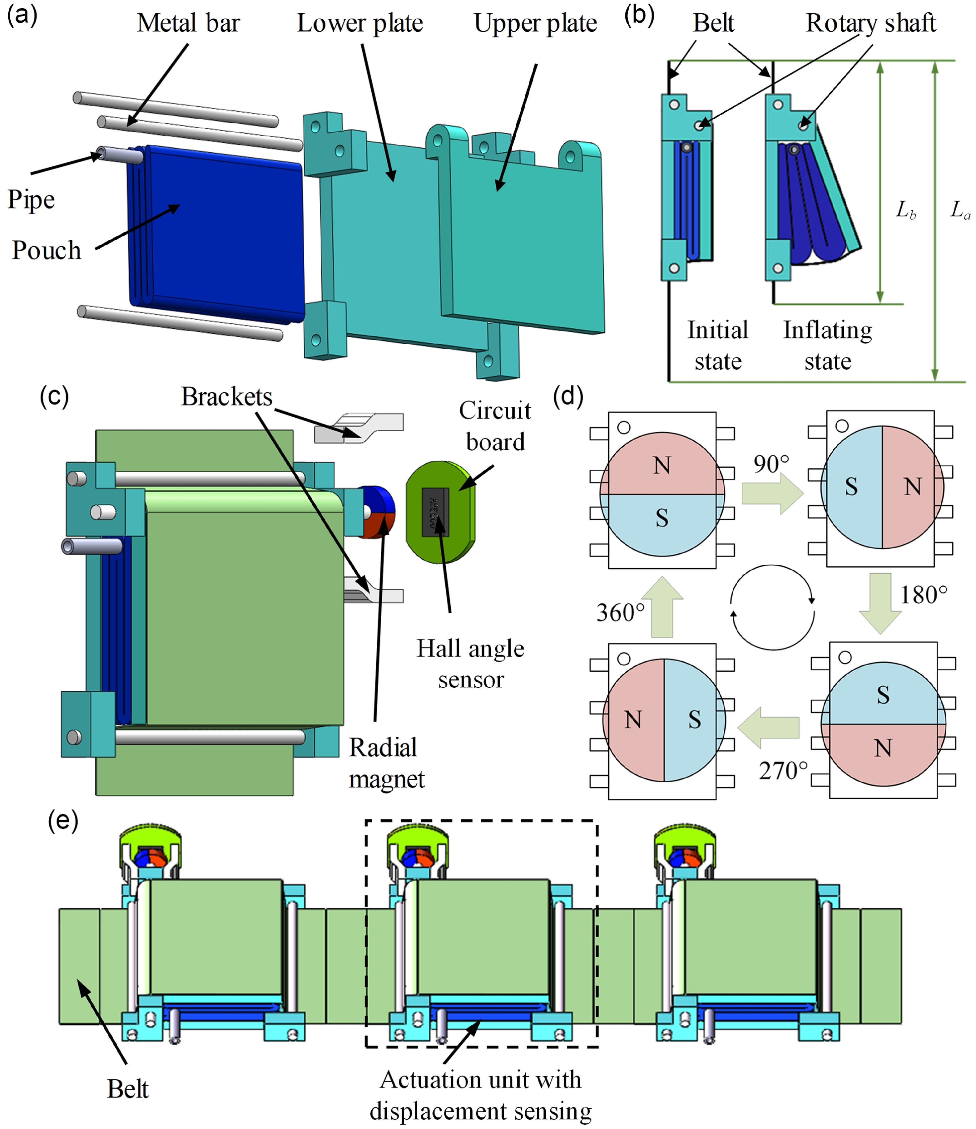
Schematic of the self-contained sensing pouch actuator. (a) Actuation unit components. (b) Actuation unit contraction. (c) Integrated displacement sensing design based on hall sensors. (d) Principle of displacement sensing. (e) 3D model.

In this study, a modified generalized Prandtl-Ishinskii (MGPI) model is established to characterize the hysteresis behavior of the pouch-type actuator. The accuracy of the MGPI model in fitting force–displacement data is verified through experiments conducted on the actuation unit under six different air pressure conditions. Moreover, the model is used in a load compensation system that consists of wearable pouch-type actuators, a pressure control module, and a computer. The main contributions of this study include:
-
(1) A MGPI model for pouch-type actuators. To address the issue of inaccurate force control resulting from the inherent large hysteresis behavior of pouch-type actuators, the MGPI model is developed, combining the aforementioned two approaches. First, the tangent envelope function is determined for the GPI model that maintains a reliable accuracy at high pressures. Second, the MGPI model incorporates asymmetric, non-convex, and memoryless dead-zone operators, so it enhances the capability to accurately fit complex hysteresis curves. Finally, the proposed MGPI model, which employs a reduced number of operators, shows higher accuracy for force control of pouch-type actuators in comparison with modified PI models.
-
(2) A load compensation system for maintaining upper limb posture. First, the MGPI model is used to adjust the output force of self-contained sensing pouch actuators. Second, a relationship between load gravity and the output force of the pouch-type actuator is built. Finally, the load compensation system can be constructed based on the MGPI model and the pouch-type actuator with displacement sensing, thereby reducing reduce muscle fatigue of wearers. Experimental results illustrate that the MGPI model can enhance the control accuracy of output force, which is conducive to maintaining human posture.
2. Hysteresis characteristics of novel pouch-type actuator
2.1. Design of pouch-type actuator
The pouch-type actuator adopts a belt-woven design strategy to enhance modularity. The actuation unit consists of a folded pouch, three metal bars, and two plates, as shown in Fig. 1(a). The folded pouch is placed in the gap between the upper and lower plates. One side of both plates forms a hinge joint through a metal bar. The belt weaves the above whole together, as shown in Fig. 1(b). When the pouch is inflated, the upper plate rotates around the hinge joint, and contraction occurs at both ends of the belt. Contraction displacement of the pouch-type actuator is equal to the difference between L a and L b . The plates can be manufactured with polylactic acid through 3D printing technology, and the belt can be fabricated with nylon fabric (210D, ETHEL, Shenzhen, China). The folded pouch is obtained by heat-sealing nylon fabric thermoplastic polyurethane membrane.
To achieve feedback control of pouch-type actuators, self-contained displacement is necessary. In this section, an integrated displacement sensing sensor is designed based on the hall principle. As shown in Fig. 1(c), the integrated displacement sensor contains a radial magnet, two brackets, and a hall angle sensor (AS5600, QINHEZHINENG, Shenzhen, China). The radial magnet has an 8 mm diameter and a 2 mm height. The brackets are utilized to mount the circuit board on the side of the lower plate. The radial magnet is fixed on the end of a rotary shaft that maintains a certain distance from the hall sensor. The magnetic induction intensity varies with the position of the radial magnet and hall angle sensor, as shown in Fig. 1(d). Consequently, the rotation angle of the upper plate can be measured by the hall sensor. The angle is linearly proportional to the output voltage of the hall sensor. Contraction displacement of the actuator can be calculated according to the rotation angle. The specific calibration process and displacement calculation procedure can be referred to in the previous study [Reference Wang, Ma, Zuo and Liu25]. A pouch-type actuator contains three actuation units equipped with displacement sensors, as shown in Fig. 1(e). The contraction displacement of the actuator can be obtained by these sensors.
2.2. Hysteresis characteristics of actuation units
The factors influencing hysteresis within the actuation unit include system elasticity, friction between the belt and metal bars, and inflation pressure. System elasticity is the primary cause of hysteresis. The elasticity of both the metal bar and belt results in the dissipation of energy as elastic energy during both the contraction and extension phases of the unit, leading to significant hysteresis throughout the entire system.
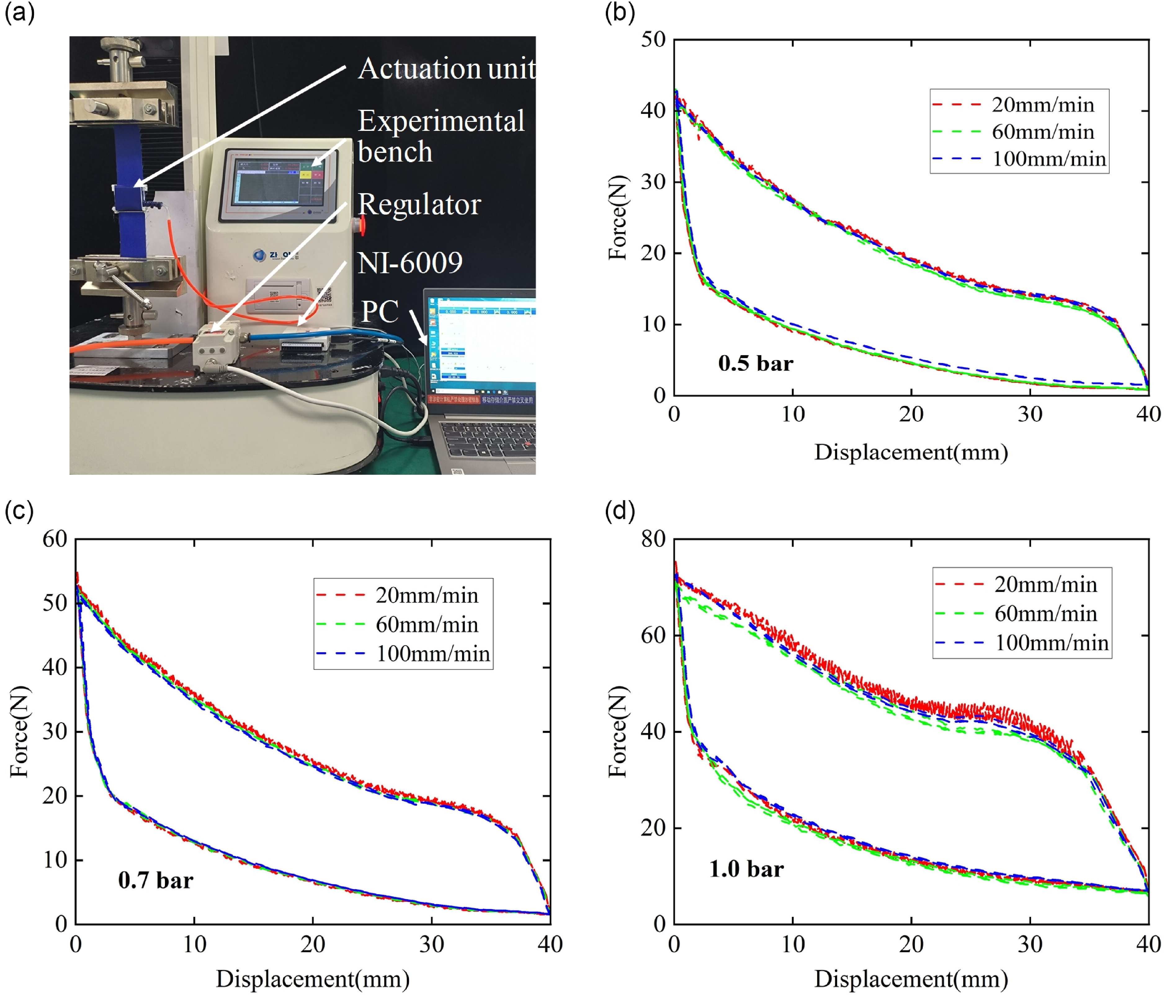
Experiments on the force–displacement hysteresis characteristics of a single actuation unit are conducted, as shown in Fig. 2. Both ends of the actuation unit are mounted on the experimental bench (ZQ-990 LB, ZHIQU, Shenzhen, China). Before the experiments, the bench is adjusted, ensuring that the output force and contraction displacement of the unit are equal to zero. The experimental bench is connected to a computer. And the values of force and position can be transmitted to the computer. A regulator (ITV1020, SMC, Japan) is employed to adjust the air pressure inside the actuation unit. Additionally, the actuation unit performs contraction movements at a constant speed.
Hysteresis experiments under different conditions. (a) Hysteresis experimental bench for actuation unit; Three different experimental conditions: (b) 0.5 bar; (c) 0.7 bar; (d) 1.0 bar.

Before commencing hysteresis testing, it is essential to determine the inflation pressure range and contraction displacement of the actuation unit. Preliminary experiments reveal that inflation pressures below 0.5 bar result in minimal output force and contraction displacement. In contrast, inflation pressures exceeding 1.0 bar and contraction displacements exceeding 20 mm pose a significant risk of damaging the pouch. Therefore, the inflation pressure is restricted to 0.5–1.0 bar. To investigate the influence of testing speed on output force, force–displacement hysteresis characteristics are tested at various speeds (20 mm/min, 60 mm/min, and 100 mm/min) while maintaining constant internal pressure (0.5 bar, 0.7 bar, and 1.0 bar).
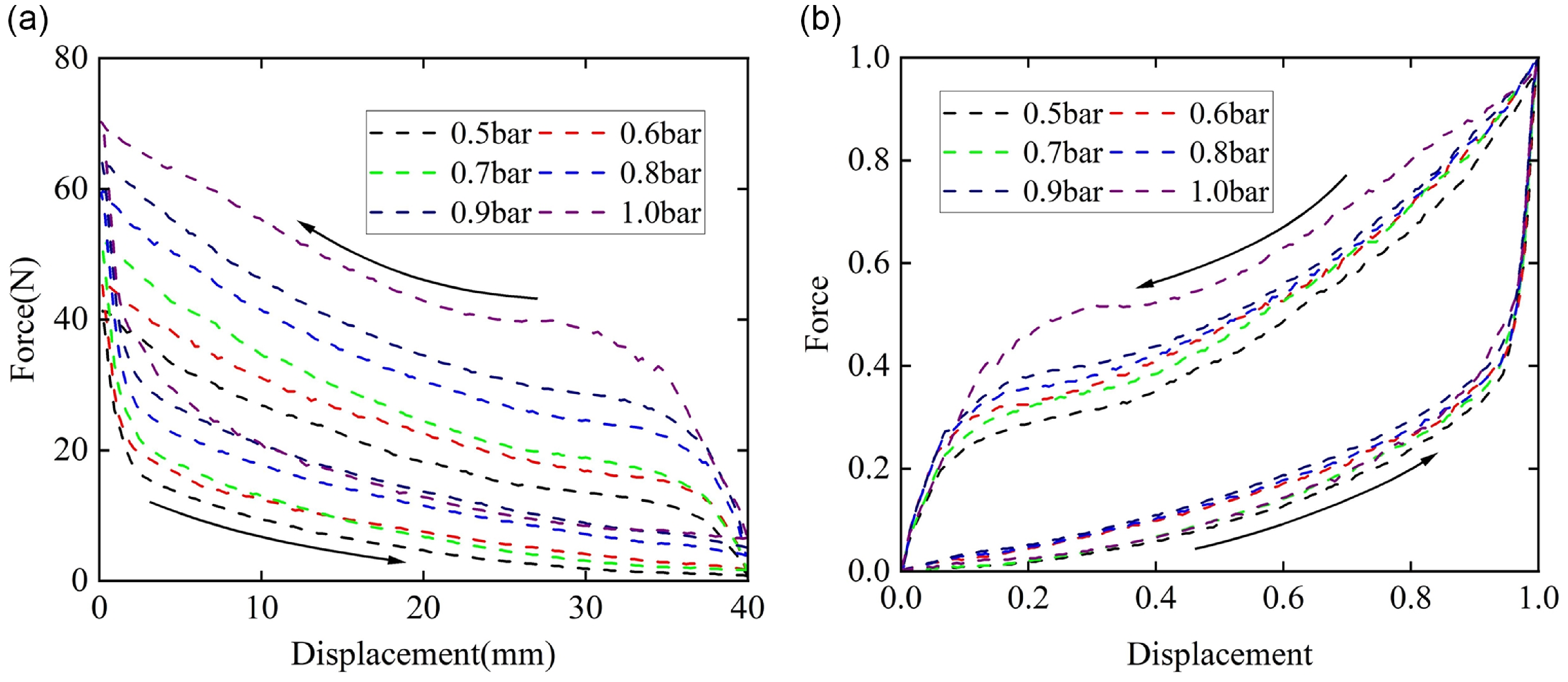
Hysteresis curves between the output force and displacement. (a) Original hysteresis curves; (b) hysteresis curves after coordinate transformation and normalization.

The hysteresis characteristics of the actuation unit are tested with intervals of 0.1 bar, ranging from 0.5 to 1.0 bar. Since testing speed has negligible influence on hysteresis characteristics, the reciprocating speed of the experimental platform is fixed at 60 mm/min, to optimize testing efficiency without compromising sampling adequacy. The relationship between output force and contraction displacement is measured to characterize the hysteresis behavior of the actuation unit, with the results presented in Fig. 3(a). To enhance the characterization of the hysteresis relationship between output force and contraction displacement, the hysteresis curves undergo linear transformation and normalization. The linear transformation and normalization process are as follows:
 \begin{align} x_{new}=-x_{\textit{original}}+40 \\[-25pt] \nonumber \end{align}
 \begin{align} x=\frac{x_{new}-x_{\min }}{x_{\max }-x_{\min }} \end{align}
 \begin{align} F=\frac{F_{\textit{output}}-F_{\min }}{F_{\max }-F_{\min }} \end{align}
where
 $x_{new}$
and
 $x_{\textit{original}}$
are the transformed and original displacement value,
 $x_{\min }$
and
 $x_{\max }$
are the minimum and maximum values of the transformed displacement,
 $F_{\min }$
and
 $F_{\max }$
represent the minimum and maximum output force values, and
 $x$
and
 $F$
represent the normalized values of contraction displacement. Their values are shown in Table I. Since the hysteresis curve rotates clockwise after the previous transformation, the data is reversed in sequence to convert it into a counterclockwise rotation, aligning with the requirements of the subsequent identification model.
The maximum and minimum output force values at each pressure.

Figure 3(b) illustrates a prominent hysteresis phenomenon between the output force of the actuation unit and contraction displacement. Specifically, the force–position characteristics differ between the contraction and extension phases, with asymmetric hysteresis curves observed at every pressure. Additionally, the hysteresis curves at different pressures exhibit distinct shapes, reflecting behavior variations of the actuation unit under varying pressure conditions. The complex nonlinearity and high non-convexity observed in the unit’s hysteresis curve pose significant challenges for classical theoretical modeling methods, resulting in difficulties in achieving accurate descriptions. This paper adopts a phenomenological modeling approach to conduct the entire process and complete the hysteresis modeling of the unit’s force–displacement relationship.
3. Modified GPI hysteresis model
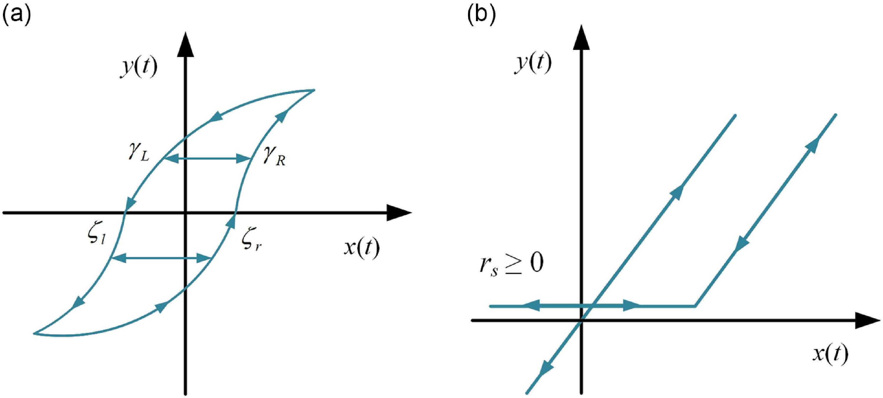
The GPI model, stemming from the PI model, is formulated by integrating a generalized play operator with different weights to feature the hysteresis of smart actuators [Reference Al-Janaideh, Rakheja and Su26]. Its validity is demonstrated by comparing the model responses with distinct types of actuators. The generalized play operator is crucial to construct the GPI model, which can be derived by Janaideh et al. [Reference Al-Janaideh, Rakheja and Su27], as follows:
 \begin{align} y_{r}\left(t\right)=\left\{\begin{array}{l} \max \!\left\{\gamma _{R}\!\left(x\left(t\right)\right)-r,y_{r}\!\left(t-T\right)\right\},x^{\prime}\!\left(t\right)\geq 0\\[3pt] \min \!\left\{\gamma _{L}\!\left(x\left(t\right)\right)+r,y_{r}\!\left(t-T\right)\right\},x^{\prime}\!\left(t\right)\lt 0 \end{array}\right. \end{align}
where
 $\gamma _{R}$
and
 $\gamma _{L}$
belong to the envelope function. The
 $x$
represents the input value and
 $y_{r}$
is the output value. The T represents the sampling period. The t represents the number of sample points. The relationship between the input and output of the generalized play operator is shown in Fig. 4. Additionally, the threshold of the generalized play operator is described by them [Reference Al-Janaideh, Rakheja and Su27], as follows:
(a) Input–output relationship of the generalized play operator; (b) input–output relationship of the one-sided dead-zone operators.

 \begin{align} r=\frac{\gamma _{R}\!\left(\zeta _{r}\right)-\gamma _{L}\!\left(\zeta _{l}\right)}{2} \end{align}
There are mainly three types of envelope functions used in the GPI model for describing hysteresis:
-
(1) exponential envelope function which is employed and validated in the GPI model by Sánchez-Durán et al. [Reference Sánchez-Durán, Oballe-Peinado, Castellanos-Ramos and Vidal-Verdú28], as follows:
 \begin{align} \left\{\begin{array}{l} \gamma _{L}=a_{0}\mathrm{e}^{\left(-{a_{1}}x\left(t\right)+{a_{2}}\right)}+a_{3}\\[3pt] \gamma _{R}=b_{0}\mathrm{e}^{\left(-{b_{1}}x\left(t\right)+{b_{2}}\right)}+b_{3} \end{array}\right. \end{align}
-
(2) hyperbolic tangent envelope function used in the GPI model by Janaideh et al. [Reference Al-Janaideh, Rakheja and Su26], as follows:
 \begin{align} \left\{\begin{array}{l} \gamma _{L}=a_{0}\tanh \!\left(a_{1}x\left(t\right)+a_{2}\right)+a_{3}\\[3pt] \gamma _{R}=b_{0}\tanh \!\left(b_{1}x\left(t\right)+b_{2}\right)+b_{3} \end{array}\right. \end{align}
-
(3) the arc tangent envelope function which is used in the GPI model to improve the modeling accuracy by Xie et al. [Reference Xie, Liu and Wang23], as follows:
 \begin{align} \left\{\begin{array}{l} \gamma _{L}=a_{0}\arctan\! \left(a_{1}x\left(t\right)+a_{2}\right)+a_{3}\\[3pt] \gamma _{R}=b_{0}\arctan \!\left(b_{1}x\left(t\right)+b_{2}\right)+b_{3} \end{array}\right. \end{align}
where
 $a_{i}$
and
 $b_{i}$
(i = 0, 1, 2, 3) are parameters that can be estimated. Thus, the GPI hysteresis model is described by Xie et al. [Reference Xie, Liu and Wang23], as follows:
 \begin{align} y_{r}\!\left(t\right)=\max \!\left\{\gamma _{R}\!\left(x\left(t\right)\right)-r_{i},\min \!\left(\gamma _{L}\!\left(x\left(t\right)\right)+r_{i},y_{r}\!\left(t-T\right)\right)\right\} \\[-24pt] \nonumber \end{align}
 \begin{align} y_{p}\left(t\right)=\sum _{i=1}^{n}p\!\left(r_{i}\right)y_{r}\left(t\right) \end{align}
where n is the number of generalized play operators. Moreover, the weight
 $p(r_{i})$
and threshold value
 $r_{i}$
of the GPI model are given by Xie et al. [Reference Xie, Liu and Wang23], as follows:
 \begin{align} p\!\left(r_{i}\right)=\rho e^{-\tau {r_{i}}} \\[-24pt] \nonumber \end{align}
 \begin{align} r_{i}=\alpha \!\left(i-1\right),i=1,2,\cdots, n \end{align}
where
 $\rho \gt 0, \alpha \gt 0$
and
 $\tau$
are parameters that can be identified.
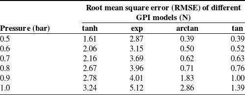
The error values for the GPI model with different envelope functions.

To improve the effectiveness and accuracy of the GPI model, a revised type of envelope function tailored to describe the hysteresis relationship between displacement and output force of the actuation unit is proposed in this study. The tangent function is selected as the envelope function due to its desirable properties of continuity and reversibility, which are essential for accurately capturing the hysteresis relationship. Its expression is as follows:
 \begin{align} \left\{\begin{array}{l} \gamma _{L}=a_{0}\tan \!\left(a_{1}x\left(t\right)+a_{2}\right)+a_{3}\\[3pt] \gamma _{R}=b_{0}\tan \!\left(b_{1}x\left(t\right)+b_{2}\right)+b_{3} \end{array}\right. \end{align}
To achieve parameter identification, the nonlinear least squares method is employed, minimizing the cost function to iteratively adjust model parameters. This method is chosen for its effectiveness in optimizing model fit to experimental data:
 \begin{align} F\!\left(V\right)=\sqrt{\frac{\sum\limits _{i=1}^{n}\left(y_{e}\left(i\right)-y\left(i\right)\right)^{2}}{n}} \end{align}
where the symbol
 $y_{e}$
represents the measured value,
 $y$
represents the estimated value based on the hysteresis model,
 $V=[a_{0},a_{1},a_{2},a_{3},b_{0},b_{1},b_{2},b_{3},\rho, \alpha, \tau ]$
represents the parameters to be estimated, and n is the number of data points. As a nonlinear parameter identification problem, it can be solved with the aid of the barrier function interior point method.
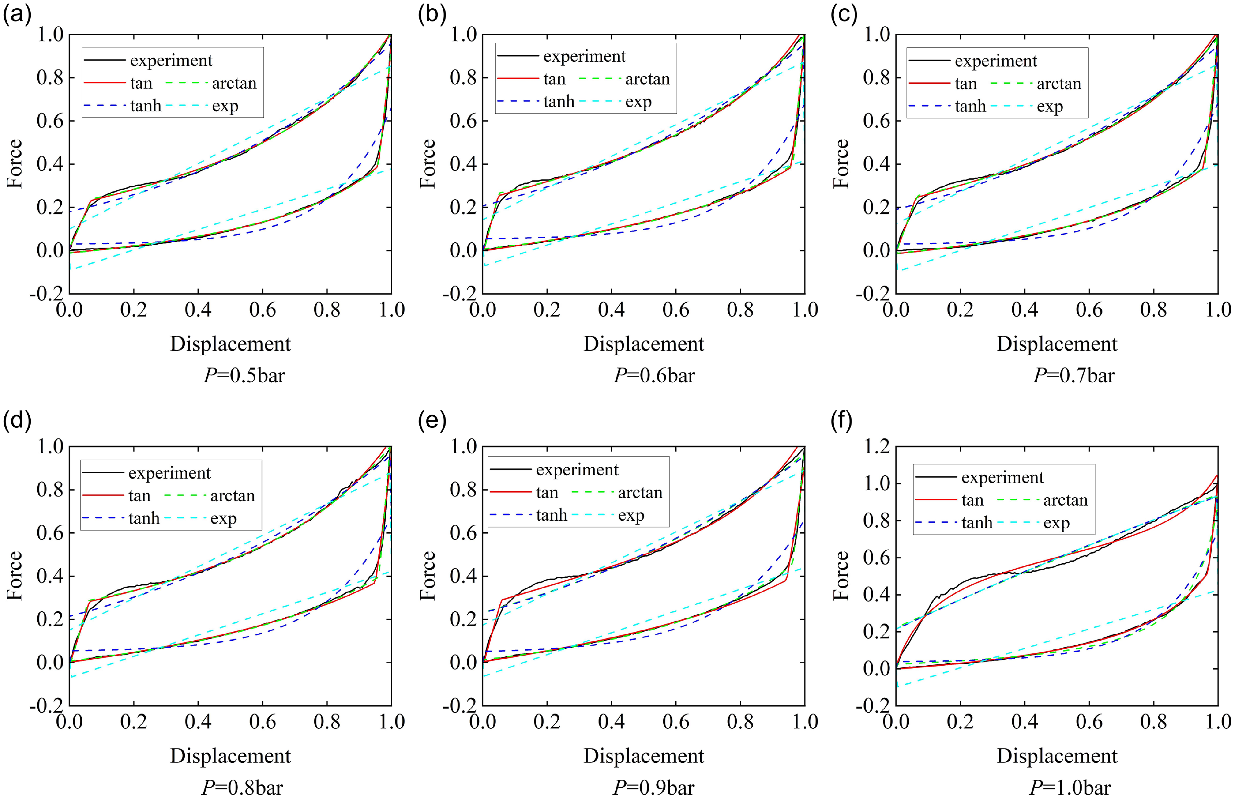
The results are shown in Table II and Fig. 5. By utilizing the aforementioned envelope functions to construct generalized play operators and employing a total of 10 operators, the force–displacement hysteresis under working pressure is identified. This approach aims to capture the complex nonlinearity and asymmetry inherent in the hysteresis relationship. The comparison between measured and predicted values for four models is shown in Fig. 5. Analysis of the results reveals significant errors in the GPI model utilizing tanh and exp envelope functions across all working pressures, indicating their inability to accurately capture this type of hysteresis. While the GPI model with arctangent as the envelope function exhibits good fitting performance at low pressures, its accuracy significantly decreases at high pressures. In contrast to the former three, the GPI model proposed in this study, with the tangent envelope function, demonstrates good fitting performance under all working pressures.
Comparison of different GPI models fitting results and experiments.

The GPI model, utilizing generalized play operators with the tangent envelope function, enhances its capability to fit asymmetric hysteresis while reducing the required number of operators. Nevertheless, when confronted with the complex asymmetric and non-convex hysteresis curves of PAMs, the GPI model continues to exhibit significant inaccuracies. To address these challenges, a MGPI is proposed. The MGPI model incorporates asymmetric, non-convex, and memoryless dead-zone operators, which aim to enhance the model’s capability to accurately fit complex hysteresis curves.
Considering that the force–displacement hysteresis curves of the actuation unit are all in the first quadrant, the dead-zone operator model can be expressed as follows:
 \begin{align} S\!\left(x\left(t\right),r_{s}\right)=\left\{\begin{array}{l} \max \!\left\{x\left(t\right)-r_{s},0\right\},r_{s}\gt 0\\[3pt] x\left(t\right),r_{s}=0 \end{array}\right. \end{align}
where
 $x(t)$
represents the input values of the one-sided dead-zone operators,
 $S$
represents the output values of the one-sided dead-zone operators, and
 $r_{s}$
represents the threshold of the one-sided dead-zone operators.
Similar to the GPI model, the one-sided dead-zone operator model can be expressed as a superposition of operators with different thresholds and weights:
 \begin{align} y_{s}\!\left(t\right)=\boldsymbol{w}_{s}^{T}\cdot \boldsymbol{S}\!\left(x\left(t\right),\boldsymbol{r}_{s}\right) \end{align}
where
 $\boldsymbol{w}_{s}^{T}=[w_{s1},w_{s2},\cdots, w_{sn}]$
is the weight vector of one-sided dead-zone operators,
 $\boldsymbol{r}_{s}=[r_{s1},r_{s2},\cdots, r_{sn}]$
is the threshold vector and satisfies
 $0=r_{s0}\lt r_{s1}\lt \cdots \lt r_{sn}$
, and
 $\boldsymbol{S}\boldsymbol{=}[S_{1},S_{2},\cdots, S_{n}]$
is the output matrix of the dead-zone operators. According to reference [Reference Xie, Liu and Wang23],
 $r_{si}$
can be expressed as follows:
 \begin{align} \left\{\begin{array}{l} r_{s1}=0\\[3pt] r_{si}=\frac{\left(i-1.5\right)}{n-1},i=2,3,\cdots, n \end{array}\right. \end{align}
By combining the generated play operator with the one-sided dead-zone operators, the MGPI model is deduced:
 \begin{align} y\!\left(t\right)=\boldsymbol{w}_{s}^{T}\cdot \boldsymbol{S}\!\left(\sum _{i=1}^{n}p\!\left(r_{i}\right)y_{r}\!\left(t\right),\boldsymbol{r}_{s}\right) \end{align}
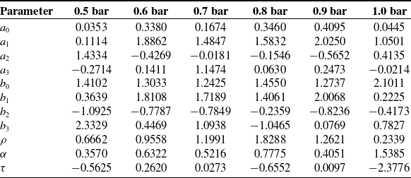
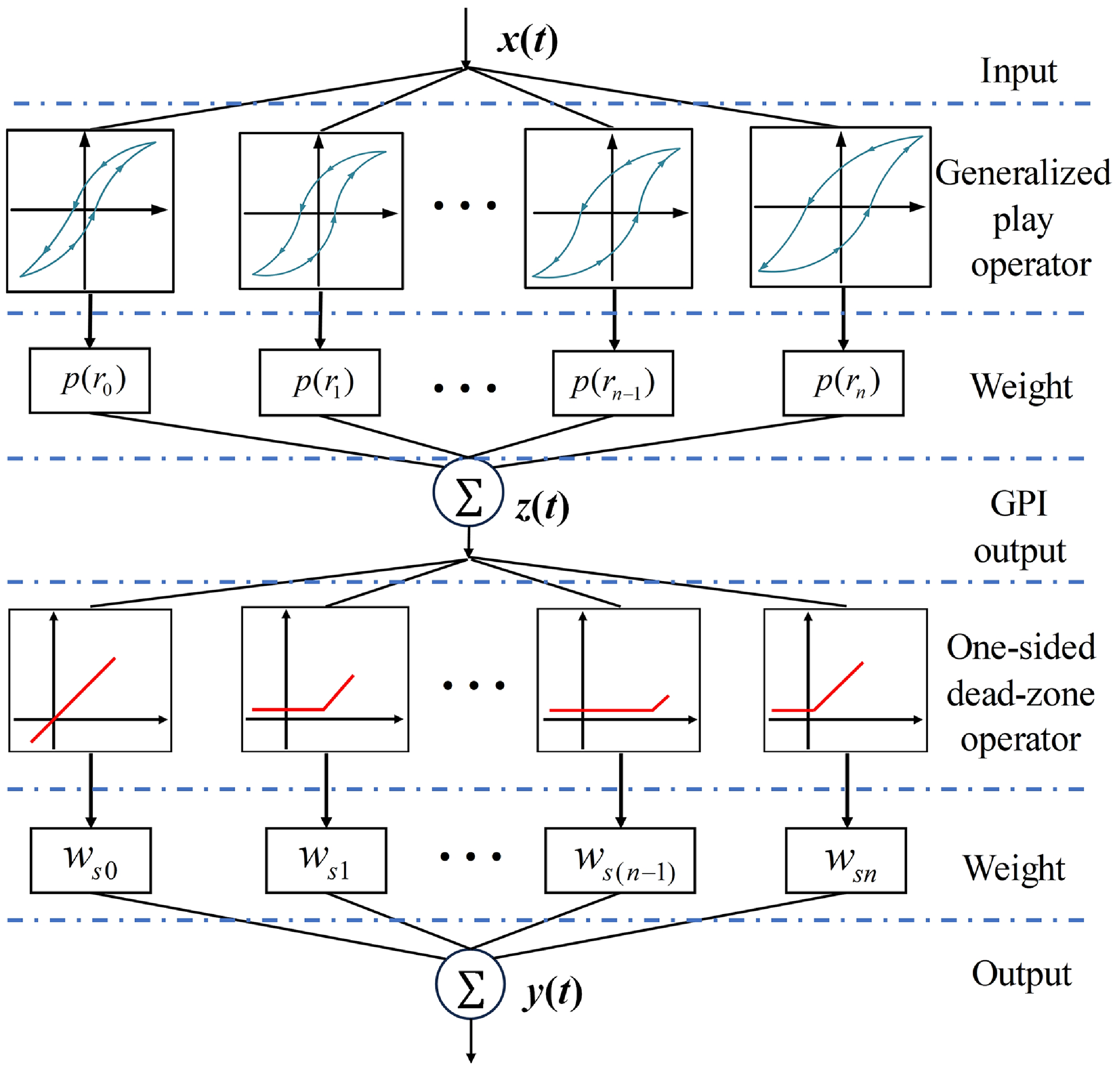
Figure 6 illustrates the principle of the MGPI model, showcasing the integration of generalized play operators with the tangent envelope function and one-sided dead-zone operators. By employing the identification method, the identified parameters of the GPI model with the proposed envelope function are successfully obtained, as shown in Table III.
Identified parameters of the GPI model with the proposed envelope function.

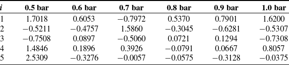
The weights of one-sided dead-zone operators.

Subsequently, the weights of one-sided dead-zone operators are also determined through the parameter identification method, as shown in Table IV. These parameters from the proposed envelope function and the weights of one-sided dead-zone operators were determined across a range of pressures from 0.5 bar to 1.0 bar. They play a crucial role in accurately featuring the hysteresis behavior of the actuation unit.
Principle of modified GPI model.

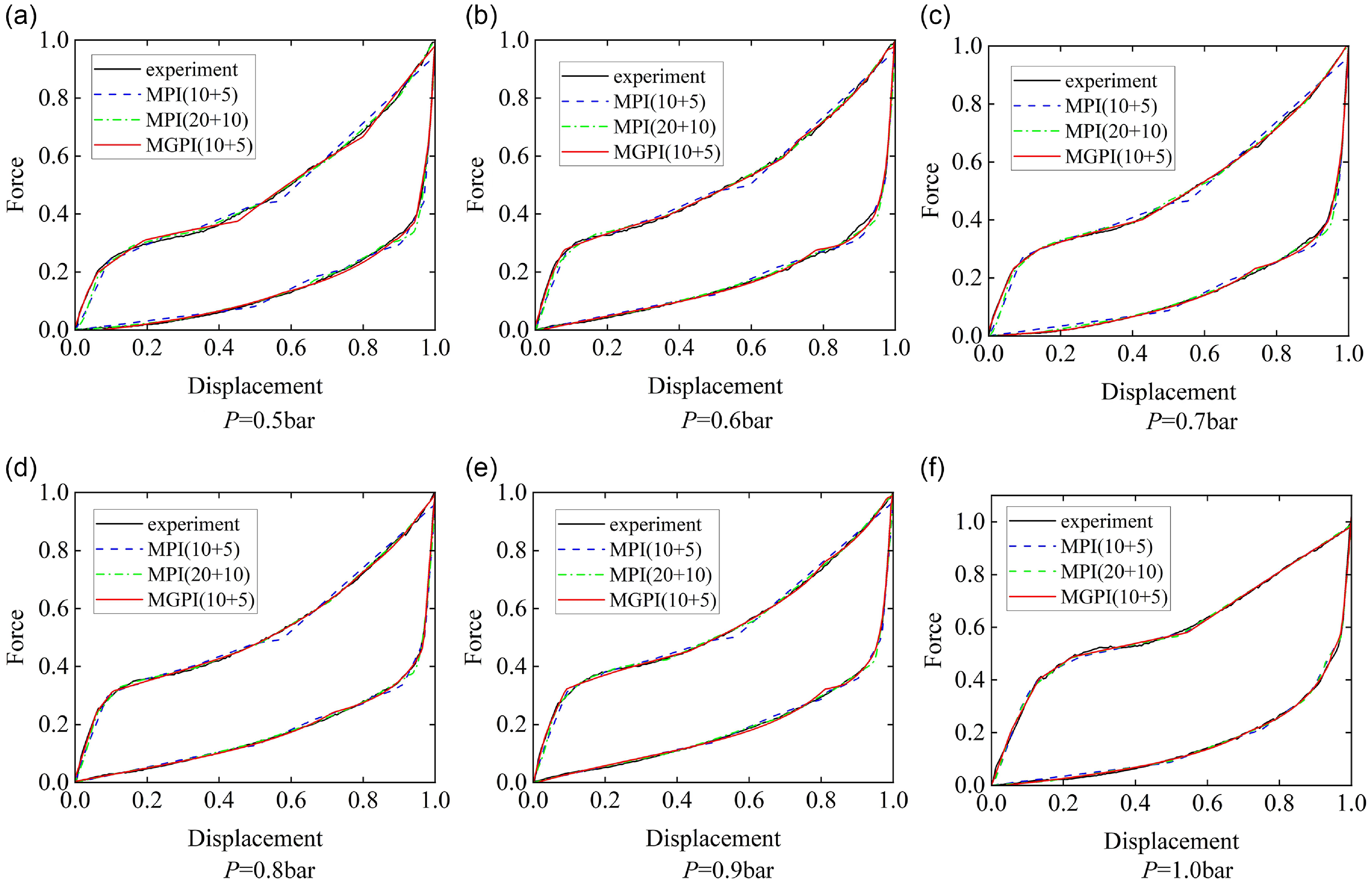
To verify the accuracy of the MGPI model, the experimental data of the actuation unit under different inflation pressures are compared with the fitting results of three models, including the modified PI model consisting of 10 play operators and 5 one-sided dead-zone operators, the modified PI model (MPI) consisting of 20 play operators and 10 one-sided dead-zone operators and the MGPI model consisting of 10 generalized play operators and 5 one-sided dead-zone operators. The results are shown in Fig. 7.
Evaluation of hysteresis models.

Fitting results and experimental results of different models.

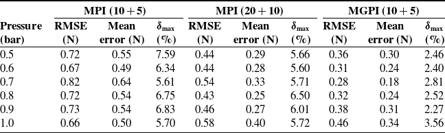
To quantify the effectiveness of the model, this paper selects root mean square error (RMSE), mean error, and maximum relative error as the evaluation criteria. The maximum relative error is defined as follows:
 \begin{align} \delta _{\max }=\frac{\Delta F_{\max }}{F_{\max }} \end{align}
where
 $F_{\max }$
is the maximum output force measured by the experimental setup and
 $\Delta F_{\max }$
is the deviation of the maximum output force.
The proposed MGPI model outperforms both the MPI model, as well as the MPI model, in accurately describing the hysteresis characteristics of the actuation unit. According to the RMSE, mean error, and
 $\delta _{\max }$
values, it is evident that the MGPI model achieves superior fitting accuracy while employing fewer operators, highlighting its efficacy in modeling hysteresis, as shown in Table V.
At each inflation air pressure, the MGPI model demonstrates robust performance, with a maximum relative deviation of 3.56% compared to experimental data at 1.0 bar, indicating its consistency across varying pressure conditions. Furthermore, the MGPI model shows an average error of less than 0.34 N, representing a significant enhancement over the MPI model with equivalent operator conditions. Additionally, the GPI model yields fitting results with RMSE values consistently below 0.46 N, reflecting a notable improvement compared to both MPI models.
In general, compared to the MPI model, the MGPI model can significantly reduce the number of operators and ensure sufficient accuracy by modifying the envelope function when describing complex hysteresis. To feature the asymmetric and non-convex hysteresis curves of various soft actuators, the MGPI model is presented, which can offer a useful method for the hysteresis modeling of pouch-type actuators consisting of many elastic components.
4. Posture maintenance under load compensation test
4.1. Load compensation model
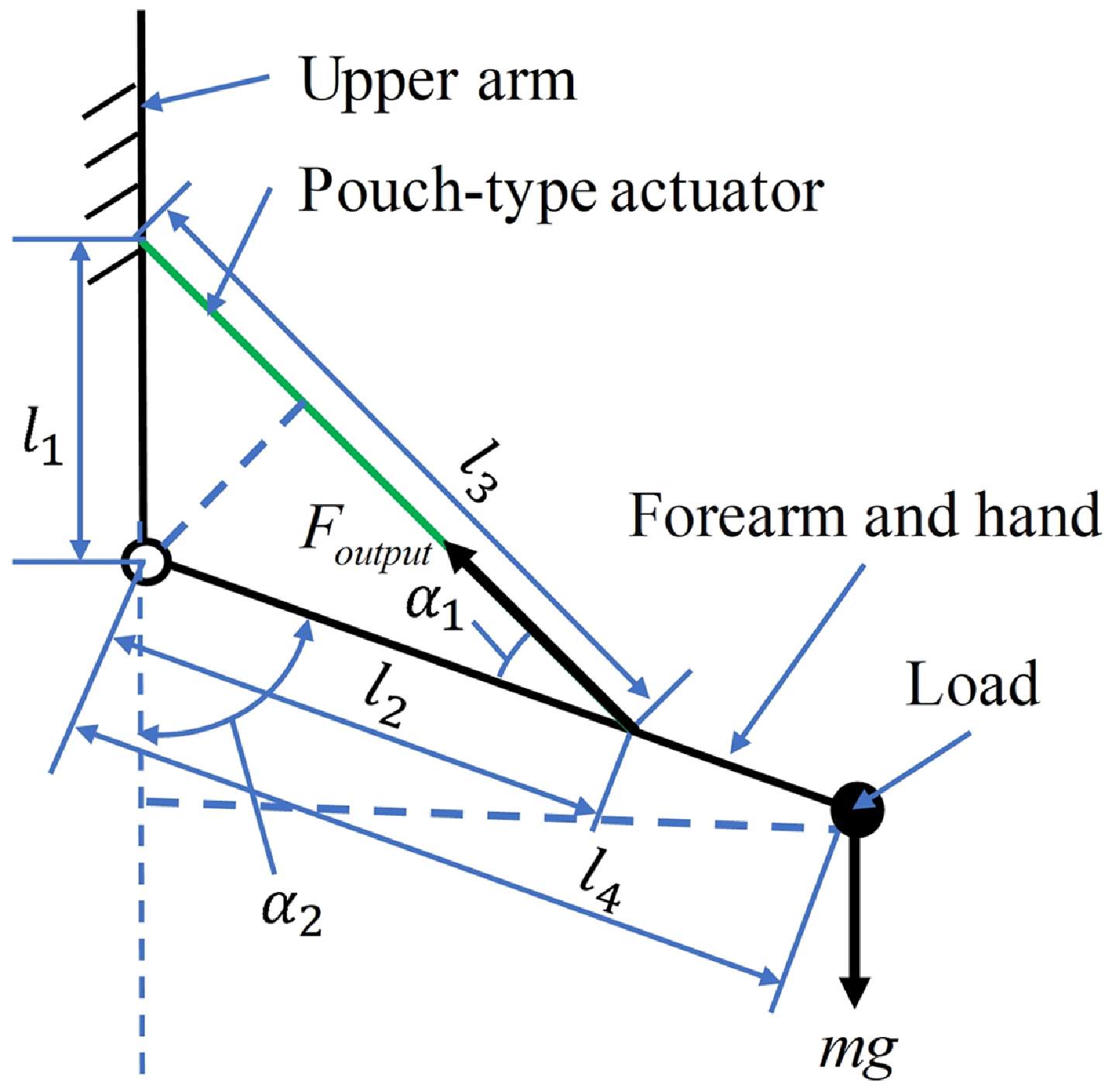
In pursuit of enhanced assistance capabilities with the pouch-type actuator, this section integrates displacement sensing with the hysteresis model to design a load compensation system for upper limb posture maintenance of wearers. This integration can improve accuracy and control in maintaining desired postures. First, a load compensation model is built for a relationship between load gravity and the output force of the pouch-type actuator. As depicted in Fig. 8, it represents a simplified schematic of a subject holding a load and maintaining a certain angle with the assistance of the pouch-type actuator.
The relationship between load weight and output force of pouch-type actuator.

The expressions for angle
 $\alpha _{1}$
between the pouch-type actuator and the forearm and angle
 $\alpha _{2}$
between the forearm and the vertical direction can be obtained as follows:
 \begin{align} \left\{\begin{array}{l} \cos \alpha _{1}=\frac{l_{2}^{2}+l_{3}^{2}-l_{1}^{2}}{2l_{2}l_{3}}\\[3pt] \cos \!\left(\pi -\alpha _{2}\right)=\frac{l_{1}^{2}+l_{2}^{2}-l_{3}^{2}}{2l_{1}l_{2}} \end{array}\right. \end{align}
where
 $l_{1}$
and
 $l_{2}$
are obtained from the specific parameters measured after wearing the actuator and
 $l_{3}$
can be obtained by the difference between the initial length of the actuator and the contraction displacement
 $S_{sum}$
. When the pneumatic muscle is tightly attached to the human arm,
 $l_{3}$
can be represented as follows:
 \begin{align} l_{3}=l_{1}+l_{2}-S_{sum} \end{align}
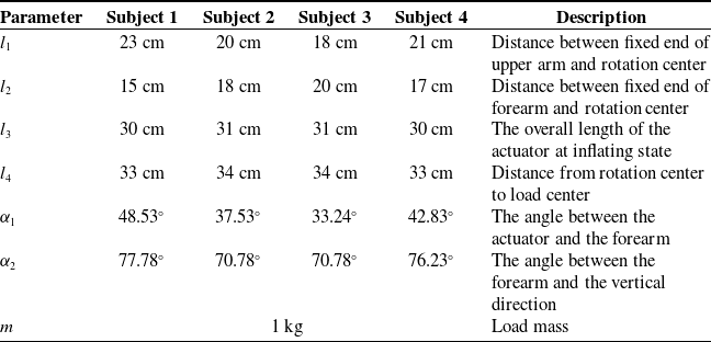
The parameters used for the description of the load compensation system.

Detailed descriptions of these parameters are shown in Table VI. Finally, the relationship between the output force of the pouch-type actuator and the external load gravity can be expressed as follows:
 \begin{align} F=\frac{mgl_{4}\sin \alpha _{2}}{l_{2}\sin \alpha _{1}} \end{align}
4.2. Control strategy
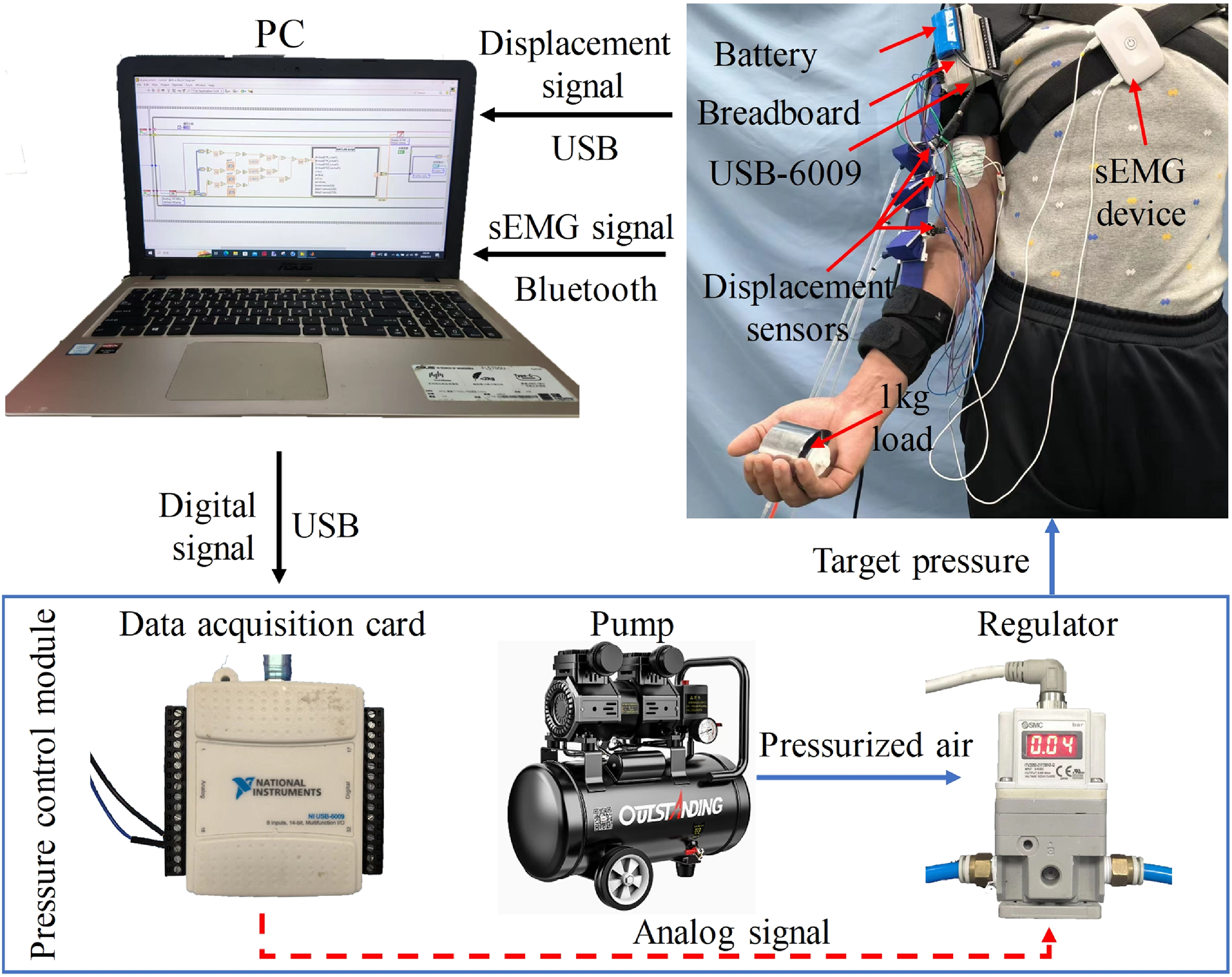
The equipment composition of the human posture maintenance load compensation system is illustrated in Fig. 9. The system primarily consists of three components: the displacement measurement module, the pressure control module, and the computer. The computer is connected to the displacement measurement module (USB-6009 data acquisition card) and the pressure control module via two USB ports to collect output signals from three displacement sensors and control the pressure output. The EMG acquisition card (Biosignalsplux, Plux Wireless Biosignals S.A., Portugal) connects to the computer via Bluetooth to collect surface EMG signals of subjects during the experimental process.
Load compensation system for posture maintenance process.

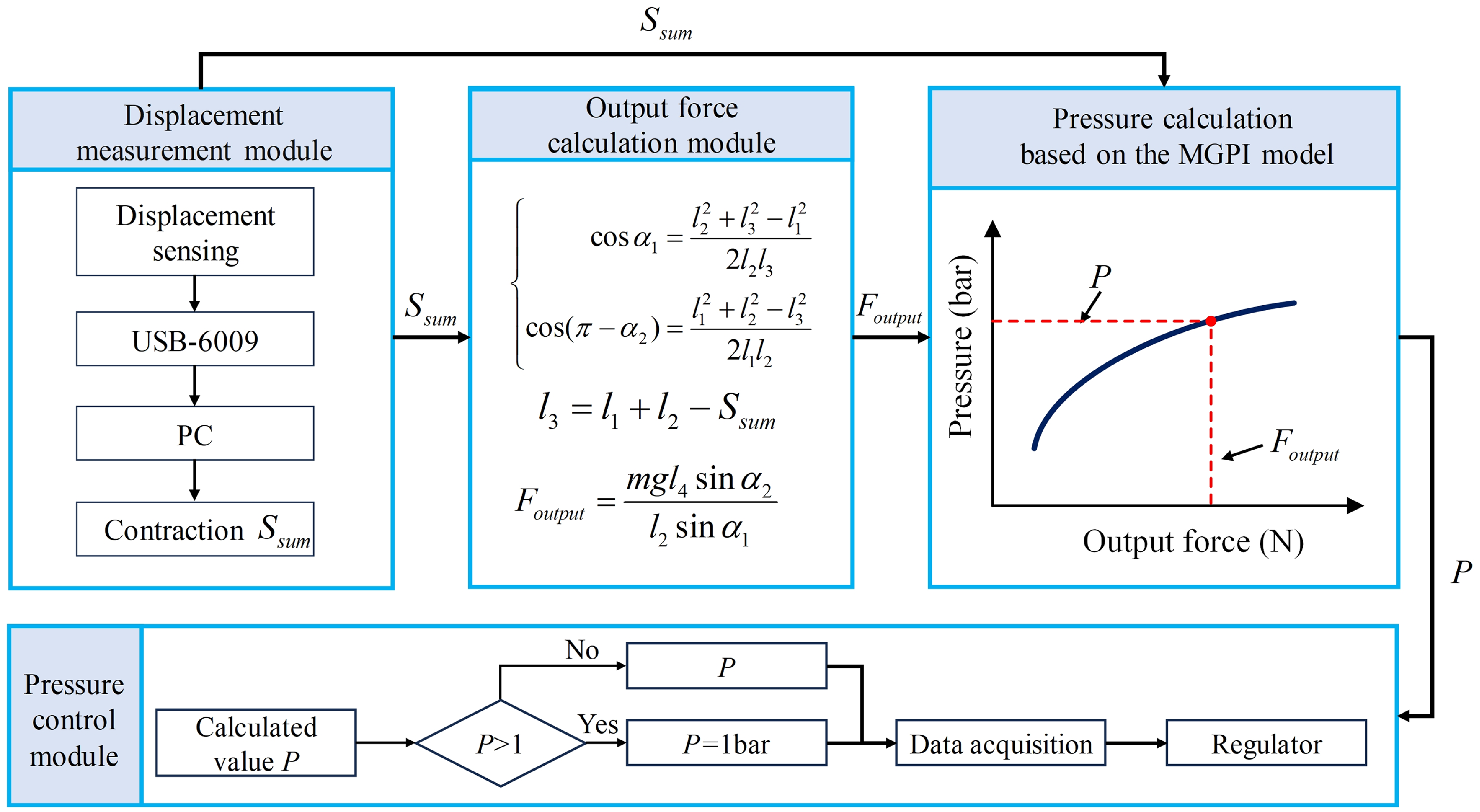
The control principle of the load compensation system is illustrated in Fig. 10. The displacement sensor output signals from the actuation unit are collected, and the contraction displacement of the actuator is computed on the computer. This displacement
 $S_{sum}$
is then used in the output force calculation module to determine the required output force
 $F_{\textit{output}}$
. Since the actuator consists of three actuation units by the series method. The displacement and the output force are inputted into the pressure calculation module to calculate the theoretical air pressure P based on the MGPI model during the extension phase. This pressure value is passed to the air pressure control module, which determines whether it exceeds 1 bar. If it exceeds 1 bar, the computer controls the regulator to output air pressure of 1 bar; otherwise, it outputs the calculated pressure value P.
Load compensation control strategy during posture maintenance.

4.3. Wearing test
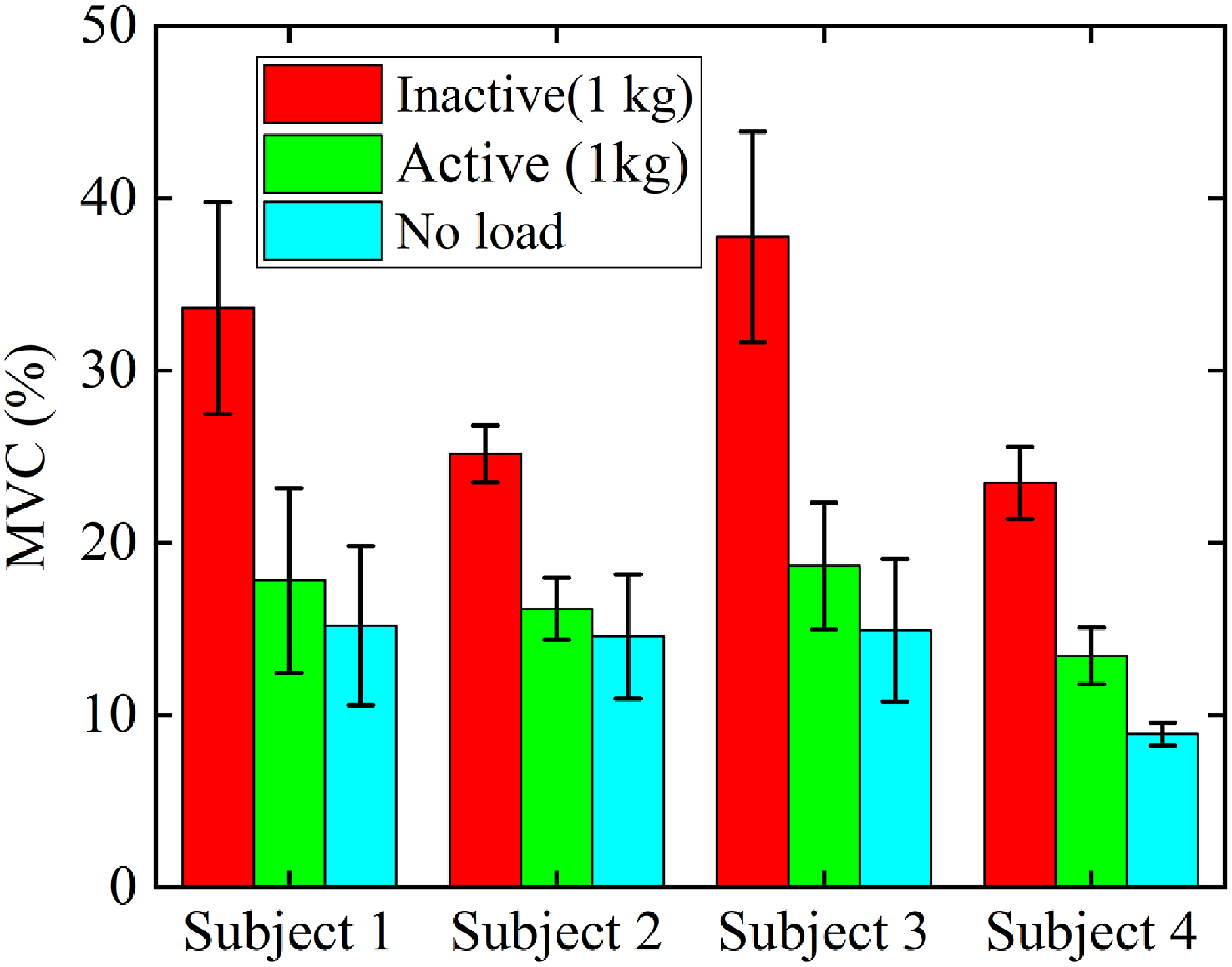
This section involves four subjects in wearing tests under a 1 kg load condition, measuring the surface electromyographic (sEMG) signal intensity of each subject in trials for 10 s: 1 kg load without assistance, 1 kg load with assistance, and posture maintenance without load. The sEMG signal of the bicipital muscle can be collected by the device with a sample rate of 1000 Hz. Using a 4th-order 10–300 Hz bandpass filter to process the sEMG signal, the envelope of the sEMG signal can be obtained through a 4th-order 10 Hz low-pass filter. Then it is averaged over a time window of 500 ms, during which the sEMG signal intensity is stable and normalized by the maximum voluntary contraction (MVC). Final test results are shown in Fig. 11. The results indicate that among all subjects maintaining posture when carrying a 1 kg load, the average activation intensity of muscles is significantly reduced when using pneumatic muscle assistance compared to no assistance. This suggests that pneumatic muscles have a significant effect in offsetting the gravity of the load.
The wearing test results of posture maintenance load compensation.

To quantify the load compensation performance, this study uses the electromyographic average activation intensity during posture maintenance without load as a reference point and defines the pneumatic muscle load compensation efficiency
 $\eta$
with the following expression:
 \begin{align} \eta =\left(\frac{\left(Z_{1}-Z_{3}\right)-\left(Z_{2}-Z_{3}\right)}{Z_{1}-Z_{3}}\right)\times 100\% \end{align}
where
 $Z_{1}$
represents the average muscle activation intensity under a 1 kg load without assistance,
 $Z_{2}$
represents the average muscle activation intensity under a 1 kg load with assistance, and
 $Z_{3}$
represents the average muscle activation intensity during posture maintenance without any load.
Based on (23), the load compensation efficiencies of the four subjects can be calculated to be 85.84%, 84.92%, 83.63%, and 68.86%, demonstrating the ability to achieve significant offsetting, thus proving the effectiveness of the approach. Although the control model calculations indicate that a 100% offset of the load gravity can be achieved, the result is still deemed acceptable considering the impact of factors such as the decrease in output force due to elastic deformation of the flexible straps.
5. Discussion and conclusion
A self-contained sensing pouch actuator is designed. The hysteresis of the actuator is analyzed, and the hysteresis curves under different inflation pressures are obtained by experiments. By combining the generalized play operators with the tangent envelope function and one-sided dead-zone operators, an MGPI model for describing the asymmetric and non-convex hysteresis of pouch-type actuators is proposed. Comparative analysis reveals that the GPI model with the tangent envelope function outperforms other envelope functions across various pressures, demonstrating superior fitting efficacy and reduced generalized play operator count. The introduction of dead-zone operators further enhances the capability of the model to describe asymmetric and non-convex hysteresis curves. Compared to the classical PI model with dead-zone operators, results indicate that under the same operator count, the MGPI model exhibits lower mean errors and relative errors at different air pressures. Comparing the identification results of the MPI model with 20 play operators and 10 one-sided dead-zone operators, it is observed that although the MPI model exhibits lower average errors at some pressures, the MGPI model still outperforms the MPI model in terms of RMSE and relative errors. This demonstrates that the MGPI model can achieve accurate hysteresis characterization using fewer operator counts. Finally, integrating the hysteresis model with displacement sensing, a human posture maintenance load compensation system is developed. Four subjects are recruited to undergo human subject testing under a 1 kg load condition. The sEMG signal testing results show that load compensation efficiencies of 85.84%, 84.92%, 83.63%, and 68.86% for the four subjects can be achieved, indicating the excellent applicability of the model.
The hysteresis model proposed in this paper is independent at different air pressures. In future work, the air pressure values will be incorporated into the generalized play operator to improve the threshold expression. This will enable a unified representation of the force–displacement hysteresis model for the actuation unit at various air pressures. Additionally, efforts will be made to enhance predictive accuracy by further refining the hysteresis model algorithm and incorporating the elastic deformation analysis of the flexible straps into the model to further improve load compensation efficiency.
Author contribution
Zhuo Ma, Yingxue Wang, and Jianbin Liu conceived and designed the study. Zhuo Ma and Yingxue Wang conducted data gathering. Rencheng Zheng, and Haitao Liu reviewed the article thoroughly. Zhuo Ma, Yingxue Wang, and Jianbin Liu wrote the article.
Financial support
This work was supported by National Natural Science Foundation of China under Grant No. 52475067
Competing interests
The authors declare no competing interests exist.
Ethical approval
This work involved human subjects. Approval of all ethical and experimental procedures and protocols was granted by the Institutional Review Board of School of Mechanical Engineering, Tianjin University.