Nomenclature
- Al
-
Aluminum
- PU
-
Polyurethene
- SRS
-
Shock Response Spectrum
- SS
-
Stainless Steel
1.0 Introduction
Many spacecraft employ a multi-stage configuration to enhance the mass ratio of the space vehicle, leading to improved rocket performance and higher velocities than single-stage systems. The fundamental objective of the stage separation system is to ensure the swift, clean and flawless separation of rocket stages at specific time intervals. It is paramount for stage separation systems to facilitate the safe and reliable detachment of two rocket stages after the cessation of thrust from the lower stage. The technical intricacy of the stage separation mechanism is pivotal to the successful flight of a multi-stage rocket system. Even single-stage missiles with separating warheads necessitate a separation mechanism.
Pyrotechnic-based separation mechanisms have been widely utilised to effectuate the separation of rocket stages as well as other structural systems. The command for stage separation is issued to jettison the expended stage when the propellant in the rocket motor is nearly depleted. A triggering electrical signal activates detonators, which in turn initiate separation mechanisms like explosive bolts or linear explosive charges to sever the structural connection between the stages. The actuation of these pyrotechnic and explosive mechanisms results in the generation of intense shock waves characterised by high amplitude and short duration (<1ms). Owing to the innate high-frequency nature of pyro shock, numerous fragile elements and electronic devices, including ceramics, circuit boards, valves, relay switches, glass envelopes, solder joints and wire leads, are notably susceptible to pyrotechnic shock failure.
Data from C.J. Moening [1, Reference Moening2] documented that up to 1984, approximately 600 launches experienced 83 shock-related failures. Over 50% of these failures culminated in catastrophic mission failures. Within these instances, ‘30’ involved broken wires and leads, as well as cracked glass; ‘29’ entailed dislodgment of contaminants; ‘20’ exhibited other shock/vibration-related effects, and ‘4’ resulted in relay chatter and transfer problems, leading to the loss of booster and payload. Furthermore, it was also reported that 25% of all launch vehicle failures in the U.S. between 1983 and 1998 were attributed to separation systems [Reference Isakowitz, Hopkins and Hopkins3], with staging-induced pyro shock loads representing a prevalent cause of separation system failures.
2.0 Pyro shock environment
The pyro-shock environment is extremely complex, making it challenging to develop an accurate mathematical model. Existing open literature provides limited information about the fundamental mechanism of shock transmission and prediction of shock response. The specific nature of pyro shocks, characterised by their complexity and high frequency, has hindered the attainment of a mature level of accurate pyro shock prediction, design and test verification when compared to other engineering disciplines.
Understanding the attenuation of pyro shock transients is crucial for designing effective separation mechanisms. The attenuation of pyro shock events is influenced by various factors, including shock magnitude, material of construction, shock load path distance, structural geometry discontinuities and types of joints in the shock load path. Guidelines from NASA and MIL handbooks and standards [4], which were formulated based on extensive tests from the 1960s, offer estimations for the attenuating effects of distance, joints and other structural features in the load path between the shock source and the shock-sensitive component.
The pyroshock environment is generally categorised into near-field, mid-field and far-field regions based on the shock pattern characteristics. To assess the functionality of sensitive components in the shock environment, extensive experiments are necessary. These experiments can simulate pyro shock incidents using optical, mechanical or pyrotechnic methods. The separation phenomenon can be accurately represented by simulating the event with actual pyrotechnic devices.
Numerous techniques have been proposed to attenuate pyroshock during propagation through structures. Babuska et al. [Reference Babuska, Gomez, Smith and Hammetter5] have suggested shock attenuation with distance, introducing different types of joints in the shock propagation path, and designing shock-sensitive equipment joints using proper FEA tools. Modern researchers and designers often rely on FEM tools to design pyro shock joints. Dae-Oen Lee et al. [Reference Lee, Han, Jang, Woo and Kim6] have proposed various pyroshock prediction methods during launch vehicle separation. Despite the usefulness of these prediction tools in initial design phases, most components still require extensive experimentation for safe qualification.
The complex nature of pyroshock encountered during stage separation events presents challenges to the designers. To enhance the design of stage separation mechanisms, system-level tests are conducted on shock-sensitive components to simulate real separation events. Avionic components vulnerable to pyroshock are isolated from the shock source by mounting them on shock isolators or relocating them to low shock regions. Additionally, ordinance systems are redesigned to reduce shock levels [Reference Graham7]. These design methodologies have resulted in the development of various stage separation mechanisms. B.N. Suresh and K. Sivan [Reference Suresh and Sivan8] have described different stage separation mechanisms used worldwide in current launchers. One widely used mechanism is the split collet release or pyrobolt mechanism, which has transitioned from a linear cord-based separation system to a multi-point separation system. This mechanism involves using a plurality of pyro-induced separation bolts or pyrobolts that release the spent stage or payload on command. The benefits of pyrobolt-based mechanisms include ease of assembly, high reliability, low separation disturbances and containment of debris. Y.N. Srinivas Rao et al. [Reference Naga Sreenivasa Rao, Prakash, Subramanian, Purushothaman, Premdas, Abraham, Kishorenath and Jayachandran9] provide a detailed description of the split collet-based separation system or pyrobolt system used in separating the spent booster stage for the Hypersonic Technology Demonstrator Vehicle (HSTDV). This compact design boasts a high load-bearing capacity. For the current study, experiments have been conducted using actual pyro cartridges on pyro bolts and pyro pin puller mechanisms.
3.0 Details of different shock attenuation methods
A significant body of research and development efforts has been directed towards mitigating pyroshock at various levels. Multiple attenuation techniques have been explored, including the use of energy-absorbing devices and shock load path isolation. For instance, shape memory alloy has been investigated for its capacity to absorb and dissipate pyroshock energy due to its pseudo elasticity [Reference Youn10]. Moreover, studies have demonstrated promising characteristics of the metal rubber damper for space applications [Reference Ming, Qianguang, Liqiang and Xinbo11]. Enhancing discontinuities in the intervening structure has been identified as a method for isolating pyroshock energy [Reference Winfree and Hyunchul Kang12]. Further details of pyroshock attenuation techniques can be found in works by Zhang Huan [Reference Huan, Tianxiong, Shuhong, Changjiang and Qingming13]. Notably, Hyun-Su Park [Reference Park, Hwang, Han and Yang14] has successfully showcased an improved shock attenuation achieved through a novel sandwich insert design compared to traditional shock isolators.
Juho Lee et al. [Reference Lee, Hwang and Han15] have proposed various methods for pyroshock attenuation, including the deployment of materials with different densities and stiffness in joints. Additionally, Wenliang Gao [Reference Gao, Qin and Chu16] has introduced a novel method for shock attenuation during pyroshock propagation through the structure by utilising periodic composite rods made of different materials. However, most of these studies have concentrated on the far-field region and attenuating pyroshock along the shock load path, rather than directly reducing shock initiated by pyro-actuated devices. It is worth noting that these studies mainly utilised mechanical devices for simulating pyroshock. Efforts have been made to minimise shock levels by transitioning to non-pyrotechnic initiation systems, resulting in even lower shock values [Reference Laughlin17]. Furthermore, significant progress has been achieved in developing pneumatic-based stage separation systems, such as the innovative Metering Adiabatic Gas Struts for Ares I flight [Reference Floyd and Owens18]. While these systems effectively decrease shock levels, they do incur a weight penalty for upper-stage systems. Additionally, various low-shock separation devices have been proposed [Reference Floyd19], but their design often leads to increased weight. Amitabh et.al [Reference Chakraborty, Rathi, Srinivasan, Khalane, Ramakrishna and Murthy20] have conducted a study to address this challenge by developing a low-weight gas generator-based separation system with shock levels significantly lower than conventional pyro-based devices.
3.1 Design of experiments
After a comprehensive review of prior works on pyro-shock reduction, it has been determined that pyro-shock attenuation in pyro-actuated devices can be achieved through the following methods:
-
(a) Attenuation through the use of shock absorbers and dampers
-
(b) Attenuation via shock load path isolation
-
(c) Attenuation at the shock source
The present study focuses on reducing shock in the near-to-mid-field region. Based on these considerations, the present work conducted experiments divided into three stages, primarily focusing on two types of pyro-actuated separation devices. In the initial stage of experiments, different shock-absorbing configurations were studied to attenuate shock using absorbers and dampers. The second set of experiments involved attenuation through complete load path isolation, by removing various components in contact with each other during pyro firing. This aimed to achieve total isolation of the shock generated from pyro cartridges to the associated structural components. The final series of tests involved shock attenuation by transitioning from pyro-based explosive initiation to a pneumatic initiation method, with shock levels being recorded.
The experiments conducted represent a unique and novel set of methodologies that, to the author’s knowledge, have not been previously employed in other studies. Specifically focusing on pyro-actuated devices, which have demonstrated reliability in numerous flight trials, these experiments were performed on two pyrotechnic devices, namely, the pyro-actuated pin puller and the pyro-actuated separation bolt. The details of the pin-puller and separation bolt are elaborated in the NASA technical document [Reference Seeholzer, Smith, Eastwood and Steffes21]. All these experiments utilise a highly responsive piezo-electric shock sensor to capture the devices’ high-frequency responses. All testing hardware was developed in-house and the test setup has been extensively validated for conducting shock survivability tests of various avionic systems. The primary aim of this research is to mitigate shock levels to thresholds that are tolerable for most avionic components.
Importantly, the observed shock levels recorded by pyro-actuated devices during actual tests manifest high variability and display highly dispersed values that are not repetitive. Therefore, for the present study, the reduction of pyro shock is only considered if there is a noticeable (an order) reduction in shock magnitude. Furthermore, all three categories of experiments were conducted using the same test setup and shock sensors to ensure the consistency of experimental results. The study employed shock sensors mounted in the near-field and mid-field region of the pyro shock source to accurately capture the shock reduction phenomenon.
4.0 Experiments on attenuation by use of shock absorbers and dampers
These experiments were conducted using both pin puller and pyro bolt separation devices. A shock absorber is a component that serves to reduce or mitigate the pyro shock. The various shock absorbers used in the present study are polyurethane foam, aluminum foam, a stainless steel honeycomb structure and an aluminum conical catcher. These absorbers were assembled to pin puller configuration only. A damper is a device that reduces the amplitude of the shock acceleration thereby attenuating its effect. The dampers were used in pyro bolt assembly only. The different dampers considered for the experiments are silicone grease encapsulated pipe, clay and silicone putty.
Typical pin puller configuration.

4.1 Experiments with shock absorbers-pin puller device
The pin puller mechanism is a crucial part of the locking mechanism for various aerospace components, such as fins, bands, nozzles, nose cones and heat shields. It is designed to secure these components during transportation and initial flight loads. The mechanism consists of a body housing a pyro cartridge and a moving pin or piston that is initially locked by a shear pin. When the pyro cartridge is fired, the pressure inside the body and piston head shears the pin, allowing the piston to move and free the bandages. A shock attenuator is used to catch the piston, dissipating its high-impact energy and reducing the pyro shock energy. The details of the working principle of different types of pin puller configurations are given in NASA documents [Reference Seeholzer, Smith, Eastwood and Steffes21] and pyro shock seminars [Reference Chang22]. The details of the pin puller mechanism are shown in Fig. 1. Tests were conducted both with and without shock absorbers to compare shock attenuation and assess the structural integrity of the hardware.
Various types of shock attenuation devices were tested, including aluminum foam, polyurethane (PU) foam, metallic honeycomb structures and an aluminum catcher with a conical interference. These materials exhibit good resistance to shock and vibration. The details of the shock absorbers are given in the following sections.
4.1.1 Foam made of aluminum material
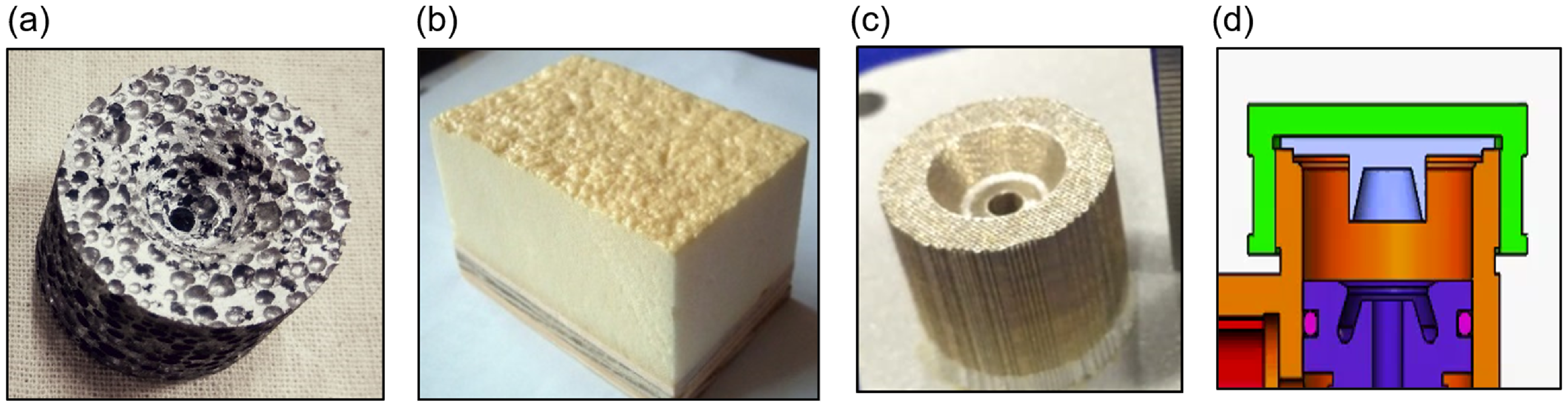
Aluminum foam (as shown in Fig. 2(a)) products of uniform density (from 0.3 to 0.8g/cm3) are made by a simple foundry-based batch process involving aluminum melting. These structures have been reported to be highly effective in mitigating the shock generated due to projectiles in blast applications. For the present study, two types of aluminum foam were used, one with high density (0.8g/cc) and the other with low density (0.4g/cc).
4.1.2 Polyurethane (PU) foam
Polyurethane (PU) foam (as shown in Fig. 2(b)) is a light-density material with a very high level of porosity (about 90%). It consists of fine pores and ideal material for shock absorption application. This material was also selected for the present study as it is extremely soft and crushable. In many case studies, it has been found that the PU foam has exhibited good attenuation properties.
4.1.3 Metallic honey comb structure
Honeycomb structure is an ideal material used for shock-absorbing applications. These honeycomb structures consist of a very fine pore size (less than 0.5mm) and are manufactured using 3D printing technology. Similar materials have been extensively used as safety components to inhibit injuries/damage sustained during car crash accidents. For the study, both coarse pore size (0.8mm) and fine pore size (0.4mm) metallic honeycomb structures were used (refer to Fig. 2(c)).
4.1.4 Aluminium catcher with conical interference
The catcher has a conical taper so that the pin puller gets jammed into the catcher and absorbs the shock generated. The amount of energy absorbed in deforming the material aids in attenuating shock energy. This mechanism helps the material to be arrested at the top and gets locked in position at the end of the stroke (as shown in Fig. 2(d)).
Different dampers used for test. (a) Aluminum Foam (b) Polyurethane foam (c) Steel Honeycomb (d) Aluminum catcher with conical interface.

4.1.5 Test setup, instrumentation plan and details of shock sensor used
Test set-up:
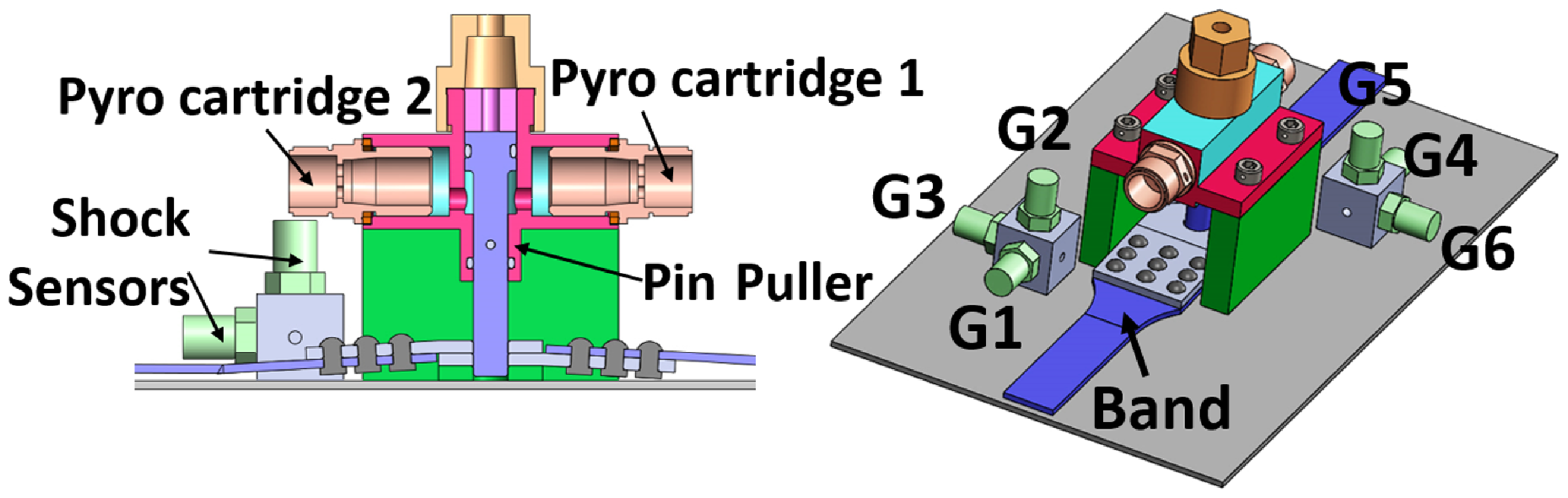
The test article consists of a pin puller mechanism actuated with two numbers of pyro cartridges on either side. The test article was designed and manufactured in-house. Though the working principle of the pin puller remains the same as given in the NASA technical documents, the internal configuration was designed as per a specific application, which is to hold an aerospace structure during transportation and deploy during flight. On actuation of the pin puller, the band holding the component is free to separate. The pin puller hardware was placed on a rigid platform. The platform is a steel structure, which was bolted to the ground. The test rig is designed in-house exclusively for pyro-actuated mechanism testing and validated in many shock tests. The model of the pin puller hardware is shown in Fig. 3. The test article held on a rigid platform is shown in Fig. 4.
Details of test instruments (shock sensor)

Model of test hardware & testing scheme.

Pin puller test hardware on test stand.

Sensor details:
Shock measurement was carried out with uni-axial shock sensors mounted in three directions: axial, vertical and lateral. These measurements were taken at two locations on either side of the pin puller at 80 and 100mm from the pyro cartridges. G1-G3 corresponds to shock sensors mounted in Location 1 (100mm) and G4-G6 shock sensors correspond to Location 2 (80mm), respectively (as shown in Fig. 2). Initially, the shock range was set at ±10,000g. Later it was revised to ±30,000g. The shock sensors used for these experiments are fast-reaction piezo-electric type shock sensors. These sensors have high bandwidth and can capture high levels of shocks. The details of the shock sensors are given in Table 1. A typical shock sensor is shown in Fig. 5.
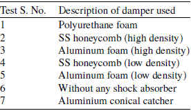
For each test, the space inside the catcher was filled with different damper materials. For test 1, polyurethane foam was used. For the second and third tests, high-density Stainless Steel (SS) honeycomb and aluminum honeycomb were used followed by low-density SS honeycomb and aluminum foam for test 4 and test 5, respectively. Test 6 was carried out without any material inside the catcher element. The last experiment was done by placing an aluminum catcher inside the catcher. The details of the different tests with different damper materials are given in Table 2.
Detail of shock sensor.

Details of test articles

Shock attenuator structures before and after firing.

4.1.6 Results and discussion
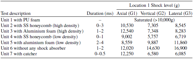
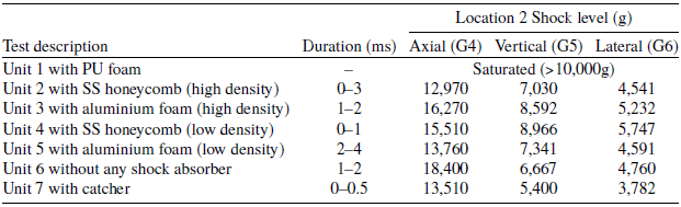
All the tests were successful with proper actuation of the pin puller mechanism thereby unlocking the rigid connection. The shock data for all these tests were recorded and compared. The post-test condition of the hardware is shown in Fig. 6. The pyro shock data shows not much improvement in the reduction of shock levels. The shock data recorded for all the tests are given in Tables 3 and 4. The maximum shock recorded in each test is plotted in Fig. 7. From the shock response spectrum (SRS) graph (as shown in Fig. 8), none of the attenuators had an appreciable impact on reducing the shock.
As the initial setting of the shock sensor’s measuring range was ±10,000g, for the first test (with polyurethane foam as a shock absorber) the shock levels reading got saturated as the shock levels were higher than 10,000g. However, for the succeeding tests, the range was enhanced to ±30,000g and the test data was recorded successfully. The shock in the axial direction is the main component as it is aligned in the direction of the pyro cartridge, which in turn transmits the shock to the surrounding components.
Shock levels in location 1 of the different shock attenuation configuration

Shock levels in location 2 of the different shock attenuation configuration

Comparison of the shock data in axial direction for various configurations.

From the test data, the SRS has been plotted for all the test configurations. It can be seen from the SRS that most of the configurations have shock levels of the same amplitude for various frequencies.
Shock response spectrum (SRS) plot of the test with different shock attenuators.

Based on the above experiments, it was found that there is no appreciable reduction in shock levels by the use of shock absorbers for the pin puller configuration.
4.2 Experiments with dampers-pyro bolt device
The experimentation involved the use of pyro bolts, which are widely employed for stage separation mechanisms. It focused on the addition of shock absorber components to the pyro bolt device configuration. The pyro bolt device features a piston housed within a sheath that is connected to the separation bolt. When initiated, the piston propels the release bolt by shearing the locking pin, thereby generating mechanical shock due to the shear action and movement of the piston inside the pyro hardware. The various components and working principle of pyro bolt are given in Fig. 9.
Mechanism of pyro bolt, before and after the operation.

Different configurations used for shock reduction by employing dampers are given in Table 5.
Details of test articles for damper pyro bolt

4.2.1 Experimental setup
For the experiment, a heavy-duty fixture rigidly mounted to the ground was utilised, with a thick plate chosen to mount the pyro bolt, simulating the combined thickness of the sections of the stage separation hardware. Shock sensors were fixed at a near-field region. Tests were designed with two shock sensors placed in axial directions, considering the observed maximum shock in the axial direction during prior tests. The test setup and the location of the shock accelerometers are shown in Fig. 10.
Test setup and location of the shock sensors near the field.

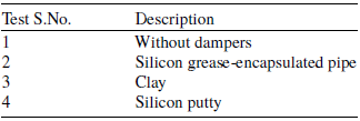
The pyro bolt was fixed to the plate and applied with the rated torque for all the tests. The shock sensors were also rigidly fastened to the base plate, and all tests were repeated in the same setup to ensure consistent conditions. Both the shock accelerometers (G1 and G2) were placed at a radial distance of 80 mm (near field region) from the central portion of the pyro bolt, one placed on top and the other placed at the bottom of the plate. These locations were selected to capture the shock levels in the near-field region. For all the tests, the shock sensors were set at ±50,000g to achieve good accuracy in the reading. Shock levels were recorded and compared for different configurations, with silicon grease, putty and clay used as dampers.
4.2.2 Results and observations
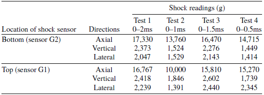
In all the tests, the pyro bolt was initiated and the separation bolt got separated successfully. The silicone grease which was encapsulated within a tube was destroyed in the test. For the test with putty, the putty has splashed out of the crevices and gap in the pyro bolt configuration. The maximum shock levels recorded for the above configurations are given in the Table 6. The comparison of the shock data in the axial direction for the top as well as the bottom sensors are plotted in Fig. 11. The post test effect of the component is shown in Fig.12.
Results of shock attenuation configuration

Maximum shock level recorded in axial direction of pyro bolt.

Post-test results of pyro bolt.

From the test data, it can be seen that the shock is getting attenuated maximum in the case of silicon grease encapsulated pipe (20.6%), followed by putty (15.09%) and clay (4.95%). The SRS of the shock data for the above tests is plotted and seen that though in lower frequency regions, there is a reduction of peak acceleration at mid or higher frequency regions, the peak accelerations exhibit similar behaviour. From all the shock data, it can be seen that there is not much shock reduction even after using dampers. The same is evident from Fig. 13 Which shows the comparison of the SRS of the different configurations.
SRS plot of the test with different damper materials.

Subsequent experiments focused on isolating the shock load path by removing certain bolting mechanisms that held the shock-producing structure to the base material.
5.0 Attenuation by shock path isolation
In the pyro bolt mechanism, upon initiation of the pyro cartridge, high-pressure gases are generated in the free volume, which causes the plunger to move upward by breaking the locking pin. This action results in the plunger hitting the check nut with an impulsive load, generating intense mechanical shock. This shock then propagates to the structure rigidly mounted to the base plate using mounting screws.
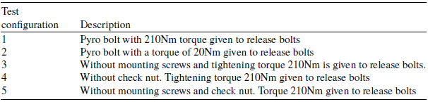
To study the reduction of pyro shock, a new set of experiments was conducted to isolate the shock source from the structure. This configuration aimed to prevent the shock generated from the explosion of the pyro cartridges from reaching the base plate and sensitive components mounted on it. Four different configurations were tested, and their details are provided in Table 7.
Details of test configurations

Figure 14 illustrates the details of each configuration before and after the initiation of the pyro cartridge. In configuration-1, the release bolt was tightened with a rated torque of 210N-m. Conversely, in configuration-2, the release bolt was tightened with a reduced torque of 20N-m to allow for looser attachment to the base plate, thereby transmitting lower levels of shocks. In configuration-3, the mounting screws were removed. In this setup, the release bolt, with the applied torque of 210Nm, allowed for complete detachment of the pyro housing assembly and the release bolt from the base plate, preventing shock transmission. Configuration-4 involved the pyro bolt assembly without the check nut, enabling the pyro holder piston to detach along with the pyro cartridge without transmitting any mechanical shock to the base plate. The release nut was given a torque of 210N-m. In configuration-5, the pyro bolt was placed on the section without the mounting screws and check nut, ensuring total separation of all components after pyro firing. The release nut received a torque of 210N-m. It’s worth noting that while these configurations are not feasible for actual stage separation designs, they were tested to study the effect of shock attenuation by removing the rigid connection of the shock load path.
Pyro bolt before and after testing for configurations 1-5.

M20 pyro bolt with configurations 3, 4 and 5, respectively.

The shock isolation test conducted in configuration-5 represents an extreme case where no contact exists between the pyro bolt and flange after release. Other methods of shock attenuation would be subsets of the aforementioned configurations. Some of these configurations are depicted in Fig. 15. The same shock sensors used in previous experiments were employed for these configurations, placed as close as possible (60mm) to accurately capture the shock within the near field region. Additionally, the shock sensors were set to record data at ±100,000g shock levels due to their proximity to the pyro cartridge.
5.1 Test results and observations
In the shock path isolation experiments, all pyro bolts were initiated and the shock data was successfully recorded. The test results of the above configuration are given in the Table 8. The maximum shock levels are shown in Fig. 16.
Test results of the different isolation configuration

The test results are promising among all the previous test methods tried out. The shock attenuation observed with reduced tightening torque is 26.3%, for configuration-3 without mounting screw has shown a 37.24% reduction, without check nut configuration has shown a 21.07% shock reduction while that for configuration-5 which is without check nut and mounting screw has shown 13.23% shock attenuation. The maximum shock levels recorded for the current set of experiments are plotted in Fig. 16. The shock response spectrum of the shock data is plotted in Fig. 17. From the SRS plot, it can be seen that there is a considerable reduction of maximum shock levels at low and mid-frequency regions. However, at high-frequency regions, the shock peaks are almost similar. The isolation of the shock path helps in shock attenuation, as suggested by many researchers [Reference Youn10, Reference Ming, Qianguang, Liqiang and Xinbo11, Reference Huan, Tianxiong, Shuhong, Changjiang and Qingming13] as well as rocket stage separation designers. However, the level of attenuation of the shock is not an order reduction as proposed initially. Hence there was a requirement to explore other means to reduce shock, i.e. by shock source attenuation method.
Maximum shock level recorded for different configurations.

Comparison of the SRS with different shock isolation configurations.

6.0 Interpretation from test results with shock absorbers, dampers and load path isolation
Based on the experimental results from the pin-puller shock absorber configuration, pyro bolt damper configuration, and pyro bolt shock path isolation configuration, it is evident that there is a reduction in shock levels observed, although it is not of significant magnitude. The shock data from all these experiments were thoroughly analysed, leading to the following inferences. Most of the test data revealed two types of shock level patterns. A typical shock plot, as presented in Fig. 18, consists of two regions, part A and part B. Part A corresponds to the shock due to the initiation of the explosive inside the pyro cartridge, while part B is due to the shearing of the lock pin and the impact of the piston against the separation bolt. When the electrical signal is given to the pyro device, the charge mass inside the pyro cartridge initiates, thereby generating high levels of explosive shock (as represented by part A of Fig. 18). The high-pressure gas produced by the explosive charge mass initiates the pyro mechanism, which also generates shock due to the impact of mechanical components (represented by part B of Fig. 18). This implicit working principle of the pyro cartridge along with mechanical movement is evident in part A and part B of the shock pattern. The same behaviour has also been observed in test reports of most of the actual fired pyro devices. Bateman et al. [Reference Bateman, Himelblau and Merritt23] have described that pyro shock data has demonstrated three events, pyro event, event due to bolt retract/shell eject, and third event due to bolt lock. Among the three events, the explosive event occurs first and is the most severe. In similar lines in the experiments conducted so far, it is generally observed that the shock generated due to the mechanical component is lower than the shock level generated by the explosive.
Typical shock plot with pyro-actuated separation bolt.

It is evident that none of the methods employed to reduce shock by using shock absorbers, dampers and shock path isolation has a significant effect in decreasing the explosive shock component. As the explosive shock levels are higher compared to the reduced mechanical shock levels, the presence of shock-attenuating material in the pyro device has not shown a pronounced effect in reducing the shock generated due to the explosive component. Therefore, the emphasis in the final set of experiments is given to altering the initiation method for actuating the mechanism, categorised as shock reduction by shock source attenuation
7.0 Attenuation of shock source
From the above observations, it is clear that the pyro cartridge generates high-pressure gases in a few microseconds, which is sufficient to initiate the release bolt. This detonation phenomenon is associated with high levels of shock that propagate through the medium, potentially damaging sensitive equipment. Implementing alternative initiation methods like pneumatic initiation is expected to slow down this pressurisation process, thereby reducing the shock levels to a significant extent. Many modern spacecraft systems employ a design with pneumatically initiated separation mechanisms [Reference Floyd and Owens18, Reference Cebrian, Halter and Gerngross24, 25]. Before the pneumatic system can be designed, it is essential to determine at what pressure the pyro bolt is initiated. Therefore, an experimental study was initiated to first determine the minimum pressure required to initiate the release bolt. The experimental set up is shown in Fig. 19 and Fig. 20. Additionally, the shock parameters were monitored to identify any reduction by using pneumatic initiation. The first test involved subjecting the separation bolt directly to a pneumatic pressure of 35MPa, and the shock was recorded. Subsequently, the test was repeated employing a gradual increase in pressure to identify the threshold at which initiation takes place. This study provides confidence regarding the maximum pressure at which the release bolt is initiated. The same test setup utilised in the previous experiment with the pyro bolt has been employed for this test.
7.1 Test objectives
-
• To measure the shock generated (with pyro cartridge) and the reduction of it by employing pneumatic pressure actuation for pyro bolt operation.
-
• To the pneumatic pressure is increased from 13MPa in steps of 0.5MPa, which is programme controlled.
-
• To check the structural integrity of hardware after tests.
-
• To measure the shock by installing shock sensors in the vicinity of the near shock field.
-
• To carry out two initiation tests with pyro cartridge and five tests with pneumatic initiation.
Test setup of pyro bolt with pyro cartridge.

Connection details and test scheme of pyro bolt with pneumatic initiation.

Test results of pyro and pneumatic initiation configurations

7.2 Test results
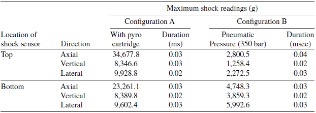
The separation bolt got separated during firing with the pyro cartridge. The pneumatic test was conducted by opening the gas valve in manual mode at 35MPa pressure. On the sudden opening of the pneumatic valve, the mechanism was initiated, and the separation bolt was released and ejected. The shock levels of the above configurations are given in the Table 9.
The major shock is recorded in the axial direction. In the pneumatic testing, it is seen that there is an order reduction of shock levels. In addition, as the pressure transducer mass is significantly larger compared to that of the pyro bolt mass, the shock was observed to be of higher magnitude in the lateral direction compared to that in the axial direction.
The two tests confirm the reduction of shock (by one order less) generated during the separation of the pyro bolt from that fired with the pyro cartridge to that pressurised by pneumatic means. The pneumatic-initiated pressure is 29.48MPa. This is attributed to the slow rate of pressurisation as compared to that of pyro cartridge firing. The slow rate of pressurisation enables the shear pin to break slowly and the pyro holder piston to hit the check nut.
The test was repeated another four times to record the pneumatic pressure which initiates the mechanism, in addition to the shock recordings. In total two tests were carried out with a pyro cartridge and five tests with pneumatic initiation were carried out. The test results are tabluted in Table 10 and the shock levels are plotted in Fig. 21. The shock levels as well as the shock response for both the tests are plotted in Fig. 22and Fig. 23 respectively.
Test results of the second test with pneumatic initiation

Maximum shock levels in the axial direction in a different configuration.

Shock details of pyro bBolt fired with (a) pyro cartridge, (b) pneumatic initiation.

SRS of test with pneumatic initiation.

8.0 Conclusion
The present research aims to address the pyro shock generated during the stage separation event in aerospace vehicles. A series of innovative experiments were conducted to evaluate the impact of shock reduction in the near-field area of pyro devices through the use of shock absorbers and dampers. Various shock-attenuating mechanisms, including dampers, metallic foam structures, viscous materials, and dampeners, were utilised to measure their effectiveness in reducing shock. Additionally, the stiffness of joints in the vicinity of the pyro shock was intentionally decreased to analyse its influence on shock mitigation. The study also explored the effects of removing rigid connections, such as bolted joints, from pyro-actuated systems on shock reduction. Despite thorough testing with various materials and techniques, achieving a significant reduction in shock levels remains a complex challenge. However, the findings indicate a notable decrease in pyro shock when transitioning from a pyro explosive charge to a pneumatic system. The results from the tests utilising pneumatic initiation reveal that replacing the conventional pyro explosive charge initiation with a pneumatic system significantly lowers pyro shock levels. A comprehensive analysis was performed through experiments to identify effective strategies for achieving substantial shock reduction. Moreover, it was noted that pyro-actuated separation devices exhibit considerable variability in shock test results, a trend not seen in pneumatic-initiated devices. This research was conducted on actual pyro-initiated hardware, measuring shock levels in both near-field and mid-field regions, thus making a valuable contribution to the existing literature.
Acknowledgments
The authors express their gratitude to the director of Advanced Systems Laboratory, Hyderabad, India for guidance, motivation and continuous support in reviewing the work. They also express their sincere thanks to technology director of DoFS/DRDL, Hyderabad, India for their instrumentation support for the testing. In addition, the authors express their gratefulness to the head of Aerospace Mechanisms Division to allow them to carry out all the experiments at their facility. Finally, the authors thank all scientists and staff, who are both directly or indirectly involved in the completion of this work.