I. INTRODUCTION
Increasing demand on automotive radars to improve road safety is currently being seen all over the world. Attractive functions like anti-collision, lane change assistance, and blind spot monitoring have been employed in these devices. Advanced cruise control systems employing “long-range radar” operating at 77 GHz enable a vehicle to maintain a cruising distance from a vehicle in front. Anti-collision “short-range radar” at 79 GHz is being developed as a part of a system to warn the driver of a pending collision, enabling automatic braking in case of inevitable collision to minimize injury to passengers. Such systems have been implemented in several high-class vehicles, like Mercedes S-class, Volkswagen Phaeton or Audi A8. Nevertheless, existing automotive radar technologies are not mature yet. A great amount of further development in adding more functions, extending detection range, and increasing resolution in target range, azimuth angle as well as Doppler frequency is needed to ensure reliable driver assistance and safety systems.
Electrically steerable phased array antennas are regarded as one of the most promising solutions for significantly enhancing the performance of automotive radars. Various technologies can be employed to implement electrically steerable antennas at different frequencies. However, conventional solid-state switchable or tunable components are certainly not a good option at millimeter-wave frequencies, because of their significant losses. RF microelectromechanical systems (MEMS) switches have shown excellent performance in terms of isolation, insertion loss, linearity, and nearly-zero DC consumption at this frequency range. But commercially available MEMS switches are still limited by the maximum operational frequencies of approximately 40 GHz, and successful integration of MEMS devices to other RF subcomponents at very high frequencies is challenging.
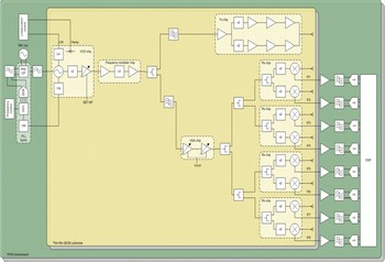
Beam scanning of phased array antennas can also be implemented at baseband. Digital beamforming (DBF) is a fast developing technology, and enables full utilization of the degrees of freedom in the array. Compared to traditional techniques, this technology can lead to significant improvements in adaptive pattern nulling, space-time adaptive processing, beamforming of simultaneous multiple independent beams, and direction finding (DF). Due to its high flexibility, DBF might find use in a broad range of phased array antenna applications (Fig. 1).
Automotive radar system architecture, using Digital Beamforming (DBF).

The digital beam forming architecture has high integration potential, both at the MMIC and module level, as well as its flexibility in the digital domain. By using this concept a complete automotive radar front-end transceiver for the 79 GHz band has been demonstrated [Reference Platt, Pettersson, Salter, Jakonis and Haglund1]. Other antenna solutions like quasi-optical lens-based antennas have been implemented previously for beam focusing and steering but such solutions tend to be larger and more expensive [Reference Gresham2].
II. SILICON AND BENZOCYCLOBUTENE (BCB) PROCESS LAYERS
The use of low resistivity silicon wafers is widely spread in the microelectronic industry making them very attractive in many different application areas. Integrated antenna technology, for applications in the millimeter wave frequency region, implemented on low resistivity silicon, suffer from low radiation efficiency. By using different micromachining techniques, the efficiency has been improved and several low resistivity silicon antennas have been successfully designed and demonstrated [Reference Cheng, Rydberg, Hallbjorner, Pettersson, Salter and Platt3].
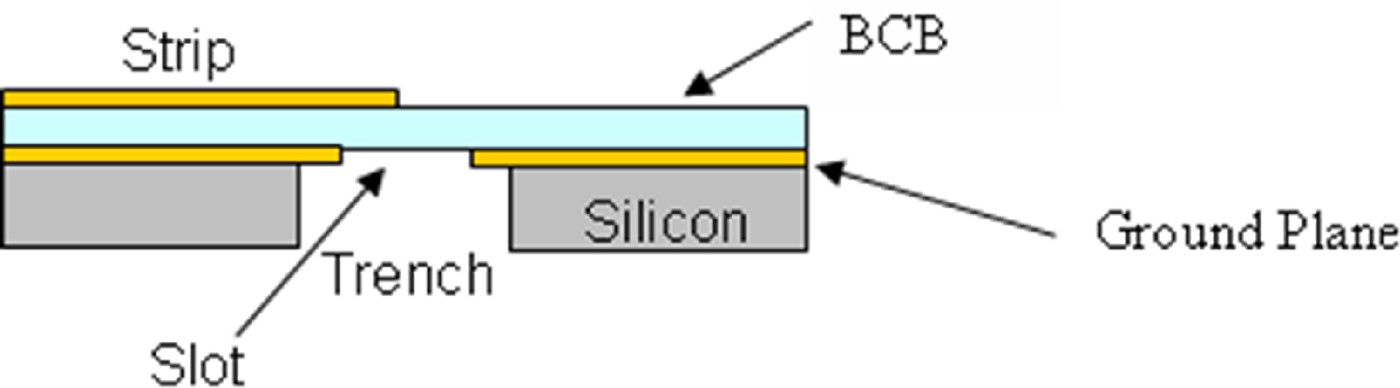
The manufactured silicon and BCB substrates are processed in Acreo's thin film processing facility. The manufactured BCB thickness for these antennas is 2 × 14 µm in total, with an ɛr = 2.65 and a tan δ = 0.0008. The thickness of each copper layer is 1 µm. The low resistivity silicon has a bulk resistivity of 5–20 Ω cm and a thickness of 325 µm. The build-up is shown in Fig. 2. The simulated 50 Ω microstrip line width is 75 µm which corresponds to an attenuation of 0.2 dB/mm at 79 GHz. The measured insertion loss was 0.25 dB/mm at 79 GHz.
Low resistivity silicon and BCB substrate build-up.

III. ANTENNA DESIGN CONSIDERATIONS
A) Single slot antenna element
The requirements of the antenna were to choose an antenna element for the 77–81 GHz band that can radiate ±90° in the azimuth. Possible antenna element candidates are dipole, patch, and slot radiators. The dipole element solution will require a balanced configuration for the feed network causing a too complex layout in planar technology. The patch element solution does not suffer from this problem, but, since the impedance bandwidth of the patch is less than 1 GHz, the patch element solution will not satisfy the frequency requirements. The adequate candidate is the horizontally polarized slot element solution which offers both a wide E-plane pattern and a large impedance bandwidth.
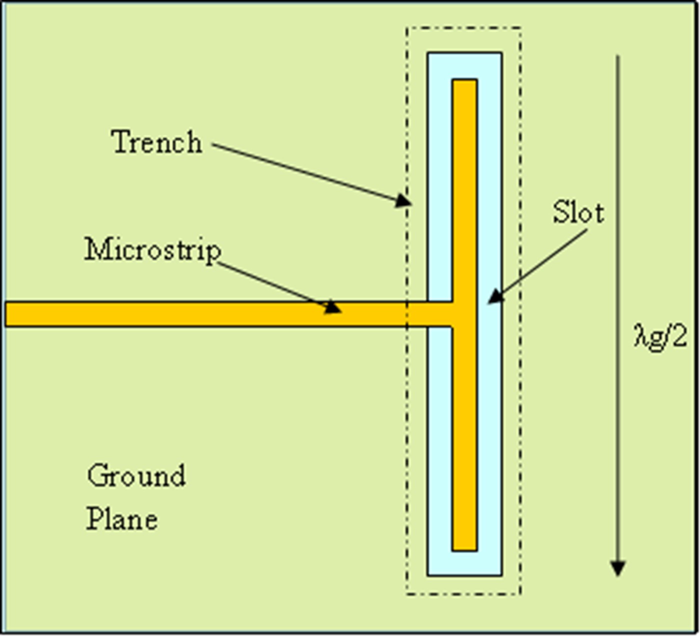
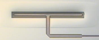
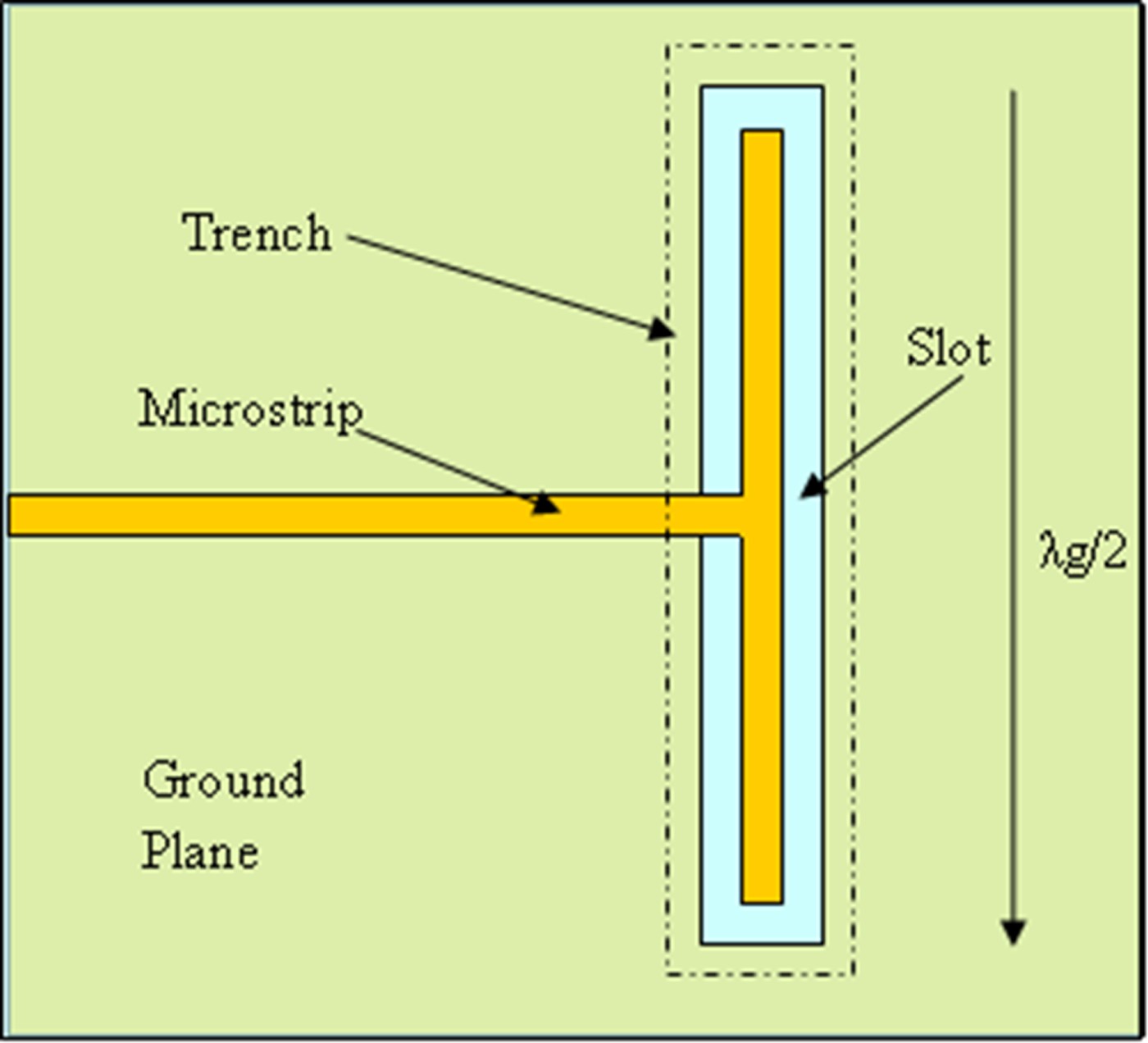
Since the standard half wavelength slot antenna suffers from high input impedance when it is realized with an air dielectric, a folded half wavelength slot radiator is used instead to reduce the impedance at resonance [Reference Newman and Thiele4]. The designed slot element is shown in Figs 3 to 5.
Top view of a single slot antenna element.
Cross-section of a single slot antenna element.
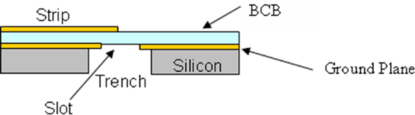
Photo showing the top view of a single slot antenna element.

The size of a single element is 50 × 1600 µm, slot size 150 × 1700 µm and trench size 600 × 2400 µm.
B) Antenna feed network
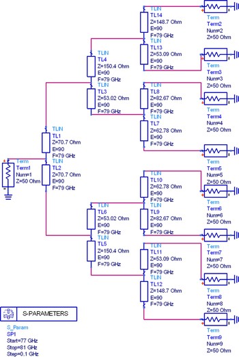
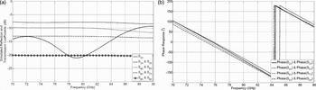
Since slot antenna arrays will be designed, a distribution network must be designed. Digital beam steering will be used in the azimuth plane of the array, while a fixed radiation pattern in the elevation plane is specified. To accommodate these requirements, the antenna is divided into vertical subarrays, each connected to a receiver channel by a transmission line. Two feed network topologies can be considered for the vertical subarrays, a corporate feed using power dividers or a series feed using a tapped transmission line. Due to the requirement of low squint, a corporate feed network fed at the center point of each array has been chosen, even though this topology leads to a higher insertion loss in the feed network due to longer transmission lines. In real applications, the presented module will be installed with all the subarrays perpendicular to the horizontal plane. The single TX array will transmit RF power covering a broad sector in the horizontal plane, while the RX arrays will be horizontally steered using DBF technique to detect the reflections from pedestrians, bicyclists, motorcyclists, or other vehicles in front. In the vertical plane, a very directive antenna beam, approximately 10° half power beamwidth, is required. In this way, the radar detection range can be increased and the reflections from the ground and some regular objects above the roads, including bridges or traffic signs, will be suppressed. For the same reasons, excitations of the radiating elements from the parallel feed network are optimized to reduce the sidelobe levels of the arrays instead of maximizing the antenna gain. Hence, the radiators in TX and RX arrays are not uniformly excited. Figure 6 shows a schematic of the distribution network with the microstrip line impedance indicated. Figure 7 illustrates the layout of the feed network that is horizontally symmetrical, i.e. symmetrical around P1. Simulated reflection and transmission coefficients as well as phase response are presented in Fig. 8
Schematic of the simulation model used for the RX and TX array feed network, with impedance levels indicated.

Layout of the simulation model used for the RX and TX array feed network.

Simulated (a) reflection and transmission coefficients, and (b) phase response of the RX and TX array feed network.

IV. TX AND RX ANTENNA IMPLEMENTATION
A) TX array antenna
The TX antenna consists of an array of 1 × 8 single slot antenna elements according to Fig. 9 below.
Layout of the TX array.

The antenna should provide full ±90° illumination of the azimuth plane, while having the same elevation pattern as the receive array. The transmitter antenna is designed as a single column of the receive array in order to fulfill these requirements.
The feed network for the TX array is identical to the network used for the receiver. It is possible to add a power amplifier at the center of the array to compensate for the 3 dB loss associated with the edge to center feed line.
B) RX array antenna
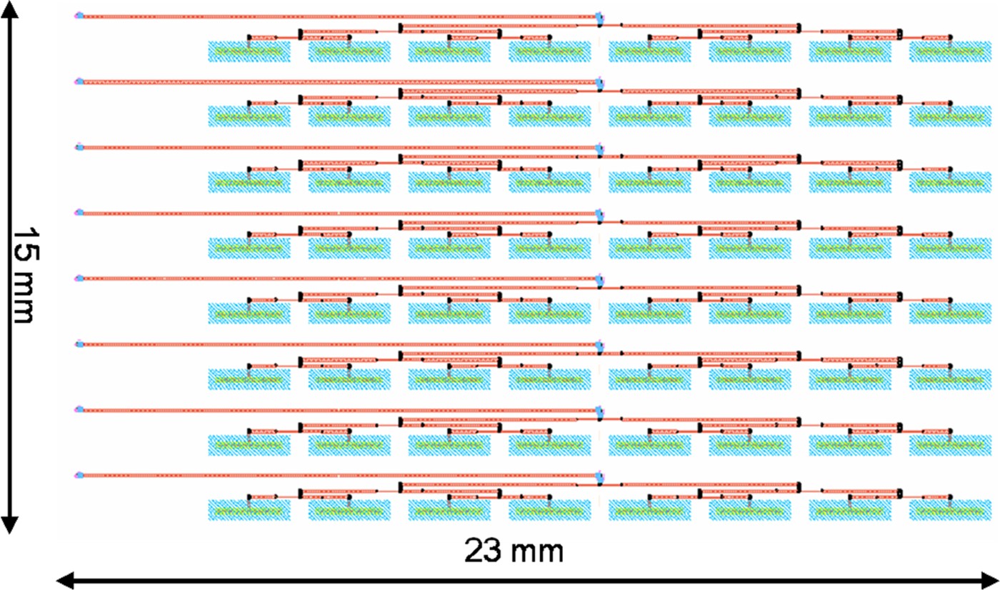
The RX antenna consists of an array of 8 × 8 single slot antenna elements according to Fig. 10 below.
Layout of the full 8 × 8 RX array.
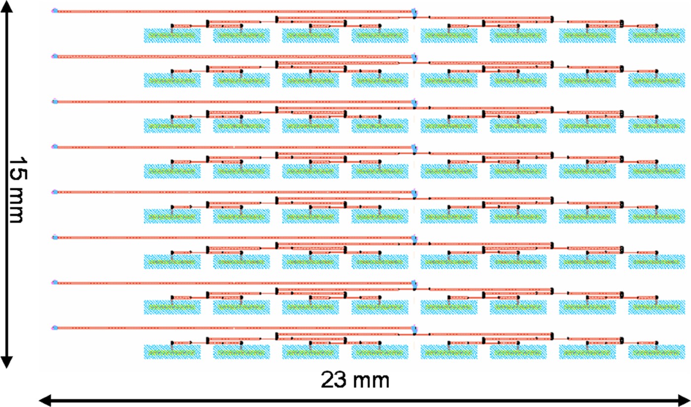
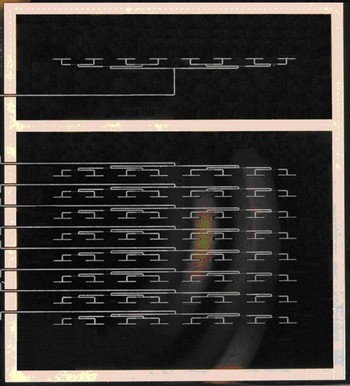
Figure 11 shows the complete manufactured TX and RX antenna with a metal frame foot print for the metal back cavity assembly. The metal frame is grounded using microvias to the ground plane.
Photo of the complete slot array antenna: TX 1 × 8 array and RX 8 × 8 array with metal frame for cavity assembly.

V. CAVITY-BACKED ANTENNA
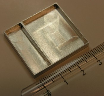
By introducing a metallic cavity, the gain of the TX and RX antenna could be increased ideally by 3 dB. However, due to losses, a gain increase of approximately 2 dB is more likely. The cavity is shown in Fig. 12.
Metal cavity for increasing the gain of the antenna.

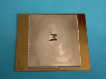
The metal cavity is mounted on the top of the TX and RX arrays using conductive adhesive. The TX and RX arrays have separate cavities for decreased coupling between the TX and RX antennas. The thickness of each cavity is λ/4.
A) Parallel plate mode suppression
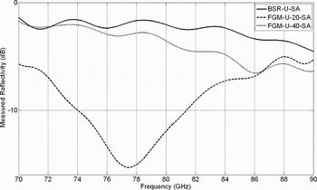
The cavity may cause the occurrence of parallel plate modes, which can negatively affect the performance of the antenna. Thus millimeter-wave absorbers are proposed to cover the inner surfaces of the cavity to suppress the potential cavity modes. Conventional carbon powder-based foam-like absorbers are not suitable to be used as damping materials at 79 GHz. Instead different rubber-like thin sheet absorbers, Eccosorb, from Emerson & Cuming, are tested at the frequency of operation (see Fig. 13). It is clearly shown that the FGM-U-20-SA exhibits the highest attenuation around 79 GHz. Thus, this type of Eccosorb is chosen for the implemented metallic cavities.
Measured attenuation of different Eccosorb.

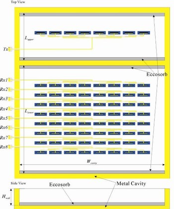
Parallel plate modes can be reduced using Eccosorb assembled inside the cavity, see Fig. 14 below.
Metal cavity with Eccosorb assembled to reduce parallel plate modes.

The drawback with using Eccosorb is that the maximum gain increase of 3 dB will not occur due to absorption by the Eccosorb.
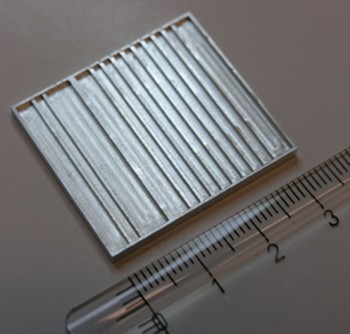
Another way to reduce the parallel plate modes is to introduce a ribbed structure of metal bars inside the cavity as shown in Fig. 15. This construction will increase the gain performance and also reduce the coupling between the slot elements.
Metal cavity with implemented metal bars for parallel plate mode suppression.

Figure 16 below shows the back cavity mounted onto the complete antenna.
The complete slot array antenna and metal cavity assembly.

VI. MEASURED AND SIMULATED RESULTS
The following parts have been verified: single slot element, TX 1 × 8 antenna array, and RX 1 × 8 subarrays. All reflection measurements were made with a network analyzer in the frequency range 70–90 GHz. The gain measurements have been made at 79 GHz.
A) Measurements without cavity-backed antenna
1) Single slot antenna element simulations and measurements
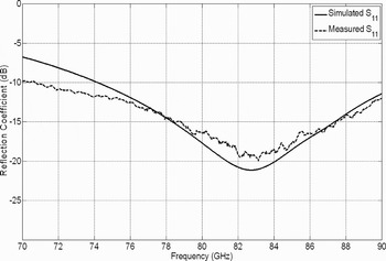
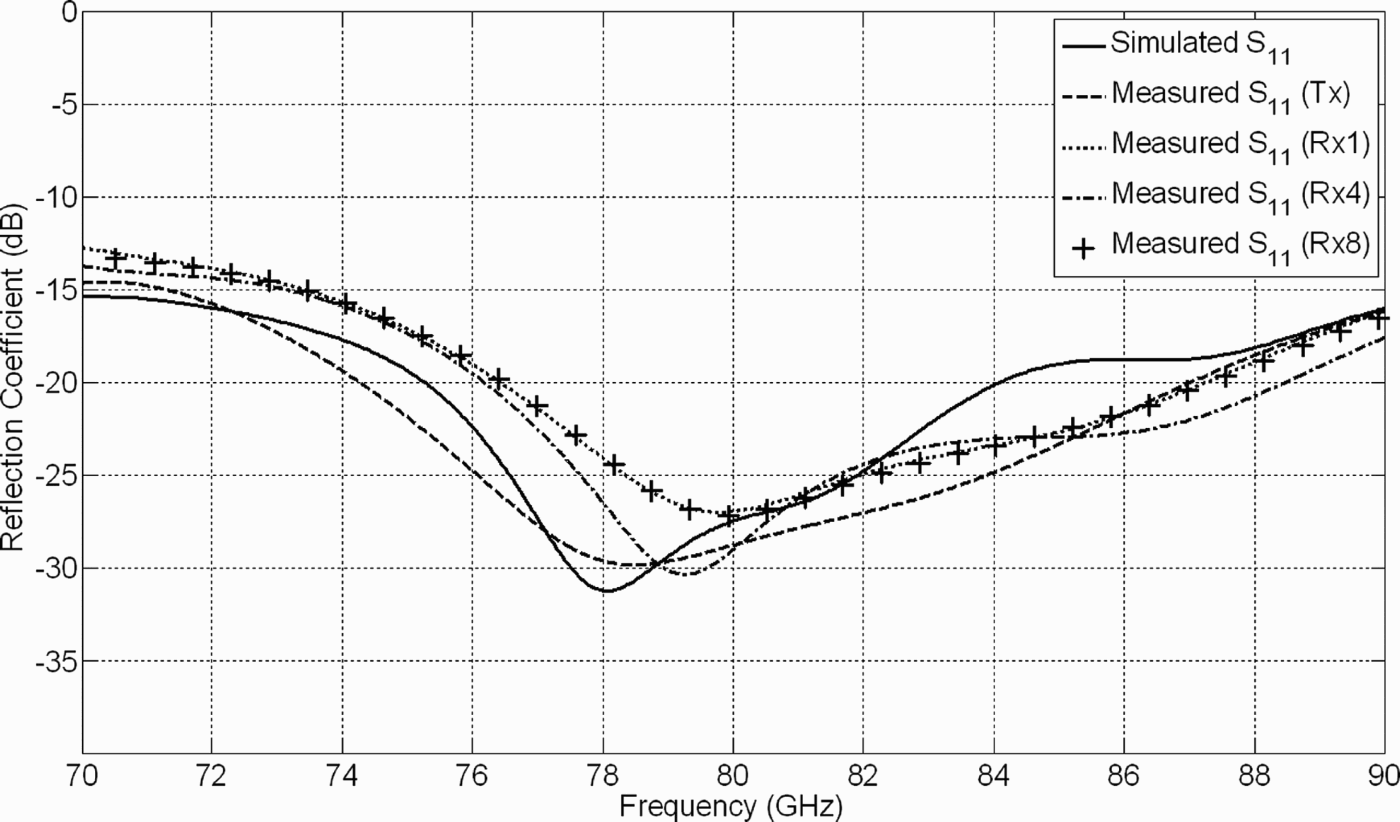
The return loss of an individual antenna element has been tested to verify the correct impedance and resonance frequency as they are essential for correct operation of the feed network. Figure 17 demonstrates that the measured and the simulated results are very consistent.
Simulated and measured reflection coefficients of the single slot antenna.

2) Measurements and simulation of a RX 1 × 8 subarray
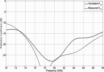
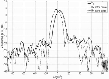
Measurements of the complete 8 × 8 array have not been performed due to the complex measurement set-up. Instead measurements have been made on single RX 1 × 8 subarrays. The measured results are very promising. The measured reflection and E-plane pattern are shown in Figs 18 and 19.
Simulated and measured reflection coefficients of the RX subarray.

Measured E-plane co-polarization of the TX and RX array antennas at 79 GHz.

The measured reflection coefficient is better than 10 dB in the frequency range 70–90 GHz.
Measurements of the gain have been done in the E-plane co-polarization for the TX 1 × 8 array and two RX 1 × 8 subarrays. The measured maximum gain is about 4.5 dBi at the frequency 79 GHz. The single 1 × 8 array measurements of the TX and RX antennas have similar behavior. Higher gain could probably be achieved by increasing the trench size as less power is absorbed by the silicon substrate.
3) Measurement of isolation between two neighboring RX columns
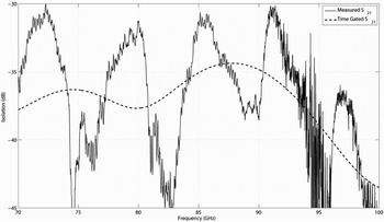
Isolation is a very important parameter when it comes to obtaining good antenna performance. Bad isolation will cause ripple in the radiation pattern, thus degrading antenna performance. Figure 20 below shows that the measured isolation between two neighboring RX antenna columns is better than 30 dB.
Measured isolation with and without time gating.

B) Measurements with cavity-backed antennas with no Eccosorb
The addition of a metallic back cavity may enable an increase of the antenna forward radiation. Unwanted cavity modes may be introduced as a result of the presence of the large metal cavity. These most probably will degrade antenna radiation performance.
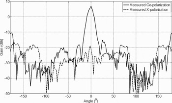
The measured maximum gain of the R × 4 subarray row in the E-plane, shown in Fig. 21, is approximately 6.6 dBi, which is roughly 2 dB higher than the corresponding measurement shown in Fig. 19. Moreover, due to the presence of unwanted cavity modes, the backward radiation is around 10 dB larger compared to the results of Fig. 19.
Measured E-plane radiation patterns of the RX4 array antennas backed by a large metal cavity.

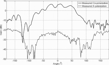
Measured H-plane radiation patterns are shown in Fig. 22. Strong ripples, as well as increased back radiation can be seen in the co-polarization. These may also result from the unwanted cavity modes.
Measured H-plane radiation patterns of the RX4 array antennas backed by a large metal cavity.

C) Measurements with cavity-backed antennas with Eccosorb present
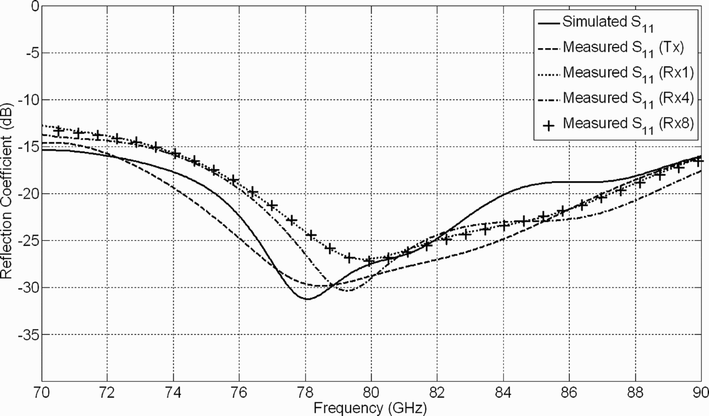
Simulated and measured reflection coefficients are presented in Fig. 23. As expected, the results are very similar to the ones shown in Fig. 18, where the TX/RX array antennas achieve broad impedance bandwidth within the frequency range of 70–90 GHz.
Simulated and measured reflection coefficients of the TX/RX array antennas with a large metal cavity covered with Eccosorb.
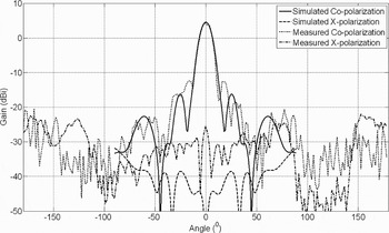
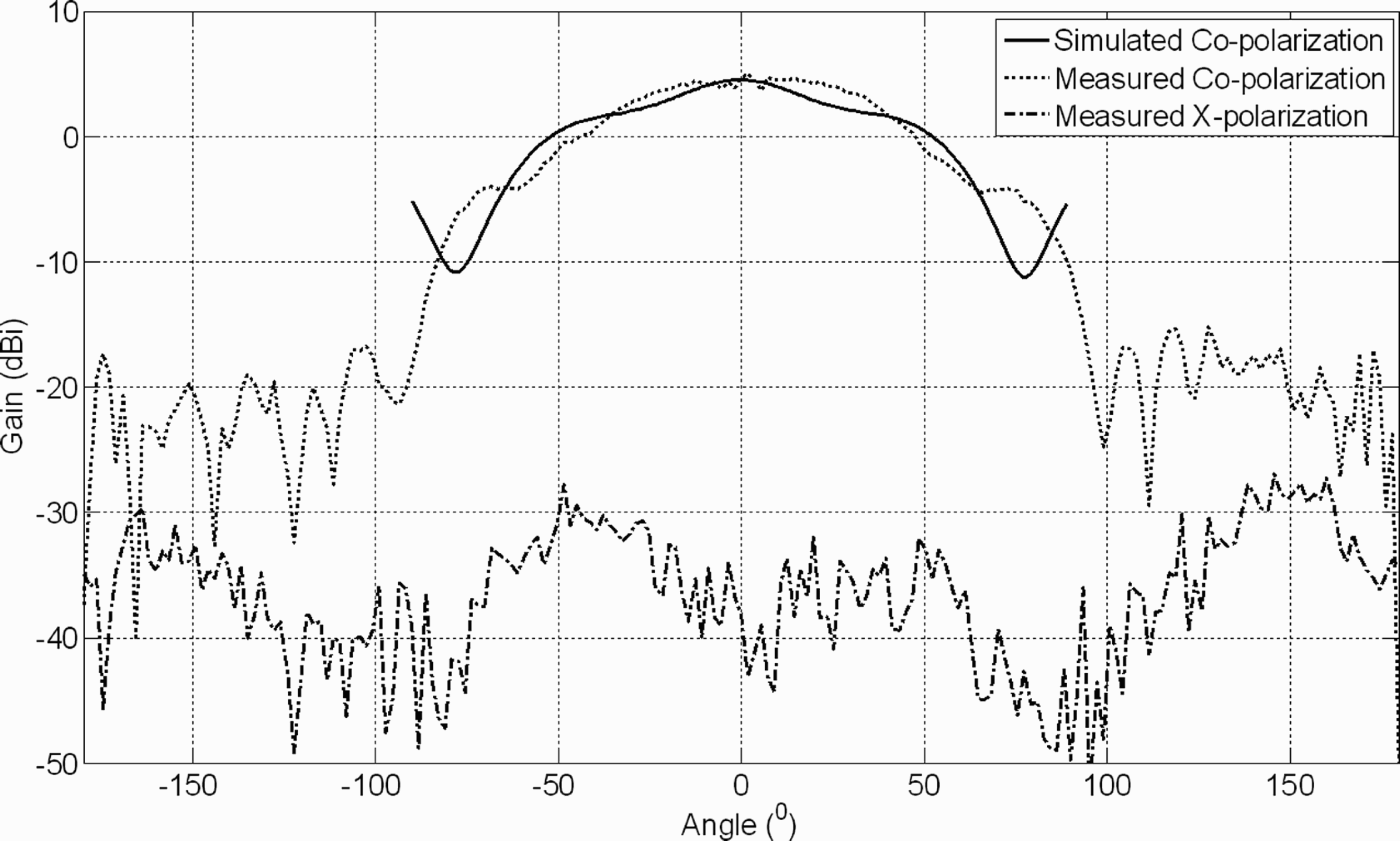
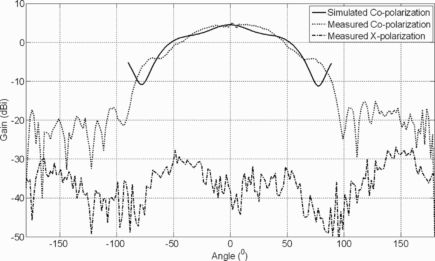
Apart from the port impedance, the antenna radiation patterns in the E- and H-planes have also been analyzed (see Figs 24 and 25). The maximum antenna gain and sidelobe suppression are found to be 4.5 dBi and 17.5 dB in the E-plane, respectively. Moreover, the backward radiation is 20 dB lower than the forward radiation. In the H-plane, the antenna features very broad beam coverage. Small ripples can be seen in the measured radiation patterns, which can be explained by the reflections from the probe holder and RF probe. Obviously, the x-polarizations are much lower compared to the co-polarizations in both planes.
Simulated and measured E-plane radiation patterns of the RX4 array antennas with a large metal cavity covered with Eccosorb.

Simulated and measured E-plane radiation patterns of the RX4 array antennas with a large metal cavity covered with Eccosorb.
D) Measurements with cavity-backed antennas with metal bars
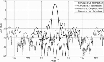
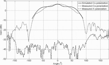
Simulated and measured E- and H-plane radiation patterns of the RX4 array antenna are demonstrated in Figs 26 and 27. The measured results indicate that the antenna exhibits a maximum gain of 6.6 dBi, E-plane side lobe suppression of 17 dB and back radiation of approximately −20 dBi.
Simulated and measured E-plane radiation patterns of the RX4 array antennas backed by a large metal cavity with metal bars.

Simulated and measured H-plane radiation patterns of the RX4 array antennas backed by a large metal cavity with metal bars.

Smooth curves without strong ripples can be observed in the measured H-plane radiation patterns of Fig. 27. The results are much better compared to the corresponding measurements in Fig. 22.
E) Simulated results of RX 8 × 8 slot array antenna
The simulated antenna efficiency is 13%. This value is mainly determined by the high network losses. Simulations also show a total peak gain of 17 dBi for the complete RX 8 × 8 array.
VII. CONCLUSIONS
An 8 × 8 RX slot array antenna and a 1 × 8 TX slot array antenna for the 79 GHz automotive band have been successfully simulated, built, and tested. The 1 × 8 RX and 1 × 8 TX measurements show a maximum gain of 4.5 dBi. By introducing a cavity-backed antenna the gain could be increased by at least 2 dB. Side lobe suppression, back radiation and parallel plate modes were also successfully rejected by implementing metal bars inside the metal cavity.
In future development, it would be desirable to reduce the high Copper loss in the feed network. This could be done by using a thicker substrate, thereby increasing the width of the 50 Ω microstrip.
ACKNOWLEDGEMENTS
This research work has been performed as a part of the MEDEA+ Hi-Mission project [5]. We thank MEDEA+ for the approval, support and review of the Hi-Mission project as well as the public authorities of Sweden and Vinnova for their economical contribution to the Hi-Mission project.
 Lars Pettersson received the M.Sc. degree in microwave engineering from Chalmers University of Technology 1998. He joined Ericsson Microwave Systems in 1998, Gothenburg, where he worked with communication links and GaAs MMIC development for radar modules. From 2002 to 2006, he worked at Autoliv Electronics, Linköping, Sweden, where he was engaged in designing antennas and RF electronics for the automotive industry. Lars is currently employed at Acreo AB in Norrköping, Sweden. His main interests are development of integrated antennas, radar front-ends, and integrated circuits for microwave and millimeter wave frequencies.
 Shi Cheng received the B.E. degree in radio engineering from Southeast University, Nanjing, P. R. China, in 2003, the M.Sc. degree in engineering physics, and Ph.D. in microwave technology from Uppsala University, Uppsala, Sweden, in 2006 and 2010, respectively. Dr. Cheng is currently with Advanced Technology at Laird Technologies, Kista, Sweden. His research interests include integrated antennas for various wireless sensor applications, RF microelectromechanical systems (MEMS) based reconfigurable antennas and circuits, electrically steerable or switchable array antennas, millimeter-wave antennas and circuits, and stretchable RF integrated circuits and antennas. Dr. Cheng has authored and co-authored more than 35 scientific papers in various journals and international conferences, and is the main inventor of two international patents. Moreover, he serves as a regular reviewer for several peer-reviewed journals. In addition, he is the recipient of the Outstanding Chinese Oversea Graduate Student Award from the Chinese Government in 2009.
 Michael Salter has B.S. and M.S. Engineering degrees from the University of New Hampshire, USA and over 22 years of research, engineering, and management experience, both in USA and Europe. He is a member of IEEE. His career in the electronics field began with Ericsson Telecommunications in the areas of analog and mixed mode simulation for telecom switching infrastructure hardware. It continued with engineering and management positions at Motorola Personal Communications in the area of RF module, electronic packaging, and components for CDMA and GSM cellular phones. At the Motorola Advanced Technology Centre, he managed a group of RF design and test engineers, and led a large corporate wide program to introduce high density interconnect, or HDI, PCB technology into Motorola's first cellular phone transceiver. He currently manages the Microelectronics group at the Swedish Research Institute, Acreo AB in Norrköping, Sweden, where he leads research in advanced integration for high frequency and sensor applications.
 Anders Rydberg received the M.Sc. degree from Lund Institute of Technology, in 1976 and the Ph.D. degree from Chalmers University of Technology, Göteborg, Sweden, in 1988. From 1977 to 1983, he worked in development and research at the National Defence Research Establishment, ELLEMTEL Development Co., and the Onsala Space Observatory. In 1991, he was appointed Docent (Associate Professor) at Chalmers University of Technology. Between 1990 and 1991, he worked as a Senior Research Engineer at Farran Technology Ltd, Ireland. In 1992, he was employed as an Associate Professor and in 2001 as a Professor in applied microwave technology at Uppsala University.
 Duncan Platt received his B.Sc. from the University of Strathclyde, Scotland, in 1986. He is a member of IEEE. He started his career working with optical and vibratory gyroscope technology development at the company formerly known as GEC Ferranti in Edinburgh, Scotland. In 1994, he joined Ericsson Telecom in Norrköping, Sweden, working as an electronic design engineer in the development of high data rate fiber optic line terminal equipment. From 1997 to 2008, he was a consultant at the Swedish consultancy company ÅF, where, among other things, he was responsible for the hardware design of one of the world's first automotive safety telematic systems for Autoliv Electronics and Volvo. He is currently employed as a project manager in the Microelectronics group at the Swedish Research Institute Acreo AB in Norrköping, Sweden, where he is managing several applied research projects in the areas of microwave and millimeter wave front-end technology for radar, very high data communication rate, and security imaging applications.