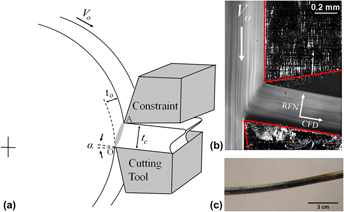

I. INTRODUCTION
Rolled sheets of ferromagnetic materials serve as magnetic cores for many important electromagnetic devices, with applications ranging from large power distribution transformers to rotating electric motors. Reference Littmann1 For improving the efficiency of these devices, the electrical and magnetic properties of the sheets composing the magnetic core must be optimized: high magnetic permeability (µ = B/H), high saturation induction (B s), low coercivity (H c), and low core loss are desired. An overarching requirement of the processing is low cost. Few alloys satisfy these application requirements better than alloys of iron with silicon (Fe–Si).
Commercial processing of Fe–Si sheet is done through combinations of multi-step hot and cold rolling. Two distinct types of sheets having vastly different structures and magnetic properties are produced. Sheets processed primarily by hot rolling are classified as non-grain-oriented (NGO) due to a weak (near random) crystallographic texture, while the application of iterative cold rolling and high temperature annealing is used to develop a strong cube-on-edge (Goss) texture resulting in grain-oriented (GO) sheets.
While these two products serve a significant application range, improvements in the properties of these Fe–Si sheets have been scarce in recent decades due to combined processing and alloy limitations. Such limitations have ignited new efforts to develop improved Fe–Si sheet for efficient electromagnetic devices with reduced core loss and large reductions in total waste electrical energy. 2 To address this initiative, an innovative, single-step cutting-extrusion process has been developed to produce sheets of Fe–Si in a single deformation step. By enabling shear textures not achievable by rolling, it is envisaged that sheet with unique metallurgical features, and nominally “soft” magnetic properties similar to the commercial rolled sheet can be realized.
II. BACKGROUND
A. Factors affecting magnetic properties
Both material structure and composition control the magnetic properties of Fe–Si sheet. Aspects of the material structure considered most important are the grain size (d) and crystallographic texture, the combination of which predominantly influences the magnetic permeability (µ), coercivity (H c), and hysteresis loss (W) properties. Perfectly isolating the independent effects of grain size and texture is difficult but studies indicate that increased grain size increases the permeability while decreasing the coercivity and hysteresis loss. Reference Herzer3–Reference Shiozaki and Kurosaki5 The mechanism of improved properties at larger grain sizes is attributed to a reduction in grain boundary area, which eases the motion of magnetic domains during microscale magnetization processes. Reference Cullity and Graham6
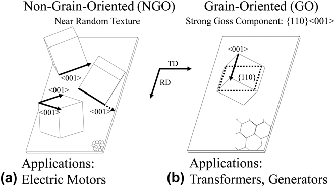
Crystallographic texture, by virtue of the intrinsic magnetic anisotropy of the α-BCC structure in Fe–Si sheet, also influences these same properties. The main objective in developing textures is the influence on the orientation of the easy magnetization directions, along 〈001〉. Perhaps the best example illustrating this is the two available commercial rolled Fe–Si sheet structures (Fig. 1). In the case of the NGO sheet, the texture is weak with a (near) random orientation of the 〈001〉 directions both in and out of the sheet plane [Fig. 1(a)], resulting in a low degree of anisotropy in the magnetic properties; the performance here is nearly independent of the applied field (H) direction. The NGO sheets are thus most commonly utilized in electric motor applications, where the field is rotating continuously. In contrast, the GO sheets [Fig. 1(b)] possess a strong Goss texture from secondary recrystallization, wherein one of the 〈001〉 directions lies along the sheet length (rolling direction, RD), leading to near ideal magnetic properties in this direction (i.e., high permeability with low coercivity and hysteresis loss). GO sheets are primarily used in power distribution transformers, where the easy magnetization direction can be configured mostly parallel to the magnetic flux direction. The GO sheets also exhibit a significantly larger grain size (d > 4 mm), by virtue of the secondary recrystallization, compared to NGO sheets (d ∼ 150 μm), although this characteristic is considered to contribute less than the texture to benefiting magnetic properties. As a whole, the essential goal of texture development in Fe–Si sheet is to reduce the misorientation of the 〈001〉 directions with respect to the applied H field.
Schematics showing (a) non-grain-oriented (NGO) and (b) grain-oriented (GO) sheet structures. Superimposed are the orientations of select 〈001〉 directions, which are responsible for the vastly different sheet magnetic anisotropies.

In addition to structure, composition also influences the magnetic properties. Alloying with silicon significantly enhances the intrinsic magnetic properties of iron by increasing the permeability, while reducing coercivity, magnetostriction and core losses—particularly important in transformer applications. Reference Chen7 Commercial rolling, however, is limited to producing Fe–Si sheet with a narrow silicon composition range (1–3 wt% Si), even though it is well-known that higher Si content alloys have superior magnetic properties. Reference Haiji, Okada, Hiratani, Abe and Ninomiya8 In fact, Fe–Si alloy with 6.5 wt% Si content is considered the best for magnetic applications. But major decrease in workability arise in alloys containing >3.5 wt% Si. Such alloys crack readily during rolling preventing their cost-effective manufacturing.
Interstitial impurities are also an important aspect of the sheet composition. Interstitials have been documented mostly as having negative effects on magnetic properties, where the local elastic strains around the misfitting solute atoms disturb the motion of magnetic domains. Properties such as permeability, coercivity, and hysteresis loss are negatively impacted as a result. Therefore, it is most critical to minimize the content of carbon, sulfur, nitrogen, and oxygen impurities. Reference Littmann1 Carbon is particularly important because, in addition to being an interstitial element, its presence in small amounts significantly increases the critical silicon content required to maintain the desired α-phase microstructure at elevated temperatures. Furthermore, C can cause precipitation of fine Fe3C particles in service over time (aging), reducing the long-term efficiency of the Fe–Si sheets, in addition to decreasing the overall magnetic performance. Reference Littmann1,Reference Yensen9 Therefore, C both in and out of solution with Fe–Si tends to reduce the magnetic performance. Similar effects have been documented for sulfide, oxide, and nitride inclusions. Reference Benford10,Reference Leak and Leak11
Thus grain size, texture, and composition are the three most critical elements that influence the magnetic properties of Fe–Si sheet. In commercial processing by rolling, a limited range of textures and (silicon) compositions are achievable in Fe–Si sheet. Recently, a simple shear deformation process—large strain extrusion machining (LSEM)—was successfully demonstrated for producing continuous Fe–Si sheet with controllable shear texture orientations. Furthermore, the process is also capable of producing sheet from high-silicon alloys, up to and including 6.5 wt% Si content, noted for their very low workability. The present paper presents magnetic property measurements from a 4 wt% Si, shear-textured Fe–Si sheet and compares the properties with those of rolled sheet.
B. Large strain extrusion machining (LSEM)
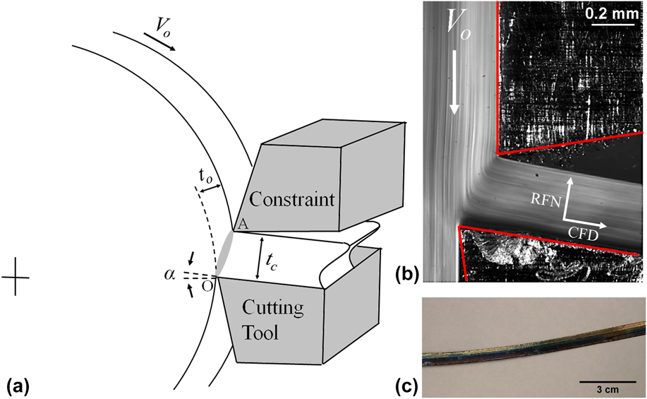
Details of the LSEM (shear) process have been described previously, but a brief summary of the principal process attributes is given here. Figure 2 shows a schematic of plane-strain LSEM in which a sharp, wedge-shaped cutting tool engages a rotating workpiece (WP) at a preset depth (t o). The interaction between the tool and WP produces a chip extrudate (sheet) by intense shear along a narrow (∼100 µm thick) deformation zone, commonly idealized as a single shear plane [plane OA, Fig. 2(a)]. Reference Efe, Moscoso, Trumble, Dale Compton and Chandrasekar12 The process of metal removal imposes large shear strains in the extrudate material. The confinement of material flow by a secondary die (constraint) placed above the primary tool, defines the geometry for the sheet with final thickness (t c). This confinement of the deformation allows for extrusion of continuous sheet by suppressing localized flow (i.e., segmentation and shear banding), particularly important in metals of limited workability like Fe–Si. Additional details on the unique capability of LSEM to overcome the poor workability limitation of high-Si by enhancing hydrostatic pressure, and temperature via adiabatic heating, in the deformation zone can be found in Ref. [Reference Kustas, Sagapuram, Trumble and Chandrasekar13].
Details of plane-strain LSEM: (a) schematic, (b) side view of material flow during sheet formation with rake face normal (RFN) and chip flow direction (CFD) axes, and (c) example Fe–Si sheet.
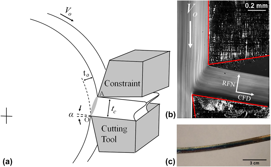
The distance between the constraint and cutting tool is controlled a priori and defines the chip thickness ratio λ = t c/t o. The LSEM process is best described as simultaneous cutting-extrusion, with the extrudate sheet subjected to a large strain (>1) that is determined primarily by λ. A side-view of the material flow based on high-speed imaging that highlights the confined shear is shown in Fig. 2(b), and a section of a continuous Fe–Si sheet sample is shown in Fig. 2(c).
The strain and deformation path (texture) can be varied in this processing independent of the sheet thickness (t c). The control parameters are λ and the tool rake angle, α, enabling a range of microstructures and predictable shear textures in Fe–Si sheet, which are not achievable by rolling. Reference Kustas, Sagapuram, Trumble and Chandrasekar13
The ability to process alloys of low workability by LSEM stems from the fact that hydrostatic pressures in the deformation zone can be adjusted to be much higher than in rolling, along with sufficiently high deformation temperatures due to confinement of the flow (in situ deformation-induced heating). Reference Efe, Moscoso, Trumble, Dale Compton and Chandrasekar12,Reference Kustas, Sagapuram, Trumble and Chandrasekar13 These factors allow also for important control of the sheet microstructure by dynamic processes (e.g., recrystallization), which can be further enhanced by workpiece heating (T o) prior to cutting. Dynamic recrystallization is particularly significant and useful in LSEM of Fe alloys, which traditionally require many passes of rolling at high temperatures to accomplish equivalent microstructural modifications. Thus, continuous sheet of high-silicon Fe alloy can be produced in a single deformation step with dynamically annealed structures, and a range of shear textures. This approach helps transcend the current limitations in rolling of high-silicon Fe sheet.
III. EXPERIMENTAL
A. Specimen preparation
The starting Fe–Si material for the deformation processing experiments was a commercial hot-rolled plate from Scientific Alloys, Inc. with a nominal composition of 4 wt% Si. The full composition provided by the manufacturer was, in wt%: 3.83 Si, 0.028 C, 0.018 P, 0.015 S, 0.006 Al, balance Fe. For the shear-based LSEM process, a single experimental condition was analyzed at
 $\bar \varepsilon$
= 1.2, (λ = 1.5, α = 5°), T
o = 25 °C, and V
o = 0.5 m/s. The resultant sheet was 3 mm wide with a thickness (t
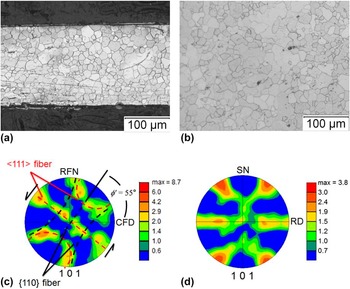
c) of 0.25 mm. A rolled sheet was also prepared from the same alloy by warm rolling at 300 °C to a similar strain as the LSEM condition. This sample had a width of 4.8 mm and thickness of 0.63 mm. Following the deformation processing, both the LSEM and rolled sheet specimens were given a recrystallization annealing treatment at T = 700 °C for 30 min to develop an equiaxed grain size d ∼25 µm. The resultant microstructures and textures of the two specimens after the annealing are shown in Fig. 3.
Microstructure and texture in the Fe–4 wt% Si sheet: (a) and (b): LSEM and rolled sheet microstructure, respectively; (c) and (d): crystallographic texture of the LSEM and rolled sheet, respectively. Note that the simple shear texture of LSEM is tilted with respect to the sample axes by 55°, unlike the rolling texture. The degree of tilt (orientation) of the simple shear texture can be controlled in the LSEM.

For both the LSEM and rolling conditions, the annealing treatment resulted in similar equiaxed grain size d = 20–30 µm [Figs. 3(a) and 3(b)]. The texture measurements [(101) pole figures, Figs. 3(c) and 3(d)] showed that each sample possesses fundamentally different crystallographic textures. The LSEM produces a simple shear texture, characterized by two partial inclined {110} and 〈111〉 fibers, highlighted on the (101) pole figure for reference. The two characteristic fibers represent rotations about the (110) crystallographic plane, which is parallel to the shear plane, and the 〈111〉 crystallographic direction, which is aligned with the shear direction. This inclined shear texture is unique compared to the measured γ (〈111〉//normal direction) and α (〈110〉//rolling direction) texture fibers of the rolled sheet [Fig. 3(d)]. Details of the shear textures from LSEM have been reported previously. Reference Kustas, Sagapuram, Trumble and Chandrasekar13,Reference Kustas, Sagapuram, Chandrasekar and Trumble14 The angle by which these fibers are inclined relative to the sheet length (chip flow direction, CFD), designated as ϕʹ, can be measured directly on the pole figure; in this case ϕʹ = 55°. Such an orientation is consistent with the shear plane model predictions for the LSEM, where a near one-to-one correspondence between expected shear plane angle and measured texture orientation has been observed. Reference Kustas, Sagapuram, Trumble and Chandrasekar13 Noteworthy is the presence of a shear texture despite a fully recrystallized microstructure, which is believed to result from continuous-type recrystallization mechanisms, different than the discontinuous recrystallization of rolled sheet. Reference Kustas, Sagapuram, Trumble and Chandrasekar13,Reference Humphreys15,Reference Jazaeri and Humphreys16
Magnetic properties were measured in the LSEM and rolled sheet after the annealing. They were also measured on a specimen from a non-grain-oriented (NGO) commercial sheet of thickness 0.27 mm and width 5 mm with trade name DI-MAX® HF-10X (NGO), supplied by AK Steel, Middletown, OH. The NGO sheet has a typical specification of 3.3 wt% Si with 0.9 wt% Al and exhibited a grain size d of 150 μm.
B. Magnetic properties
Magnetic properties of Fe–Si alloy sheet have been extensively characterized and methods to measure these properties have been thoroughly standardized. Reference Fiorillo17 The most common method to characterize commercial rolled sheets is through the Epstein test, in which multiple sheet segments are stacked into a frame with overlapping corners. Reference Fiorillo17,Reference Sievert and Ahlers18 This method, however, requires wider sheet (30 mm minimum) than is currently available by the laboratory LSEM processing. Consequentially, an alternative approach was taken for the smaller width, single sheet specimens.
Quasistatic hysteresis loops from single sheet specimens were measured at Magnet-Physics, Inc. in Fishers, IN using an IEC 60404-4 standard closed-circuit permeameter (Remagraph®C). Samples were lightly clamped within the measuring yokes and the polarization (J) was measured using J-compensated surrounding coils. In reporting the magnetization, polarization J was converted to induction B using
 $B = {\mu _{\rm{o}}}H + J,$
where
 ${\mu _{\rm{o}}}$
is the permeability of vacuum. Magnetic properties, including maximum relative permeability (µmax), induction at H = 60 kA/m (B
60), coercivity (H
c), and hysteresis loss (W) were determined from the measured hysteresis loops.
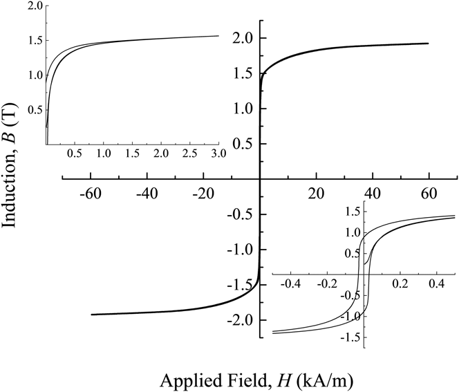
Sheet specimens with a minimum cross-sectional area of 0.3 mm2 and length of ∼92 mm were analyzed. Prior to the measurements, the oxide scale resulting from the annealing was removed from the sheet surfaces by fine grinding using 600-800 grit SiC abrasive paper followed by pickling in a 1:5 nitric acid-ethanol solution for 3–5 min. For the NGO sheet, sections of bulk commercial sheets were cut and given a manufacturer-recommended stress relief anneal in a box furnace at 800 °C for 5 min prior to the oxide removal. Sample properties were gathered along the longitudinal directions, corresponding to the chip flow direction (CFD) for LSEM and rolling direction (RD) for rolling, respectively. Hysteresis loops were measured using an applied H field up to ±60 kA/m at room temperature. The rate of magnetization was controlled such that hysteresis loops were generated in ∼1 min so as to maintain a constant change in induction with time. The applied field was obtained using a C-shaped potential coil directly attached to the specimen surface. As an example, a B–H hysteresis loop measured for the commercial NGO electrical steel sheet from AK Steel is shown in Fig. 4.
Hysteresis loop for the AK Steel NGO sample: (left) portion of the right quadrant, (middle) full hysteresis loop, (right) 500 A/m zoomed hysteresis loop. Note, the loop shown here includes the virgin magnetization curve, from which maximum relative permeability is calculated.

The B–H hysteresis loop for the commercial NGO specimen exhibited a magnetically soft response, as expected of ferromagnetic materials like Fe–Si, which terminated at B 60 = 1.92 T. High B values were obtained with a relatively small applied H field (left inset), indicative of high permeability and a narrow hysteresis loop width (right inset), yielding low coercivity (H c) and hysteresis loss (W). Analysis revealed that µmax was 10,900 for this condition, which is nearly identical to the value of 11,000 usually obtained from the Epstein frame for the same alloy sheet product. 19,20 This was taken as confirming that the present characterization process yields accurate magnetic properties.
IV. RESULTS AND DISCUSSION
A. Comparison of LSEM and rolled sheet
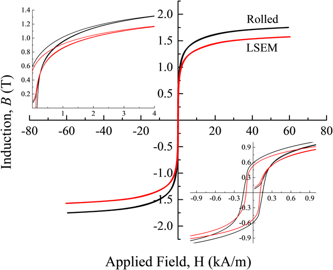
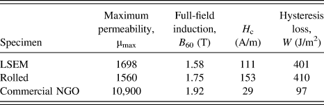
Full-field view of the B–H hysteresis loops for the LSEM and rolled specimens of the 4 wt% Si alloy are shown in Fig. 5. As expected, samples revealed soft magnetic behavior with generally narrow hysteresis loop widths. Furthermore, high B values were achieved at relatively small H fields, indicative of fairly high permeability. Loops appeared to overlap closely with one another, indicating properties were not significantly different. Maximum relative permeability, full-field induction (at H = 60 kA/m), coercivity and hysteresis loss obtained from these loops are listed in Table I.
Hysteresis loops for the experimental sheet processed by simple shear (thinner red loop) and rolling (wider black loop) deformation: (left) portion of the right quadrant, (middle) full hysteresis loops, (right) 1 kA/m zoomed hysteresis loops. Note that the loops shown here include the virgin magnetization curve, from which maximum relative permeability was calculated.

Summary of magnetic properties for the LSEM and rolled Fe–4 wt% Si alloy. For comparison, the commercial NGO sheet data is also provided.

The upper left inset in Fig. 5 is a portion of the hysteresis loop at high applied H fields, where the LSEM condition is shown to require larger H fields to achieve the same B values. However, in spite of this, analysis of the maximum permeability revealed that the LSEM condition possessed a somewhat larger maximum permeability, µmax = 1698, than the rolled condition, µmax = 1560, as measured from the virgin magnetization curve. At the maximum applied H field, both samples exhibited large induction, with B 60 = 1.58 T for the shear-textured sheet and B 60 = 1.75 T for the rolled sheet. In the lower right inset, the loops are shown near the origin of the B–H plot to detail the coercivity, where values were significantly smaller for the LSEM sheet, H c = 111 kA/m, than for the rolled specimen, H c = 153 kA/m. The coercivity differences, coupled with the lower B 60 values for LSEM, led to similar hysteresis loss, with W = 401 J/m3 and W = 410 J/m3 for the LSEM and rolled conditions, respectively.
These preliminary measurements showed that, overall, the differences in the magnetic properties between the LSEM and rolled Fe–4 wt% Si specimens were minor. This suggests that the shear process did not develop textures that contain a particularly high degree of anisotropy along the sheet length compared to the conventional rolling textures. However, of particular note, the properties of the shear-textured Fe–Si specimen were in general better than those of the rolled sheet, with higher maximum permeability, lower coercivity, and lower hysteresis loss. These differences, while subtle, are impactful considering that the composition is identical and grain size nominally the same for the two processing conditions. The slightly better performance is then likely due to the texture differences in the sheets. In general, the magnetic properties of rolled sheet improve when the intensity of the γ fiber decreases. Reference PremKumar, Samajdar, Viswanathan, Singal and Seshadri4 When processed by LSEM, sheet possess a rotated (inclined) γ fiber, fundamentally different than in rolling. Therefore, the negative contribution from the γ fiber on the magnetic properties is likely reduced for the LSEM specimen, enhancing the performance.
B. Comparison with commercial sheet
When compared to the commercial NGO sheet condition, the LSEM and rolled Fe–4 wt% Si specimens exhibited significant differences in the magnetic performance (Table I). As a whole, the magnetic performance of the Fe–4 wt% Si specimens did not match the commercial NGO sheet, with lower maximum permeability (µmax) and full-field induction (B 60), in addition to higher coercivity (H c) and hysteresis loss (W). These differences can be related to the intrinsic discrepancies in the metallurgy of the specimens, which are discussed below in relation to the grain size, texture, and composition.
1. Grain size
Grain size can have particularly influential effects on the magnetic properties, with the permeability, coercivity, and hysteresis loss being most affected. Permeability values, in general, increase with increasing grain size. This effect is particularly pronounced at low applied H fields and has been documented previously for NGO electrical steel sheets. Reference PremKumar, Samajdar, Viswanathan, Singal and Seshadri4,Reference Shiozaki and Kurosaki5 Additionally, coercivity values are known to decrease with increasing grain size. When compared to the commercial NGO sheet, the LSEM and rolled Fe–4 wt% Si specimens exhibited lower permeability, higher coercivity, and higher hysteresis loss. Structurally speaking, this might be expected when considering the fine grain size of the Fe–4 wt% Si specimens (d = 20–30 µm), which is significantly smaller than the grain size (d = 150 µm) of the NGO material (Fig. 6). Much like the role of fine grains in strengthening of metals, a finer grain size corresponds to an increase in grain boundaries, which pin the motion of magnetic domain walls. Reference Arzt21 Larger grains are therefore expected to interfere less with the microscale magnetization process than finer grains, leading to higher permeability and reduced coercivity and hysteresis loss. For low-field permeability, increases of over 50% have been documented when the grain size increases from 30 to 220 µm for a given Fe–Si composition and texture. Reference Shiozaki and Kurosaki5 Additionally, coercivity has been shown to increase with grain size as 1/d. Reference Herzer22
Example microstructures of specimens for commercial NGO and LSEM sheet samples. Larger grains of the NGO sheet (left) were likely a contributing reason for this sheet’s higher permeability, lower coercivity, and lower hysteresis loss, compared to the fine grains of the LSEM sheet (right).

2. Texture
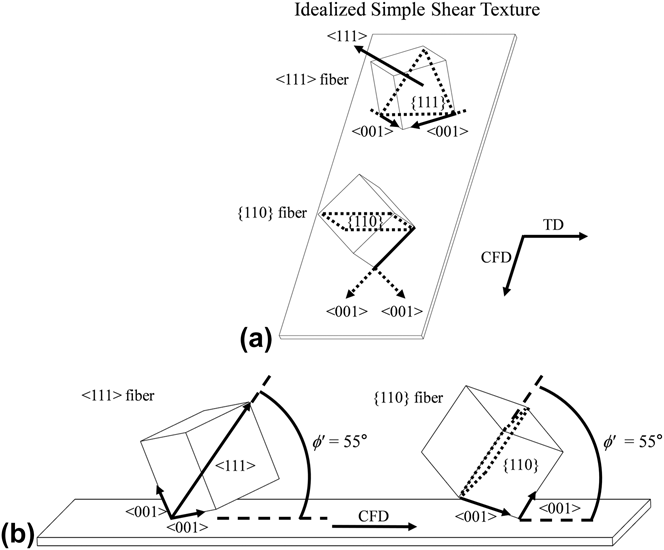
Texture heavily influences magnetic properties. For the commercial NGO sheet, textures are considered weak (near random), resulting in in-plane magnetic isotropy. A similar weak texture resulted in the rolled Fe–4 wt% Si [Fig. 3(d)]. Both of these weak rolling textures, considered as typical BCC rolling textures with γ and α fiber components, as defined in Sec. III.A, are fundamentally different than the tilted shear texture of the LSEM sheet. No previous work was found characterizing the magnetic properties of shear-textured Fe–Si sheets, due to a lack of this type of unique sheet texture. This study then represents among the first to characterize the magnetic properties of shear-textured Fe–Si sheet. The two fiber components of the shear texture shown on the pole figure in Fig. 3(c) are depicted in Fig. 7 as ideal unit cell orientations inclined at ϕʹ = 55° relative to the CFD. For the longitudinal magnetic properties of the sheet then it is important to consider the orientation of the 〈001〉 directions with respect to the applied H field.
A unit cell representation illustrating one position of the 〈111〉 and {110} simple shear fiber components for the single LSEM deformation condition at (a) an arbitrary inclination angle and (b) an inclination of 55°. Superimposed are the 〈001〉 easy magnetization directions. The 〈001〉 directions are tilted with respect to both the surface normal and sheet length.

Since these texture components are fibers (rotated about direction or plane normal), consideration of the magnetically active 〈001〉 direction orientations along the full fiber is complex and is based on the relative strengths (intensities) of the two fibers. The essential feature of this type of texture, depicted in Fig. 7, is the inclination of the 〈001〉 directions relative to the applied field direction, which depend on the shear plane angle. For the particular case in Fig. 7(b), defined by ϕʹ = 55° corresponding to the LSEM sheet in this study, the orientations of the 〈001〉 easy magnetization directions away from the direction of the applied field are 48.3° and 70.3° for the 〈111〉 fiber and 54.6° and 55° for the {110} fiber, respectively. These orientations are then expected to have a direct influence on the magnetic performance of shear-textured Fe–Si.
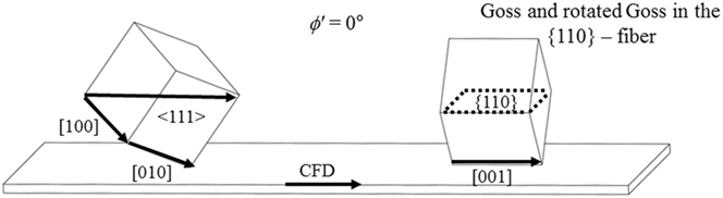
Overall, the inclined 〈001〉 directions might be considered similar to those of the NGO and rolled sheets. However, an important distinction is worth discussing. Unlike rolled sheet, the tilted orientations of the 〈001〉 directions in the LSEM sheet can be controlled in a predictable manner. Reference Kustas, Sagapuram, Trumble and Chandrasekar13 From Fig. 7, the orientation of the 〈001〉 directions with respect to the field direction is shown to vary significantly as a function of the shear plane angle for the two simple shear fibers. Consequentially, improvement of properties in shear textured Fe–Si sheet must consider both the relative volume fractions of the {110} and 〈111〉 fibers and the shear plane orientation. This is fundamentally different than for the rolled textures, where the γ fiber is generally minimized to optimize the magnetic properties. Reference PremKumar, Samajdar, Viswanathan, Singal and Seshadri4 Based on the LSEM control over textures, a shear texture could be engineered such that one component along the 〈111〉 fiber possesses two 〈001〉 directions in the plane of the LSEM sheet by selecting deformation conditions that induce a shear texture with an inclination angle of 35.3°. In the unit cell representation, this angle corresponds to the angle between [111] and its projection on (100) or [110]. An additional example of particular interest is the 〈001〉 orientation angles as the shear plane angle approaches 0° (Fig. 8). Interestingly, at this low shear plane angle, the {110} fiber in fact possesses a Goss orientation that rotates about the (110) plane, leaving a distribution of [001] directions in the plane of the sheet—a potential ‘Goss fiber’. Furthermore, previous work has shown that high temperature annealing treatments can induce preferential grain growth of regions with fiber orientations at 0°. Reference Kustas, Sagapuram, Trumble and Chandrasekar13 It is interesting to consider the resultant magnetic properties of a sheet with a simple shear texture having a 0° inclination with a large volume fraction of orientations from the {110} fiber. Perhaps sheets could be produced with nearly ideal magnetic properties for rotating applications (electrical motors) by virtue of a Goss fiber texture.
Side view of unit cell orientations for a shear plane angle, ϕʹ, of 0°: (left) the 〈111〉 fiber, (right) the {110} fiber. At this shear plane angle, a rotated Goss fiber could possibly result in a distribution of 〈001〉 directions in the plane of the sheet.

3. Composition
A brief discussion of compositional differences is also in order. The specimens tested here had similar total solute content, with the LSEM and rolled specimens containing nominally 4 wt% Si, compared to 3.3 wt% Si + 0.9 wt% Al for the NGO commercial sheet. However, significant differences in the full-field induction values were observed, with B 60 = 1.58 T, 1.75 T, and 1.92 T for the LSEM, rolled and NGO specimens, respectively. Overall, the LSEM and rolled conditions possessed lower B 60 values than the NGO sheet, in spite of similar total solute content. The primary reason for the lower B 60 values is believed to be the comparatively lower permeability, which is expected to lead to lower B values for a given applied H field. Furthermore, the Fe–4 wt% Si alloy specimens contained significantly higher alloy impurities, which are expected to negatively impact the permeability, coercivity, and hysteresis loss. Specifically, the LSEM and rolled specimens contained order of magnitude higher carbon (0.028 wt%) and sulfur (0.015 wt%) contents, compared to the NGO sheet, which contained <0.003 wt% for both interstitial elements. Due to the higher interstitial content, which has previously been noted to severely impact the magnetic properties of Fe–Si over the same range, it is perhaps not surprising that the Fe–4 wt% Si specimens exhibited a poorer magnetic performance than the high-purity commercial NGO specimens. Reference Yensen9–Reference Leak and Leak11,Reference Yensen and Ziegler23
C. Implications
Of particular importance is the demonstration of producing continuous sheet of Fe–Si from high-silicon alloys using a thermomechanical deformation process—LSEM. These sheets possessed inclined shear textures, fundamentally different from the texture in rolled sheet. Interestingly, for the same composition in a rolled condition, the LSEM sheet possessed overall improved magnetic performance, indicating that the shear process is a viable processing option to develop Fe–Si sheet with improved properties for a given silicon composition. Furthermore, controlling texture, microstructure, and silicon content of sheet via LSEM creates a potential for producing sheets with tailored magnetic properties. One particularly promising example that was recently demonstrated is the processing of continuous Fe–6.5 wt% Si sheet using simple shear deformation directly from cast ingots. Reference Kustas, Sagapuram, Trumble and Chandrasekar13 Magnetic properties are generally considered optimized at this composition and several processing methods have been attempted to realize sheet at 6.5 wt% Si with little commercial success. Therefore, the LSEM process shows potential to develop high-efficiency Fe–Si sheet for electromagnetic devices by control of silicon composition and crystallographic texture. A more in-depth study on texture and silicon effects on magnetic properties is currently underway.
V. CONCLUSIONS
-
(1) A single-step shear deformation process—large strain extrusion machining (LSEM)—was used to produce continuous sheet from Fe–4 wt% Si alloy. The unique inclined simple shear, crystallographic texture in this sheet is consistent with the imposed deformation path. But the texture is quite different from that created by rolling.
-
(2) Bulk magnetic properties were measured for the shear-textured and rolled sheet of Fe–4 wt% Si alloy using a permeameter and compared with those of a commercial NGO sheet.
-
(3) For the Fe–4 wt% Si, the shear-textured sample revealed better performance with higher maximum permeability, lower coercivity, and lower hysteresis loss. However, both specimens from the 4 wt% Si alloy were unable to achieve the optimum properties of the commercial NGO sheet. The reasons appear to be related to the finer grain size and lower alloy purity of the LSEM and rolled sheet.
-
(4) A unit cell model describing the simple shear textures of LSEM is introduced with potential implications to sheet magnetic properties. Advantageous texture components, in combination with higher silicon compositions, could potentially lead to the development of Fe–Si sheet with properties superior to those of conventional grades.
ACKNOWLEDGMENTS
This work was supported in part by NSF CMMI 1562470 and DMR 1610094, U.S. Army Research Office Award W911NF-15-1-0591 and a Purdue University Bilsland Fellowship (to AK). The authors are grateful to Reinhold M.W. Strnat of Magnet-Physics Inc. for the magnetic properties characterization.