1. Introduction
The 3-degree-of-freedom (DOF) 1T2R (T and R represent translational and rotational motions, respectively) parallel mechanisms (PMs), generating hybrid output motion, have a good application prospect in freeform surface machining, crops picking, friction stir welding, and joint rehabilitation training [Reference Dong, Liu and Yang1]. Currently, partial 1T2R PMs have been successfully put into industrial application such as A3/Z3 tool head, Tricept, Exechon, and TriVariant.
Dimensional synthesis is the critical process to realize engineering design and application of PMs, which aims at optimizing the scale parameters of mechanisms based on the performance indicators such as kinematics, dynamics, bearing capacity, and static stiffness [Reference Yang, Ye and Li2]. Some scholars have carried out a lot of research on dimensional synthesis of 1T2R PMs, among which the optimization design based on kinematic performance is the common and efficient method. Song et al. [Reference Song, Zhao, Zhao, Yan and Chen3] achieved the dimensional synthesis for 3-UPU (U is universal joint and P is prismatic joint) PM based on performance atlas. Xu et al. [Reference Xu, Tong, Wang, Ju, Yao and Zhao4] used the ideal-point method to establish a unified objective function including the maximum bearing capacity and the minimum driving branch motion range and further optimized structural parameters of 2RPU-UPR (R is revolute joint) PM applied in antenna support. Yang et al. [Reference Yang, Zhou, Deng, Duan, Dou, Zeng and Hou5] constructed the optimization model for the maximum natural frequency of 3-RPS (S is spherical joint) PM. Furthermore, the genetic algorithm (GA) was employed to solve this optimization problem. The aforementioned cases can all be attributed to single-objective extreme value optimization problem, which is not suitable for guiding engineering design and application.
For engineering applications, it is usually expected that multi-performance indices of PMs can be simultaneously excellent, but these indices often conflict with each other. To this end, the multi-objective optimization of the 1T2R PMs needed to be performed for satisfying the practical applications. In this respect, scholars proposed some methods that can achieve the multi-objective optimization. Wang et al. [Reference Wang, Xu and Guan6] utilized spatial model method to achieve multi-objective optimization of 3-PUU mechanism with the goal of optimal motion/force transmissibility and orientation capability. RUSSO et al. [Reference Matteo, Saioa, Oscar and Ceccarelli7] established the multi-objective dimensional synthesis model of 3-UPR PM with the optimization objectives of workspace, dexterity, and stiffness and ultimately obtained multiple Pareto optimal solutions. GAO et al. [Reference Gao and Zhang8] established the multi-objective optimization model for the maximum workspace, global stiffness, dexterity, and operability and then applied the multiple population GA to solve this model. Zhang et al. [Reference Zhang, Li, Ye and Yang9] used multi-objective particle swarm optimization (PSO) algorithm solve the multi-objective optimization problem for 2PUR-PSR mechanism, and then the regular workspace and global motion/force transmission index of this PM were optimized. Li et al. [Reference Li, Qu and Li10], based on error and workspace, established the multi-objective optimization model of (2PRR)-R-2RRR PM and applied non-dominated sorting genetic algorithm II (NSGA-II) to obtain multiple sets of Pareto optimal solutions.
The aforementioned studies all achieved multi-objective optimization of 1T2R PMs through intelligent algorithms, while the objective functions are not directly related to engineering requirements, and these optimized mechanisms are also not used as main structure to design more novel equipment. Therefore, this paper focuses on multi-objective optimization of the 2RPU-RPS PM for specific engineering requirement. Moreover, the optimized mechanism is taken as the execution component to design a novel multi-DOF hydraulic support test bed, which can provide a theoretical reference for solving the technical problems faced by existing test beds with single DOF.
The main contributions of this work can be summarized as follows: (1) using 2RPU-RPS mechanism as loading executive device, this paper designed a novel 5-DOF hybrid hydraulic support test bed. (2) Based on the actual requirement of loading test, the expensive constrained multi-objective optimization (ECMOP) model of 2RPU-RPS mechanism is established, which is then solved by improved multi-objective evolutionary algorithm (MOEA). (3) Combined with the optimization result, the virtual prototype of the novel 5-DOF hybrid hydraulic support test bed is designed, and its load-bearing capacity is verified through the finite element analysis.
The rest of this paper is organized as below. In Section 2, the kinematic analysis of 2RPU-RPS mechanism is carried out. The calculation methods of performance indices are presented in Section 3. In Section 4, the multi-objective optimization model is established and the solving algorithm is given. Section 5 presents the implementation of multi-objective dimensional optimization for 2RPU-RPS mechanism. In Section 6, the finite element analysis of novel 5-DOF hybrid loading test bed of hydraulic support is given.
2. Kinematic analysis of 2RPU-RPS PM
This section first described the topological structural characteristics and further established kinematic models by means of vector method. To enhance the orientation capability, the output axis of end effector on the moving platform is designed as deviating type, and its orientation is depicted through the spherical attitude angles (i.e., azimuth and tilt angles) according to Ref. [Reference Peng, Cheng, Che, Zheng and Cao11].
2.1. Architecture description of mechanism
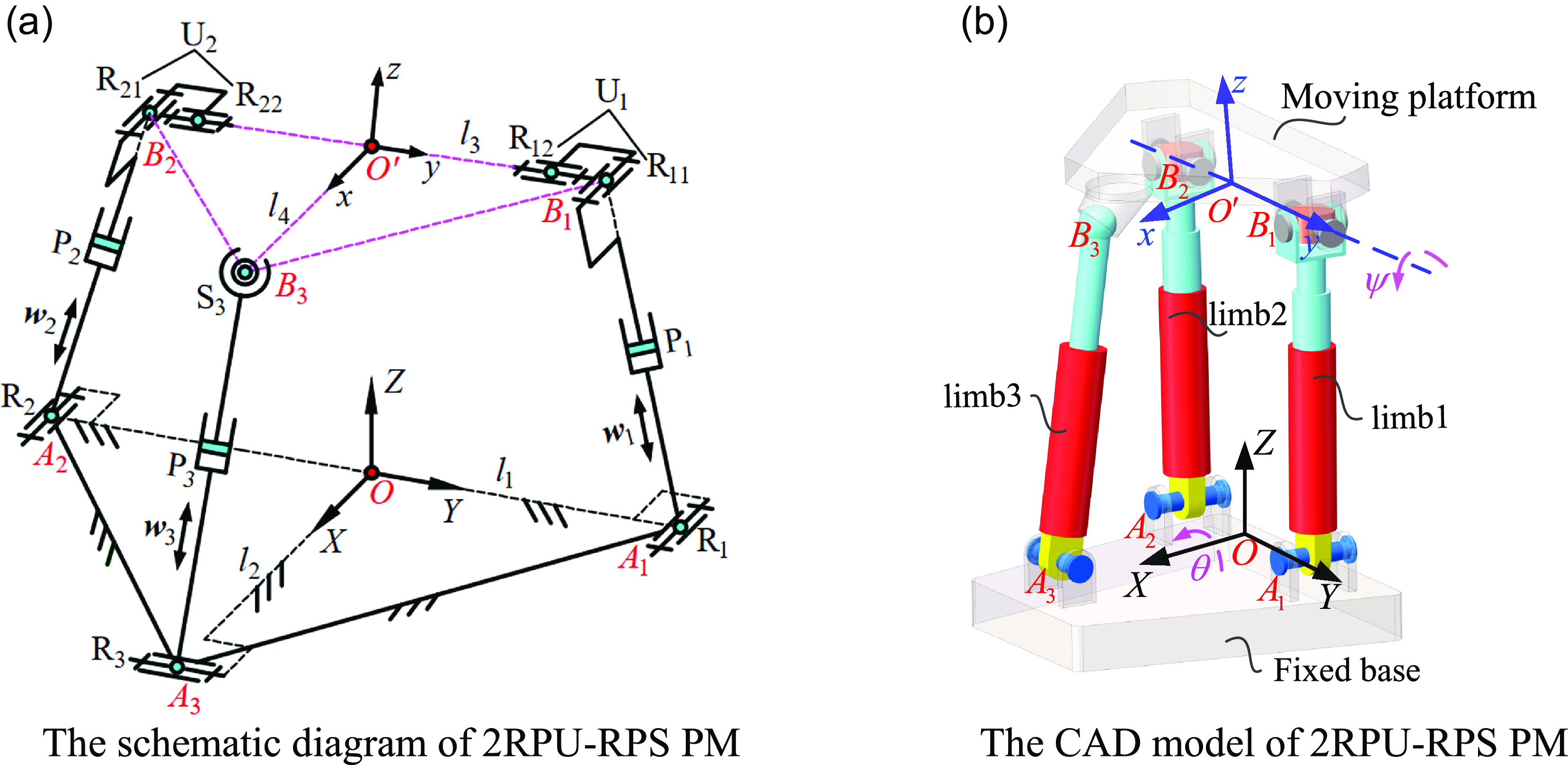
The planar symmetric 2RPU-RPS PM is composed of a fixed base, a moving platform, and three branches, whose schematic diagram and CAD model are presented in Figure 1. For ease of description, R1P1U1 and R2P2U2 chains are marked as limb1 and limb2, and their topological structure can be represented as {-R1-P1-R11⊥R12} and {-R2-P2-R21⊥R22}, respectively. The topological structure of limb3 is {-R3-P3-S3-}. As shown in Figure 1(a), the fixed base and the moving platform are both designed as isosceles triangle, that is, △A
1
A
2
A
3 and △B
1
B
2
B
3. Points A
i
(i represents the order of each branch, i = 1, 2, 3) are centers of revolute joints R
i
, and points B
i
are centers of universal joints U1 and U2 and spherical joint S3. O and O
′ are the midpoints of bottom edges A
1
A
2 and B
1
B
2, and OA
3 and O
′
B
3 are the height of △A
1
A
2
A
3 and △B
1
B
2
B
3. Additionally, the prismatic joint P
i
of each branch is the active joint, and its driving displacement and direction vectors are
 $q_{i}$
and
 $\boldsymbol{w}_{i}$
. The structural parameters of this mechanism are as follows.
 $\overline{A_{1}A_{2}}=2\mathrm{l}_{1}, \overline{\mathit{OA}_{3}}=l_{2}, \overline{B_{1}B_{2}}=2\mathrm{l}_{3}, \overline{O^{\prime}B_{3}}=l_{4}$
. In Figure 1(b), θ and
 $\psi$
represent output Euler angles of the moving platform.
2RPU-RPS parallel mechanism. (a) The schematic diagram of 2RPU-RPS PM. (b) The CAD model of 2RPU-RPS PM.

The global coordinate frame {f} : O-XYZ is established on the fixed base A
1
A
2
A
3, where X axis is along OA
3, Y axis is along OA
1, and Z axis can be directly determined by right-hand rule. Then set
 $\hat{\boldsymbol{x}}, \hat{\boldsymbol{y}}$
and
 $\hat{\boldsymbol{z}}$
to be the unit vectors of each coordinate axis in the {f}. Similarly, the local coordinate frame {m} : O
′-xyz is attached to the moving platform B
1
B
2
B
3, in which x axis is collinear with O′B
3, y axis is collinear with O′B
1, and z axis is perpendicular to the plane of the moving platform according to right-hand rule. Then the unit vectors of axes in {m} are
 $\widehat{\boldsymbol{x}^{\prime}}, \widehat{\boldsymbol{y}^{\prime}}$
and
 $\widehat{\boldsymbol{z}^{\prime}}$
, respectively.
Based on the established coordinate frames, the whole structure of discussed mechanism is semi-symmetric about XOZ plane. The assembly geometric relationship among each kinematic joint in the 2RPU-RPS PM can be described as follows. Revolute joints R1 and R2 are attached on the fixed base, and their axes are parallel to X axis. Universal joint U1 is formed by vertical intersection of revolute joints R11 and R12, and then R11 and R12 are, respectively, connected to the end of limb1 and the moving platform. The composition of universal joint U2 is identical to U1. In the two universal joints U1 and U2, the axes of R11 and R21 are both parallel x axis, and the axes of R12 and R22 are coaxially assembled on the y axis. Hence, limb1 and limb2 are always located in the YOZ plane. In addition, limb3 is connected to the fixed base and the moving platform through revolute joint R3 and spherical joint S3, and axis of R3 is always perpendicular to R1 and R2. Therefore, limb3 is always located in the XOZ plane. Moreover, there exist following geometric relationships in the initial pose of this mechanism, that is, x is parallel to X, and points O and O′ are collinear.
2.2. Analysis for the inverse displacement
According to the conclusion in Ref. [Reference Zhao, Li, Li, Pang, Zhang and Kang12], the DOF of 2RPU-RPS mechanism is 2R1T, that is, one rotation is around X axis, the other is around y axis, and the translation is along Z axis. Suppose O′
to be the reference point of the end effector, and its coordinate vector in the coordinate system {f} to be
P
= (X
P
, Y
P
, Z
P
)T. Hence, the inverse displacement of this mechanism can be expressed as solving the driving displacement of each branch
 $q_{i}$
(i = 1, 2, 3) with the structural parameters (l
1, l
2, l
3, l
4) and the end output pose (θ,
 $\psi$
, Z
P
).
The coordinate vector of point A i (i = 1, 2, 3) in the {f} can be written as:
 \begin{align} \left\{\begin{array}{l} \boldsymbol{A}_{1}=\left(0,l_{1},0\right)^{\mathrm{T}} \\[3pt] \boldsymbol{A}_{2}=\left(0,-l_{1},0\right)^{\mathrm{T}}.\\[3pt] \boldsymbol{A}_{3}=\left(l_{2},0,0\right)^{\mathrm{T}} \end{array}\right. \end{align}
The coordinate vector of point B i (i = 1, 2, 3) in the {m} can be written as:
 \begin{align} \left\{\begin{array}{l} \boldsymbol{b}_{1}=\left(0,l_{3},0\right)^{\mathrm{T}} \\[3pt] \boldsymbol{b}_{2}=\left(0,-l_{3},0\right)^{\mathrm{T}}.\\ [3pt] \boldsymbol{b}_{3}=\left(l_{4},0,0\right)^{\mathrm{T}} \end{array}\right. \end{align}
The X-Y-Z type Euler angles (θ,
 $\psi$
, 0) can be directly used to depict the orientation of the moving platform, since the discussed mechanism has two rotational DOFs that do not rotate around its own axis. Therefore, we can obtain the orientation matrix of the coordinate system {m} relative to the {f}, that is,
 \begin{align} \boldsymbol{M}=\mathrm{Rot}\left(X,\theta \right)\mathrm{Rot}\left(y,\psi \right)=\left(\begin{array}{c@{\quad}c@{\quad}c} \cos \psi & 0 & \sin \psi \\[3pt] \sin \theta \sin \psi & \cos \theta & -\sin \theta \cos \psi \\[3pt] -\cos \theta \sin \psi & \sin \theta & \cos \theta \cos \psi \end{array}\right). \end{align}
The parasitic motion along X axis, denoted as X P , is equal to 0, since points B 1, B 2, and O ′ are always located in YOZ plane. According to coordinate transmission rule, the coordinate vector of point B i (i = 1, 2, 3) in the {f} can be expressed as:
 \begin{align} \boldsymbol{B}_{i}=\left(X_{{B_{i}}},Y_{{B_{i}}},Z_{{B_{i}}}\right)^{\mathrm{T}}=\boldsymbol{P}+\boldsymbol{M}\boldsymbol{b}_{i}\left(i=1,2,3\right). \end{align}
Note that since point B
3 is always in XOZ plane, the translation along Y axis of this point is equal to 0, that is,
 $Y_{{B_{3}}}=0$
. From Eq. (4), the parasitic motion along Y axis of the moving platform can be formulated as:
 \begin{align} Y_{P}=-l_{4}\sin \theta \sin \psi .\end{align}
Eq. (5) indicates that 2RPU-RPS PM only has parasitic motion along the Y axis, which can to some extent reduce the complexity of its position calibration, trajectory planning, and motion control.
According to constraint of rod length, the calculation model of inverse displacement is obtained as follows:
 \begin{align} q_{i}=\left\| \boldsymbol{B}_{i}-\boldsymbol{A}_{i}\right\| \left(i=1,2,3\right). \end{align}
2.3. Orientation depiction for offset output axis
Due to the absence of rotation around its own axis, the azimuth angle
 $\zeta$
and tilt angle
 $\xi$
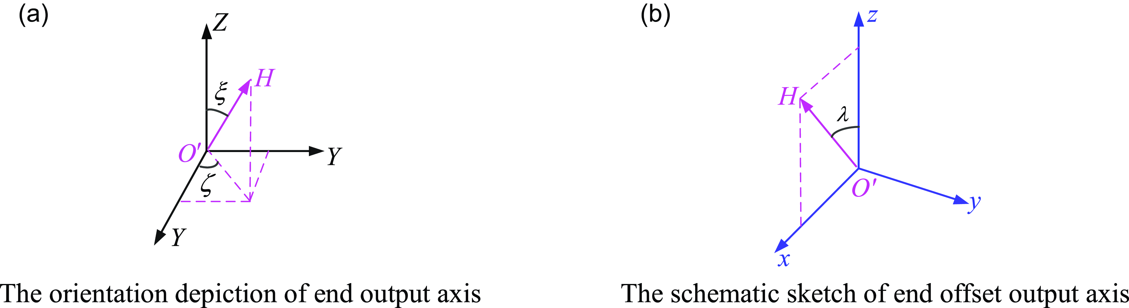
(seen in Figure 2(a)) can be used to depict the orientation of end output axis O′H of 2RPU-RPS mechanism. Upon this foundation, the orientation capability of mechanism can be defined as the maximum tilt angle that the output axis O′H can achieve under any azimuth angle. The workspace of 2RPU-RPS mechanism is symmetric about XOZ plane owing to its semi-symmetric topological structure characteristic. Consequently, the tilt angle
 $\xi$
of end output axis is also symmetric about XOZ plane but asymmetric about YOZ plane, which to some extent limits the orientation capability of the end effector. In other words, the tilt angle of the output axis at certain azimuth angles may be very small. To improve orientation capability of the whole mechanism, we designed end output axis O
′
H of this mechanism as deviating type, that is, there exists an offset angle
 $\lambda$
between output axis O′H and moving platform normal O
′
z (seen in Figure 2(b)). Notice that
 $\lambda$
is also located in XOZ plane.
The end offset output axis of 2RPU-RPS mechanism. (a) The orientation depiction of end output axis. (b) The schematic sketch of end offset output axis.

Figure 2(a) presents the situation of describing the orientation of output axis O′H in the T&T angles (
 $\zeta, \xi$
). In this figure, the unit vector of O′H can be further written as:
 \begin{align} \boldsymbol{n}_{O^{\prime}H}=\left(\sin \xi \cos \zeta, \sin \xi \sin \zeta, \cos \xi \right)^{\mathrm{T}} .\end{align}
According to Figure 2(b), the unit vector of end output axis O ′ H in the coordinate system {f} can be written as:
 \begin{align} \boldsymbol{n}_{O^{\prime}H}=\boldsymbol{M}\!\left(\sin \lambda \mathrm{,}0\mathrm{,}\cos \lambda \right)^{\mathrm{T}}=\left(\begin{array}{c} \cos \psi \sin \lambda +\sin \psi \cos \lambda \\[3pt] \sin \theta \sin \psi \sin \lambda -\sin \theta \cos \psi \cos \lambda \\[3pt] -\cos \theta \sin \psi \sin \lambda +\cos \theta \cos \psi \cos \lambda \end{array}\right). \end{align}
Comparing Eqs. (7)–(8), we can obtain
 \begin{align} \left\{\begin{array}{c} \psi =\arcsin \left(\sin \xi \cos \zeta \right)-\lambda \\[3pt] \theta =\arctan 2\left(-\dfrac{\sin \xi \sin \zeta }{\cos \!\left(\psi +\lambda \right)},\dfrac{\cos \xi }{\cos \! \left(\psi +\lambda \right)}\right) \end{array}\,\,\left(\left| \psi +\lambda \right| \lt {\unicode[Arial]{x03C0}} /2\right)\right. \end{align}
Eq. (9) is essentially a functional relationship between orientation parameters of output axis and Euler angles of moving platform. Obviously, there are two solutions to Euler angle
 $\psi$
, and the one, meeting condition
 $| \psi +\lambda | \lt {\unicode[Arial]{x03C0}} /2$
, is selected based on practical requirement.
3. Kinematic performance analysis of 2RPU-RPS PM
In this section, the analytical formulae of good transmission orientation workspace (GTOW), global transmission index (GTI), and transmission fluctuation index (TFI) are given to evaluate the overall kinematic performance of 2RPU-RPS PM.
3.1. Motion/force transmission performance analysis
From Figure 1(a), the twist screw of limb1 in the coordinate system {f} are
 \begin{align} \left\{\begin{array}{l} \boldsymbol{\$ }_{11}=\left(\hat{\boldsymbol{x}}\mathrm{,}\,\mathbf{0}_{3\times 1}^{\mathrm{T}}\right)\\[5pt] \boldsymbol{\$ }_{12}=\left(\mathbf{0}_{3\times 1}^{\mathrm{T}}\mathrm{,}\,\boldsymbol{w}_{1}\right)\\[5pt] \boldsymbol{\$ }_{13}=\left(\widehat{\boldsymbol{x}^{\prime}}\mathrm{,}\,\boldsymbol{r}_{{\mathit{OB}_{1}}}\times \widehat{\boldsymbol{x}^{\prime}}\right)\\[5pt] \boldsymbol{\$ }_{13}=\left(\widehat{\boldsymbol{y}^{\prime}}\mathrm{,}\,\boldsymbol{r}_{{\mathit{OB}_{1}}}\times \widehat{\boldsymbol{y}^{\prime}}\right) \end{array}\right., \end{align}
where
 $\mathbf{0}_{3\times 1}$
is the zero column of three elements, and
 $\boldsymbol{r}_{{\mathit{OB}_{1}}}$
is the position vector of point B
1 in the {f}.
For lower DOF limb in PM, each constrained wrench screw (CWS) is reciprocal with all twist screws. Hence, the CWSs can be obtained by solving reciprocal screw of Eq. (10), that is,
 \begin{align} \left\{\begin{array}{l} \boldsymbol{\$ }_{11}^{\mathrm{r}}=\left(\hat{\boldsymbol{x}},\boldsymbol{r}_{{\mathit{OB}_{1}}}\times \hat{\boldsymbol{x}}\right)\\[5pt] \boldsymbol{\$ }_{12}^{\mathrm{r}}=\left(\mathbf{0}_{3\times 1}^{\mathrm{T}},\widehat{\boldsymbol{z}^{\prime}}\right) \end{array}\right. \end{align}
Eq. (11) indicates that limb1 imposes two constraints on the moving platform, one is a pure force passing through point B 1 and parallel to the X axis, and the other is a constraint couple perpendicular to the plane formed by the two rotation axes of U1 joint. Due to the identical topological structure of limb1 and limb2, the CWS generated by them are also identical.
Similarly, the twist screw of limb 3 in the {f} can be written as:
 \begin{align} \left\{\begin{array}{l} \boldsymbol{\$ }_{31}=\left(\hat{\boldsymbol{x}},\mathbf{0}_{3\times 1}^{\mathrm{T}}\right)\\[5pt] \boldsymbol{\$ }_{32}=\left(\mathbf{0}_{3\times 1}^{\mathrm{T}},\boldsymbol{w}_{3}\right)\\[5pt] \boldsymbol{\$ }_{33}=\left(\hat{\boldsymbol{x}},\boldsymbol{r}_{{\mathit{OB}_{3}}}\times \hat{\boldsymbol{x}}\right)\\[5pt] \boldsymbol{\$ }_{34}=\left(\hat{\boldsymbol{y}},\boldsymbol{r}_{{\mathit{OB}_{3}}}\times \hat{\boldsymbol{y}}\right)\\[5pt] \boldsymbol{\$ }_{35}=\left(\hat{\boldsymbol{z}},\boldsymbol{r}_{{\mathit{OB}_{3}}}\times \hat{\boldsymbol{z}}\right) \end{array}\right., \end{align}
where
 $\boldsymbol{r}_{{\mathit{OB}_{3}}}$
is the position vector of point B
3 in the {f}.
The corresponding reciprocal screw of limb3 can be expressed as:
 \begin{align} \boldsymbol{\$ }_{31}^{r}=\left(\hat{\boldsymbol{y}},\boldsymbol{r}_{{\mathit{OB}_{3}}}\times \hat{\boldsymbol{y}}\right). \end{align}
It can be seen from Eq. (13) that the constraint force generated in limb 3 passes through point B 3 and are parallel to Y axis.
Substituting Eq. (4) into Eqs. (11) and (13), we can further obtained the whole CWS of 2RPS-RPU PM as follows:
 \begin{align} \left\{\begin{array}{l} \boldsymbol{\$ }_{\mathrm{CWS}}^{1}=\left(1,0,0;\ 0,Z_{P}+l_{3}\sin \theta, -\left(Y_{P}+l_{3}\cos \theta \right)\right)\\[3pt] \boldsymbol{\$ }_{\mathrm{CWS}}^{2}=\left(0,1,0;\ -\left(Z_{P}-l_{4}\sin \theta \right),0,l_{4}\cos \psi \right)\\[3pt] \boldsymbol{\$ }_{\mathrm{CWS}}^{3}=\left(0,0,0;\ 0,-\sin \theta, \cos \theta \right) \end{array}\right. \end{align}
According to the conclusion in Ref. [Reference Chen, Xie and Liu13], the transmission wrench screw (TWS) in each branch chain is an additional CWS after rigidizing the active joint P i (i = 1, 2, 3). Hence, the TWS generated in each driving chain of 2RPU-RPS mechanism is a pure force, which crosses point A i along the w i direction, that is,
 \begin{align} \boldsymbol{\$ }_{\mathrm{TWS}}^{i}=\left(\boldsymbol{w}_{i}^{\mathrm{T}},\left(\boldsymbol{A}_{i}\times \boldsymbol{w}_{i}\right)^{\mathrm{T}}\right)\left(i=1,2,3\right). \end{align}
Analyzing motion/force transmissibility involves calculating input transmission screw (ITS) and output transmission screw (OTS). The prismatic pair P in each branch chain is the active joint, whose corresponding twist screw is denoted as ITS, that is,
 \begin{align} \boldsymbol{\$ }_{\mathrm{ITS}}^{i}=\left(\mathbf{0}_{3\times 1}^{\mathrm{T}},\boldsymbol{w}_{i}^{\mathrm{T}}\right)^{\mathrm{T}}\left(i=1,2,3\right). \end{align}
The OTS in i-th limb, denoted as
 $\boldsymbol{\$ }_{\mathrm{OTS}}^{i}$
, can be defined as an instantaneous OTS at the end of the corresponding single DOF spatial linkage mechanism after locking the driving pairs of the other two branch chains except for i-th branch chain, and then the calculation method and steps of
 $\boldsymbol{\$ }_{\mathrm{OTS}}^{i}$
has been elaborated in Ref. [Reference Che, Wang and He14].
The input transmission index (ITI) of i-th limb, indicating the motion/force transmission efficiency from ITS to related TWS, can be expressed as
 \begin{align} \eta _{\mathrm{ITI}}^{i}=\frac{\left| \boldsymbol{\$ }_{\mathrm{ITS}}^{i}\circ \boldsymbol{\$ }_{\mathrm{TWS}}^{i}\right| }{\left| \boldsymbol{\$ }_{\mathrm{ITS}}^{i}\circ \boldsymbol{\$ }_{\mathrm{TWS}}^{i}\right| _{\max }}\left(i=1,2,3\right), \end{align}
where sign “
 $\circ$
” is reciprocal operator. Substituting Eqs. (15)∼(16) into Eq. (17), we can obtain
 $\eta _{\mathrm{ITI}}^{i}\equiv 1(i=1,2,3)$
.
Eq. (17) further indicates that the input transmission singularity will not occur in 2RPU-RPS mechanism.
Similarly, the output transmission index (OTI) of each limb represents the transmission efficiency form TWS to corresponding OTS, whose analytical formulae is
 \begin{align} \eta _{\mathrm{OTI}}^{i}=\frac{\left| \boldsymbol{\$ }_{\mathrm{OTS}}^{i}\circ \boldsymbol{\$ }_{\mathrm{TWS}}^{i}\right| }{\left| \boldsymbol{\$ }_{\mathrm{OTS}}^{i}\circ \boldsymbol{\$ }_{\mathrm{TWS}}^{i}\right| _{\max }}\left(i=1,2,3\right), \end{align}
where
 $\eta _{\mathrm{OTI}}^{i}\in [0,1]$
, and if
 $\eta _{\mathrm{OTI}}^{i}$
is equal or close to 0, the output transmission singularity occurs.
Subsequently, it is necessary to simultaneously consider input and output transmissibility when evaluating the whole motion/force transmission performance. Thereby, the local transmission index (LTI) is defined as below
 \begin{align} \eta _{\mathrm{LTI}}=\min _{i=1,2,3}\left\{\eta _{\mathrm{ITI}}^{i},\eta _{\mathrm{OTI}}^{i}\right\}=\min _{i=1,2,3}\left\{\eta _{\mathrm{OTI}}^{i}\right\} .\end{align}
As can be seen from Eq. (19),
 $\eta _{\mathrm{LTI}}$
is also dimensionless and ranges from 0 to 1. The closer to 1, the better motion/force transmission performance. Based on aforementioned solving process of
 $\eta _{\mathrm{LTI}}$
, LTI can only evaluate the motion/force transmissibility of 2RPU-RPS PM at a certain instantaneous position and orientation. In other words, there is a functional relationship between
 $\eta _{\mathrm{LTI}}$
and end output pose parameters of this mechanism, that is,
 \begin{align} \eta _{\mathrm{LTI}}=\eta _{\mathrm{LTI}}\left(Z_{\mathrm{P}},\zeta, \xi \right). \end{align}
3.2. Performance analysis of workspace
For 2RPU-RPS mechanism, its workspace can be defined as a point set formed by all reachable position and orientation of reference point O
′ of the moving platform. Moreover, the allowable index
 $[\eta ]$
is set as 0.7, which can ensure that the parallel loading mechanism has a good transmissibility and is far away from singular positions.
Owing to the minimal impact on the transmission performance indices [Reference Xie, Liu and Li15], the section height of workspace Z
P
can be preset to a fixed value. At this point,
 $\eta _{\mathrm{LTI}}$
is degenerated into a binary function regarding orientation parameters, that is,
 $\eta _{\mathrm{LTI}}=\eta _{\mathrm{LTI}}(\zeta, \xi )$
. On this basis, the workspace composed of all orientation satisfying Eq. (21) can be defined as GTOW with fixed section, known as
 $\Omega _{\text{GTOW}}$
:
 \begin{align} \eta _{\mathrm{LTI}}=\eta _{\mathrm{LTI}}\left(\zeta, \xi \right)\geq \left[\eta \right]=0.7 .\end{align}
Taking the point
 $(\zeta, \xi )=(0,0)$
as center, we plot the maximum inscribed circle (MIC) for GTOW, which is then called regular good transmission orientation workspace (RTOW), denoted as
 $\Omega _{\,\text{RTOW}}$
. The radius
 $\xi _{\mathrm{R}}$
of RTOW can directly depict the orientation capability of 2RPU-RPS mechanism, which is written as:
 \begin{align} \xi _{\mathrm{R}}=\min \left\{\xi \mathit{|}\eta _{\mathrm{LTI}}\left(\zeta, \xi \right)=\left[\eta \right],\forall \zeta \in \left[0,2\pi \right)\right\} .\end{align}
The essence of
 $\xi _{\mathrm{R}}$
is the orientation capability of the end output axis on the moving platform, and the larger its value, the better the orientation capability of 2RPU-RPS mechanism, that is, the maximum tilt angle that can be achieved under any azimuth angle is larger.
For quantitatively analyzing and evaluating
 $\Omega _{\,\text{RTOW}}$
, the GTI and TFI are further introduced, whose analytical formulae are as follows:
 \begin{align} \eta _{\mathrm{GTI}}=\frac{\int _{0}^{2{\unicode[Arial]{x03C0}} }\int _{0}^{\xi _{\mathrm{R}}}\eta _{\mathrm{LTI}}\left(\zeta, \xi \right)\sin \xi \mathrm{d}\zeta \mathrm{d}\xi }{2{\unicode[Arial]{x03C0}} \left(1-\cos \xi _{\mathrm{R}}\right)}, \end{align}
 \begin{align} \sigma _{\mathrm{TFI}}=\sqrt{\frac{\int _{0}^{2{\unicode[Arial]{x03C0}} }\int _{0}^{\xi _{R}}\left(\eta _{\mathrm{LTI}}-\eta _{\mathrm{GTI}}\right)^{2}\sin \xi \mathrm{d}\zeta \mathrm{d}\xi }{2{\unicode[Arial]{x03C0}} \left(1-\cos \xi _{\mathrm{R}}\right)}}, \\[6pt] \nonumber\end{align}
where “
 $\sin \xi \mathrm{d}\zeta \mathrm{d}\xi$
” represents the infinitesimal area of unit sphere.
 $\eta _{\mathrm{GTI}}$
can evaluate the overall motion/force transmission performance of 2RPU-RPS mechanism within RTOW, whose value also ranges from 0 to 1. Undoubtedly, the closer
 $\eta _{\mathrm{GTI}}$
is to 1, the better overall motion/force transmissibility of mechanism.
 $\sigma _{\mathrm{TFI}}$
is utilized to evaluate the fluctuation of motion/force transmission, and its smaller value indicates that the discussed mechanism is more stable when operating away from singular position.
4. Dimensional multi-objective optimization model and method
In this section, the ECMOP model of 2RPU-RPS PM is constructed, which is then solved by multi-objective evolution algorithm (MOEA).
4.1. Objective functions
Dimensional optimization aiming at kinematic performance is one of the most mainstream methods for PMs, which usually takes the performance indices related to workspace capability and motion/force transmissibility as objective functions [Reference Zhang, Xu, Tong and Li16]. It is worth mentioning that the RTOW is generally applied in engineering application to facilitate motion planning and control. The radius of RTOW, representing the orientation capability of end effector, should be as large as possible to satisfy some operation with large rotation range. Furthermore,
 $\eta _{\mathrm{GTI}}$
should be as close as to 1, yet
 $\sigma _{\mathrm{TFI}}$
should be as close as to 0 to ensure that 2RPU-RPS mechanism has good and stable motion/force transmissibility. Thereby, the objective functions can be set to
 \begin{align} \min \,\boldsymbol{f}\left(\boldsymbol{x}\right)=\left(f_{1}\left(\boldsymbol{x}\right),f_{2}\left(\boldsymbol{x}\right),f_{3}\left(\boldsymbol{x}\right)\right)^{\mathrm{T}}=\left(-\xi _{\mathrm{R}},-\eta _{\mathrm{GTI}},\sigma _{\mathrm{TFI}}\right)^{\mathrm{T}} .\end{align}
4.2. Decision variables
Combined with the analysis in Section 2.1, the structural parameters of 2RPU-RPS mechanism include half of l 1 and l 2 of the fixed base, and half of l 3 and l 4 of the moving platform. Due to the fact that scaling the dimensional parameters of mechanism to a certain proportion does not affect its kinematic performance, l 1 can be given in advance and (l 2, l 3, l 4) are used as decision variables.
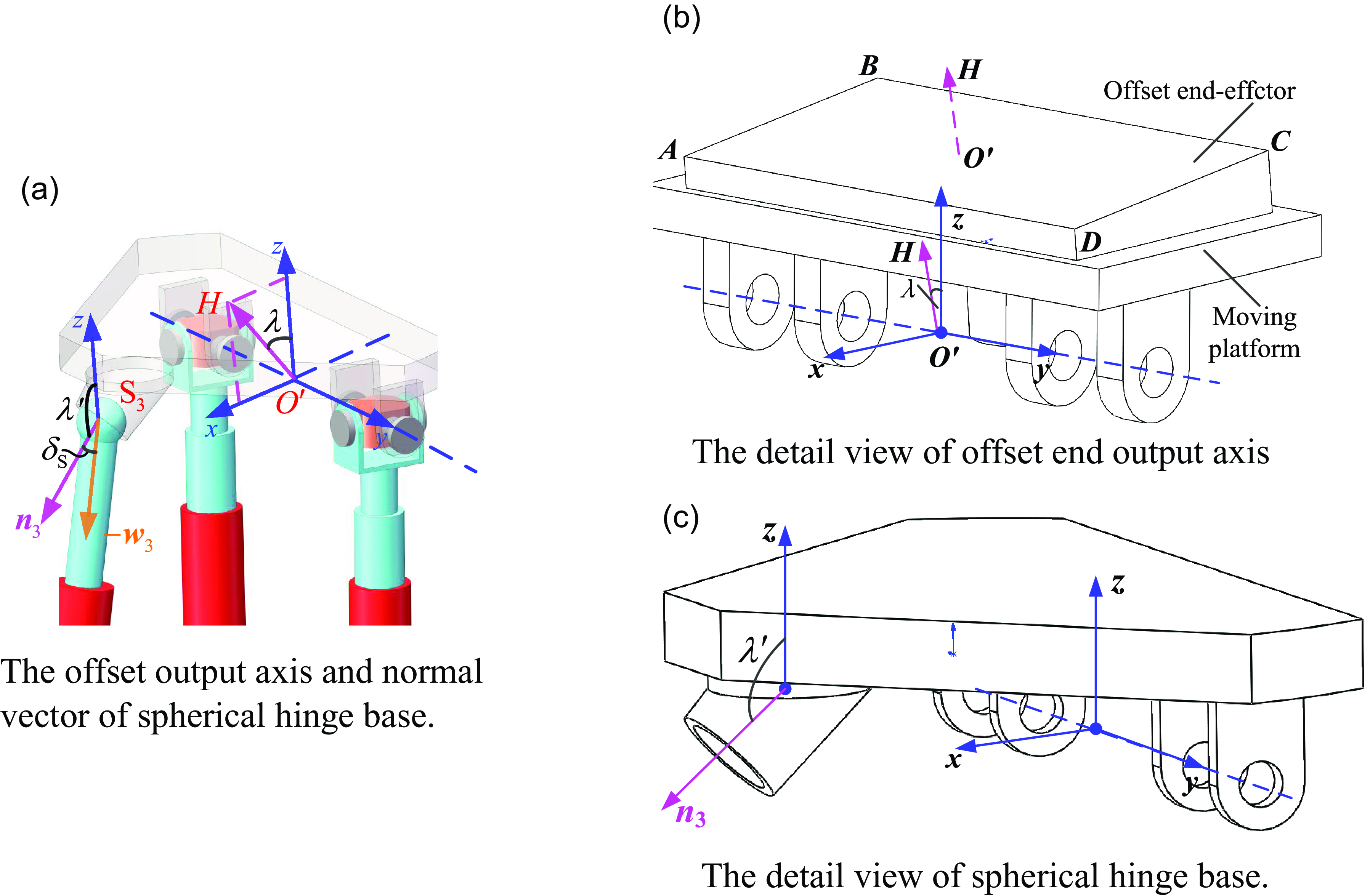
Figure 3 presents the offset type of the end output axis and the spherical hinge base. As shown in Figure 3(a), the O
′
z is essentially the output axis with zero-offset, which is directly perpendicular to the moving platform. Due to the semi-symmetric workspace of 2RPU-RPS PM, O
′
z only has good tilt capability within partial azimuth range. In this paper, the discussed mechanism is used as loading device of a novel hydraulic support test bed, and the tilt direction of tested supports is unknown, thus requiring the end effector of loading device to have good tilt capability in whole azimuth range. Therefore, an appropriate offset angel λ, between O
′
H and O
′
z, can make the output axis O
′
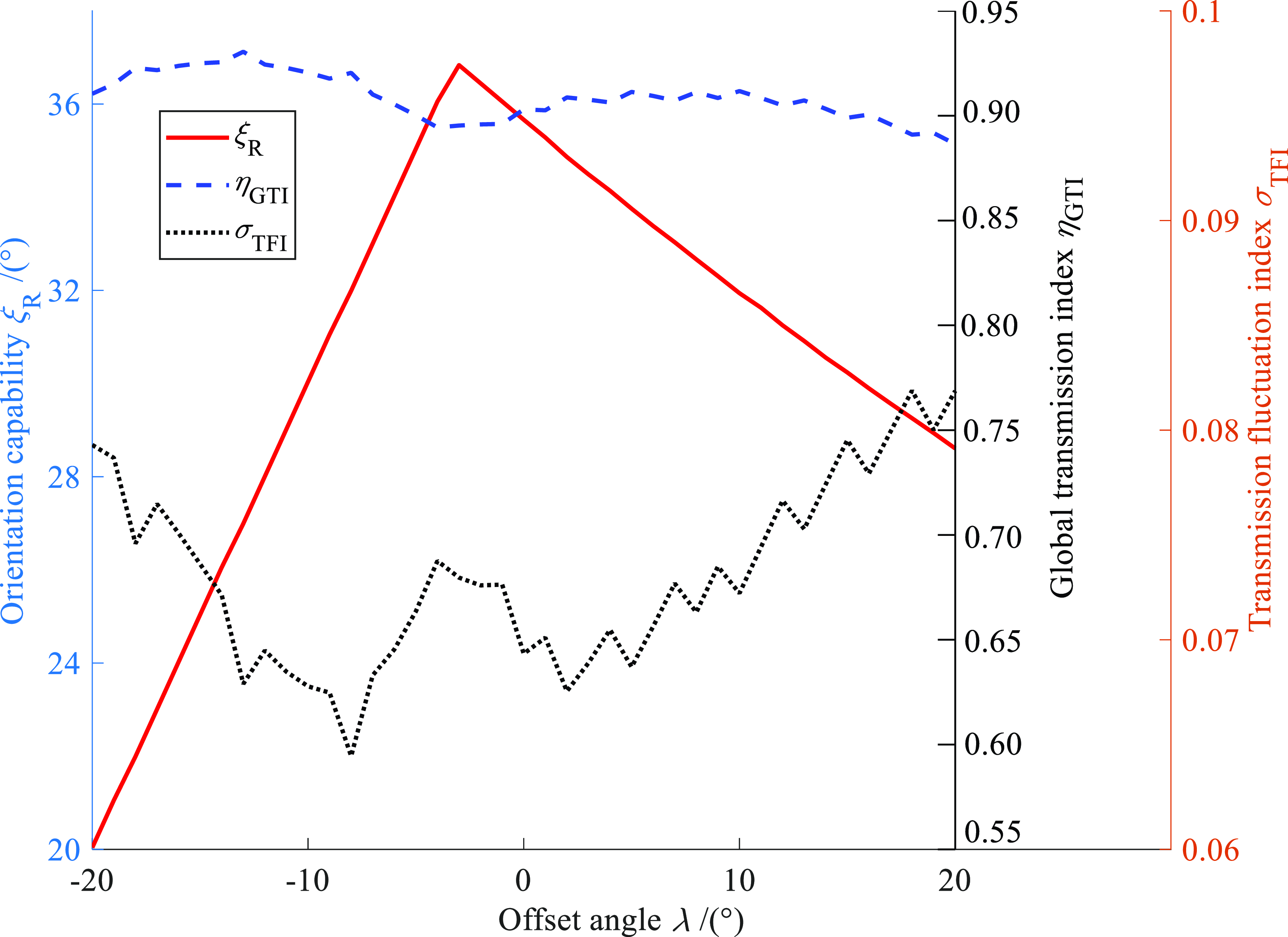
H have good tilt capability in any direction. Moreover, the influence curves of objective functions in Eq. (25) changing with offset angle
 $\lambda$
are also shown in Figure 4. Based on above analysis, the offset angle
 $\lambda$
should be considered as a decision variable.
The schematic diagram of end output axis and spherical hinge base. (a) The offset output axis and normal vector of spherical hinge base. (b) The detail view of offset end output axis. (c) The detail view of spherical hinge base.

The curves of each objective function changing with
 $\lambda$
.

The swing range of spherical joint S3 can affect the tilt capability and orientation workspace of 2RPU-RPS mechanism. Similarly, to enhance swing range of spherical joint, the normal vector of the spherical hinge base
n
3
is also designed as offset, and
 $\lambda \mathit{^{\prime}}$
is the offset angle. From Figure 3(a) and (c), the normal vector of spherical base
n
3 in the {m} is
 $\boldsymbol{n}_{3}=(\sin \lambda \mathit{^{\prime}},0,\cos \lambda \mathit{^{\prime}})^{\mathrm{T}}$
, and then the swing angle of S3 joint is
 $\delta _{\mathrm{S}}=\arccos (-\boldsymbol{n}_{3}^{\mathrm{T}}\boldsymbol{M}^{\mathrm{T}}\boldsymbol{w}_{3})$
. On this basis, the offset angle
 $\lambda \mathit{^{\prime}}$
also should be taken as a decision variable.
According to the above analysis, the decision variables of this multi-objective optimization for dimensional parameters of 2RPU-RPS mechanism are
 \begin{align} \boldsymbol{x}=\left(x_{1},x_{2},\cdots, x_{5}\right)^{\mathrm{T}}=\left(l_{2},l_{3},l_{4},\lambda, \lambda \mathit{^{\prime}}\right)^{\mathrm{T}} .\end{align}
4.3. Constraints
Constraint 1: In engineering application, RTOW is usually used as the working area of PM to facilitate motion planning and control. From Eq. (22), the longer the radius of RTOW, the better the capability of mechanism. Additionally, designers also expect mechanisms to have a good transmissibility and be away from singular area. Combined the above analysis, the constraints about kinematic performance indices are introduced:
 \begin{align} \left\{\begin{array}{l} g_{1}\left(\boldsymbol{x}\right)=15^{\circ }-\xi _{\mathrm{R}}\leq 0\\[3pt] g_{2}\left(\boldsymbol{x}\right)=0\mathit{.}8-\eta _{\mathrm{GTI}}\leq 0.\\[3pt] g_{3}\left(\boldsymbol{x}\right)=\sigma _{\mathrm{TFI}}-0\mathit{.}1\leq 0 \end{array}\right. \end{align}
Constraint 2: Since 2RPU-RPS mechanism is driven by prismatic, the active displacement of each branch chain is limited, that is,
 \begin{align} \left\{\begin{array}{l} g_{3\mathit{+}i}\left(\boldsymbol{x}\right)=\frac{1}{l_{\max }}\max _{\left(\zeta, \xi \right)\in {\Omega _{R}}}\left\{l_{i}\right\}-1\leq 0\\[5pt] g_{6\mathit{+}i}\left(\boldsymbol{x}\right)=1-\frac{1}{l_{\min }}\min _{\left(\zeta, \xi \right)\in {\Omega _{R}}}\left\{l_{i}\right\}\leq 0 \end{array}\right.\left(i=1,2,3\right), \end{align}
where
 $l_{\max }$
and
 $l_{\min }$
are the upper and lower bounds of three active limbs, respectively.
Constraint 3: The swing range of spherical joint S3 is also limited, that is,
 \begin{align} g_{10}\left(\boldsymbol{x}\right)=\max _{\left(\zeta, \xi \right)\in {\Omega _{\mathrm{R}}}}\left\{\left| \delta _{\mathrm{s}}\right| \right\}-\delta _{\mathrm{S},\max }\leq 0 .\end{align}
Constraint 4: This mechanism has the parasitic translation along Y axis, which will increase the complexity of trajectory planning and reduce the working accuracy of the mechanism, thus introducing the constraints as follows:
 \begin{align} g_{11}\left(\boldsymbol{x}\right)=\mathit{|}Y_{P}\mathit{|}\mathit{/}l_{1}-0\mathit{.}2\leq 0 .\end{align}
Constraint 5: The dimension ratio of fixed base and moving platform should be appropriate to satisfy the rod length coordination constraint condition. Thereby, this paper further constructs the rod length constraints, which are
 \begin{align} g_{12}\left(\boldsymbol{x}\right)=\frac{l_{3}}{l_{1}}-0\mathit{.}8\leq 0, \end{align}
 \begin{align} g_{13}\left(\boldsymbol{x}\right)=\frac{l_{4}}{l_{2}}-0\mathit{.}8\leq 0 .\end{align}
The universal joints U1 and U2 are designed as a series connection with the axes of two rotation joints intersecting vertically, which can enhance their swing angles, thus not considering the limitation of swing angles.
Based on the analysis in Sections 4.1∼4.3, it can be concluded that the multi-objective optimization model of 2RPU-RPS mechanism contains 3 objective functions, 5 decision variables, and 13 constrained conditions, which can be defined as an ECMOP model. When solving such problems, the computational cost is very high and many local optimal solutions will be generated during the optimization process. The MOEA is an efficient tool for solving ECMOPs.
4.4. Non-dominated sorting differential evolution algorithm II
The NSGA-II, proposed by Deb [Reference Deb, Pratap, Agarwal and Meyarivan17], is currently one of the most popular MOEA. Compared with NSGA, NSGA-II has the significant advantages of retaining elite individuals, lower complexity, and larger individual distribution. Thereby, this paper applies NSGA-II to solve dimensional optimization model of 2RPU-RPS mechanism. The construction and calculation process of NSGA-II are elaborated in Ref. [Reference Deb, Pratap, Agarwal and Meyarivan17], thus here being omitted.
Additionally, a good evolution operator can accelerate convergence of MOEAs and improve diversity of the new generated individuals. Compared with GA, the differential evolution (DE) algorithm has the significant advantages of strong global search capability and high convergence speed [Reference Opara and Arabas18]. Therefore, the DE algorithm is used as evolution operator in NSGA-II to form a hybrid MOEA named as NSDE-II. The following focus on using NSDE-II to solve the multi-objective optimization model of 2RPU-RPS PM.
4.5. Constraints processing
When using NSDE-II to solve the ECMOP of dimensional parameters for 2RPU-RPS mechanism, 13 inequality constraints included in Eqs. (27)∼(32) should be handled as well. This paper adopts adaptive penalty function method to transform this ECMOP of the discussed mechanism into a multi-objective unconstrained optimization model, and the specific process is as below.
Suppose the candidate solutions to be x and take its constraint violation function is
 \begin{align} f_{\mathrm{vio}}\left(\boldsymbol{x}\right)=\sum _{k=1}^{13}\left\{\left[\boldsymbol{x}\right]_{k}^{+}\cdot \left[1+2\log _{2}\left(1+10^{3}\left[\boldsymbol{x}\right]_{k}^{+}\right)\right]\right\}, \end{align}
where
 $[\boldsymbol{x}]_{k}^{+}$
represents an nonnegative integer, that is,
 $[\boldsymbol{x}]_{k}^{+}=\max \{0,g_{k}(\boldsymbol{x})\}$
.
Subsequently, using Eqs. (23) and (33), we can construct the unconstrained multi-objective function by adaptive penalty function method, which are
 \begin{align} {f^{\prime}_{j}}\left(\boldsymbol{x}\right)=f_{j}\left(\boldsymbol{x}\right)+\chi _{j}^{\left(t\right)}t^{1\mathit{.}5}f_{\mathrm{vio}}\left(\boldsymbol{x}\right), \end{align}
where
 $f_{j}(\boldsymbol{x})(j=1,2,3)$
is objective function, t is the evolutionary generation, that is, t = 1, 2, 3,…, T, T is the maximum evolution generation, and
 $\chi _{j}^{(t)}$
is the t-th generation penalty cardinality.
The decision space of dimensional multi-objective optimization of 2RPU-RPS PM.

5. Implementation of dimensional multi-objective optimization
5.1. Parameter settings
Based on the structural characteristic of 2RPU-RPS mechanism, the lower and upper boundaries of each decision variable are included in Table I. Dimensional parameter l
1 and the workspace section height Z
P
are supposed to be 200 and 450 mm, respectively. The end output axis O′H is located on the moving platform, and its offset angle
 $\lambda$
should not be too large. Conversely, the base of spherical joint S3 is located below the moving platform, which can be installed with a larger offset angle λ′
. The upper boundary of S3 joint δ
S, max is supposed to be 45°.
In this paper, the DE/rand/1/bin version is selected to create new individuals. Hence, the control parameters of NSDE-II mainly includes: population size N
P = 100, non-dominated solutions size N
ns = 40, maximum generation number T
max = 100, scaling factor F = 0.5, and crossover probability C
R = 0.85. Additionally, the search steps for length and angle variables are taken as 2 mm and 1°. The value of
 $\chi _{j}^{(t)}$
in Eq. (34) is taken as 1, since the order of magnitude of
 $f_{j}(\boldsymbol{x})$
is small.
5.2. Multi-objective optimization results analysis
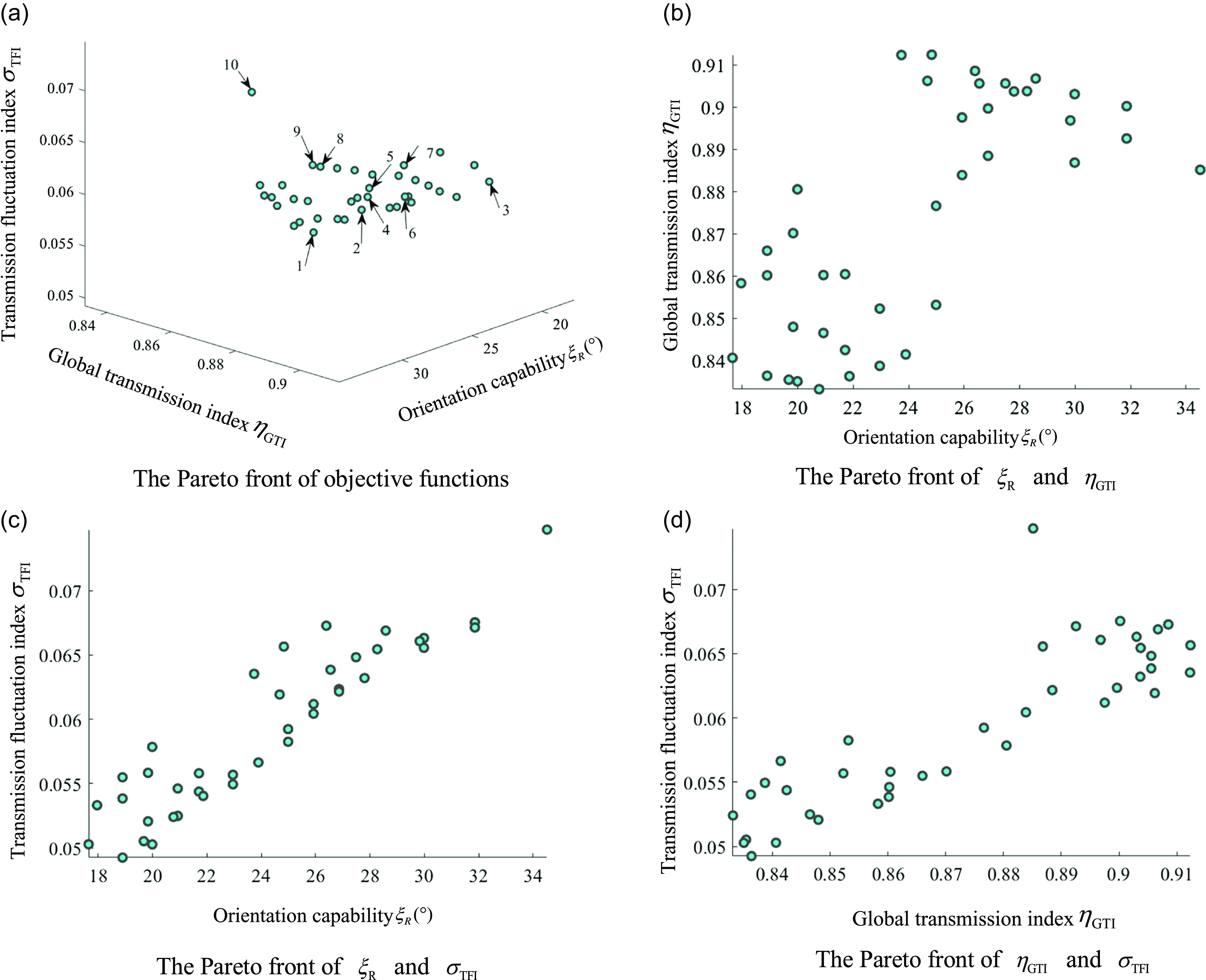
Using NSDE-II to perform multi-objective optimization of 2RPU-RPS mechanism, we obtains the Pareto frontier (PF) presented in Figure 5 when this MOEA runs terminally. Form Figure 5(a), this PF including 40 Pareto optimal solutions has a wide distribution, which can provide multiple alternative solutions for specific engineering design problems. However, due to the competition and coupling between objective functions, this PF of dimensional multi-objective optimization for 2RPU-RPS mechanism is not a smooth surface. Therefore, Figure 6(b)∼(c) further present the two-dimensional PF to qualitatively analyze the relationship between
 $\xi _{\mathrm{R}}, \eta _{\mathrm{GTI}}$
and
 $\sigma _{\mathrm{TFI}}$
.
The Pareto front of dimensional multi-objective optimization for 2RPU-RPS PM. (a) The Pareto front of objective functions. (b) The Pareto front of
 $\xi _{\mathrm{R}}$
and
 $\eta _{\mathrm{GTI}}$
. (c) The Pareto front of
 $\xi _{\mathrm{R}}$
and
 $\sigma _{\mathrm{TFI}}$
. (d) The Pareto front of
 $\eta _{\mathrm{GTI}}$
and
 $\sigma _{\mathrm{TFI}}$
.

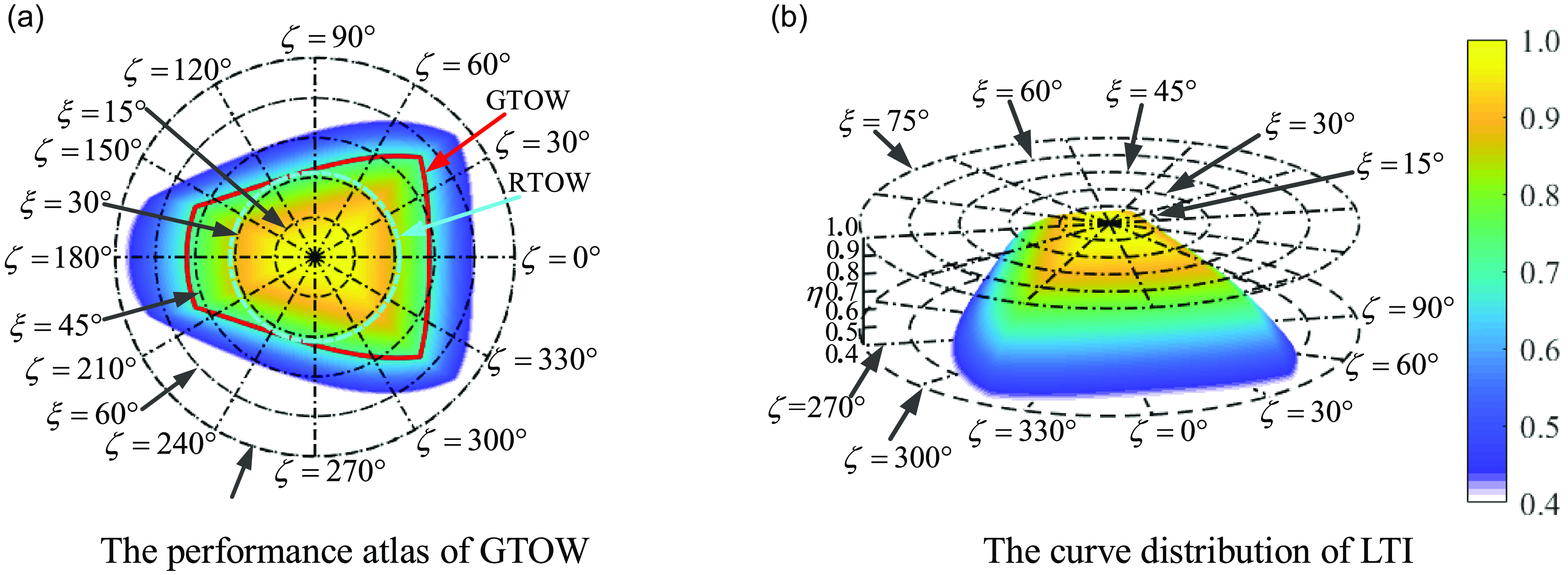
The kinematic performance atlas for the optimized mechanism. (a) The performance atlas of GTOW. (b) The curve distribution of LTI.

From Figure 6(b), the
 $\xi _{\mathrm{R}}$
of the Pareto solutions located in the lower left corner is smaller than those of solutions in the upper right corner, and there is no optimal solution that can make
 $\xi _{\mathrm{R}}$
and
 $\eta _{\mathrm{GTI}}$
achieve optimal situation simultaneously in the upper right corner Pareto solutions. Figure 6(c) shows that the transmission fluctuation performance gradually weakens with the orientation capability increasing, which demonstrates that
 $\xi _{\mathrm{R}}$
and
 $\sigma _{\mathrm{TFI}}$
are two conflicting indices. Similarly, there is also a competitive relationship between
 $\eta _{\mathrm{GTI}}$
and
 $\sigma _{\mathrm{TFI}}$
according to Figure 6(d). Based on the aforementioned analysis, since the three kinematic performance indices of 2RPU-RPS mechanism cannot achieve optimal solutions simultaneously, engineering technicians need to seek a balance point from the 40 Pareto optimal solutions based on specific application demands.
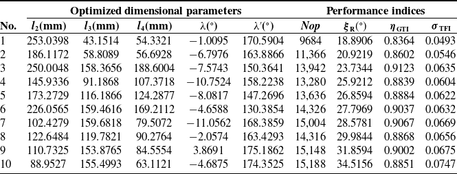
To facilitate technicians to prioritize dimensional parameters, there are 10 typical Pareto optimal solutions being selected from Figure 5(a) and listed in Table II. The performance index Nop, obtained by using discrete analytical method, is the cardinality of all orientation points within the GTOW, which can be quantitatively evaluate the size of orientation workspace on the fixed section. In this table, the
 $\sigma _{\mathrm{TFI}}$
corresponding to optimized dimensional parameters of the first group achieves the minimum, but the size of GTOW is the smallest, and both
 $\xi _{\mathrm{R}}$
and
 $\eta _{\mathrm{GTI}}$
are close to the lower boundaries of constraints in Eq. (27). For the optimization result of the third group,
 $\eta _{\mathrm{GTI}}$
achieved the maximum, but orientation capability of end effector is poor, which cannot meet working situation requiring mechanism to have good tilting capability. Similarly,
 $\xi _{\mathrm{R}}$
in the Pareto solutions of the 10th group is the best, but the fluctuation index is close to the upper set in Eq. (27). The above three groups of Pareto solutions are all called extreme solutions, among which there is at least one poor performance index. Thereby, such solutions are not suitable for guiding engineering application.
Typical Pareto optimal solutions obtained by NSDE-II for solving this case.

The Pareto optimal solutions of 7th, 8th, and 9th groups, known as the compromise solution, have good comprehensive performance, which can be applied to guide practical engineering design. Considering that the application fields of the optimized 2RPU-RPS mechanism should be as wide as possible, we select the optimization result of 9th group (rounded) to further analyze the kinematic performance of 2RPU-RPS PM.
By the means of discrete analytical principle, the kinematic performance atlas corresponding to the selected Pareto optimal solution is presented in Figure 6. Moreover, the polar coordinate search method and bisection method are both used to obtain the boundary curves of GTOW and ROTW. Figure 6(a) focuses on showing the workspace performance and motion/force transmissibility, and Figure 6(b) gives the curve distribution of LTI within workspace.
In Figure 6(a), the blank area is the point set of unreachable orientation points caused by inequality constraints Eqs. (27)∼(32), and these poses are also close to singular boundary. The red line is the contour corresponding to the
 $\eta _{\mathrm{LTI}}=[\eta ]=0\mathit{.}7$
, and its MIC is represented by the blue dotted line. The area enclosed by red line is the GTOW, and its MIC is the RTOW. Based on the analysis in Section 3, the input motion/force transmissibility is good in all orientations, and the output transmission singularity is unlikely to happen within GTOW. From Figure 6(a), there is no internal hole in the GTOW for the optimized PM, which indicates that the end effector of 2RPU-RPS mechanism can move continuously. Additionally, the GTOW is symmetric with polar radius
 $\zeta =0^{\circ}$
(
 $\zeta =180^{\circ}$
), but asymmetric with polar radius
 $\zeta =90^{\circ}$
(
 $\zeta =270^{\circ}$
), which is also consistent with the planar symmetric structural characteristic of the discussed mechanism and further demonstrates the reasonability of the optimization result. From Figure 6(b), the curve of LIT is smooth, which indicates that the optimized mechanism has a good and stable motion/force transmissibility.
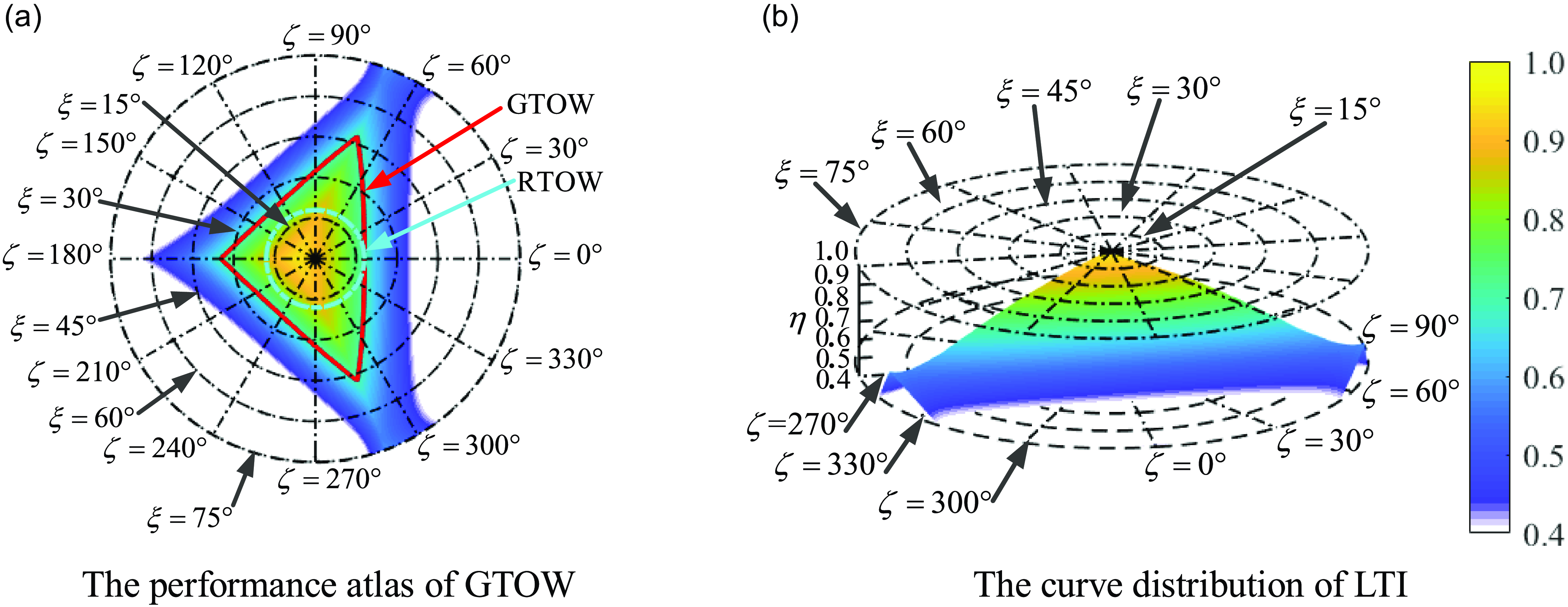
For comparison, the original dimensional parameters and kinematic performance indices are included in Table III, and the corresponding performance atlas is shown in Figure 7. From Figure 6(a) and 6(a), the GTOW and RTOW of the optimized mechanism are significantly larger than those of the original mechanism, and there are orientation points close to the singular boundary when LTI ranges from 0.4 to 1. From Figures 6(b) and 7(b), there are holes on the boundary of the LTI curve for original mechanism. By comparing kinematic performance indices, it is found that the orientation capability
 $\xi _{\mathrm{R}}$
and cardinality of GTOW are increased by 76% and 35%. Additionally, the GTI
 $\eta _{{_{\mathrm{GTI}}}}$
becomes better while the TFI has slightly decreased, which also conforms to the fact that multi-objective optimization can not make all performance indices optimal.
Based on aforementioned analysis, the orientation capability, workspace performance, and motion/force transmissibility of the optimized 2RPU-RPS mechanism have been significantly improved, which proves that that the modeling method and solving algorithm of this multi-objective optimization are correctness and effectiveness.
The kinematic performance indices of original design mechanism.

The kinematic performance atlas for the original mechanism. (a) The performance atlas of GTOW. (b) The curve distribution of LTI.

5.3. Computational performance evaluation of NSDE-II
To verify the effectiveness and robustness of NSDE-II, the MOEA/D (multi-objective evolution algorithm based on decomposition) and NSGA-II are applied to solve this ECMOP of 2RPU-RPS mechanism. Due to the fact that the model solved in this paper is an engineering application problem and its true PF is unknown, the performance indices and testing functions with the known true Pareto front are not suitable for evaluating and testing the robustness of the NSDE-II [Reference Wang, Ren and Qiu19]. Moreover, designers are often more interested in the distribution breadth of each Pareto solutions set X pa rather than uniformity. The wider the distribution of X pa, the more alternative solutions can be provided for engineering design and application.
Based on aforementioned analysis, two indices that do not rely on the true PF are used to evaluate the computational performance of the four MOEAs, including the normalization coverage space (NCS) and the minimum adjacent vector angle. The former is used to evaluate the degree of mutual dominance between two Pareto solution sets, and the latter directly reflects the distribution width the obtained X pa.
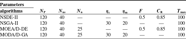
To be fair, the GA and DE evolution algorithms are also integrated into MOEA/D to form MOEA/D-GA and MOEA/D-DE, and the Deb′s feasibility rule [Reference Che, Chen, Jiang, Du and Wen20] is used to handle the inequality constraints Eqs. (27)∼(32). Meantime, the control parameters of the four MOEAs are included in Table IV. Meantime, N n is the neighborhood size of MOEA/D, and η c and η m are the crossover distribution coefficient and mutation distribution coefficient, respectively. In addition, the process of MOEA/D for solving multi-objective optimization has been detailed in Ref. [Reference Zhang and Li21].
Control parameters of the four MOEAs.

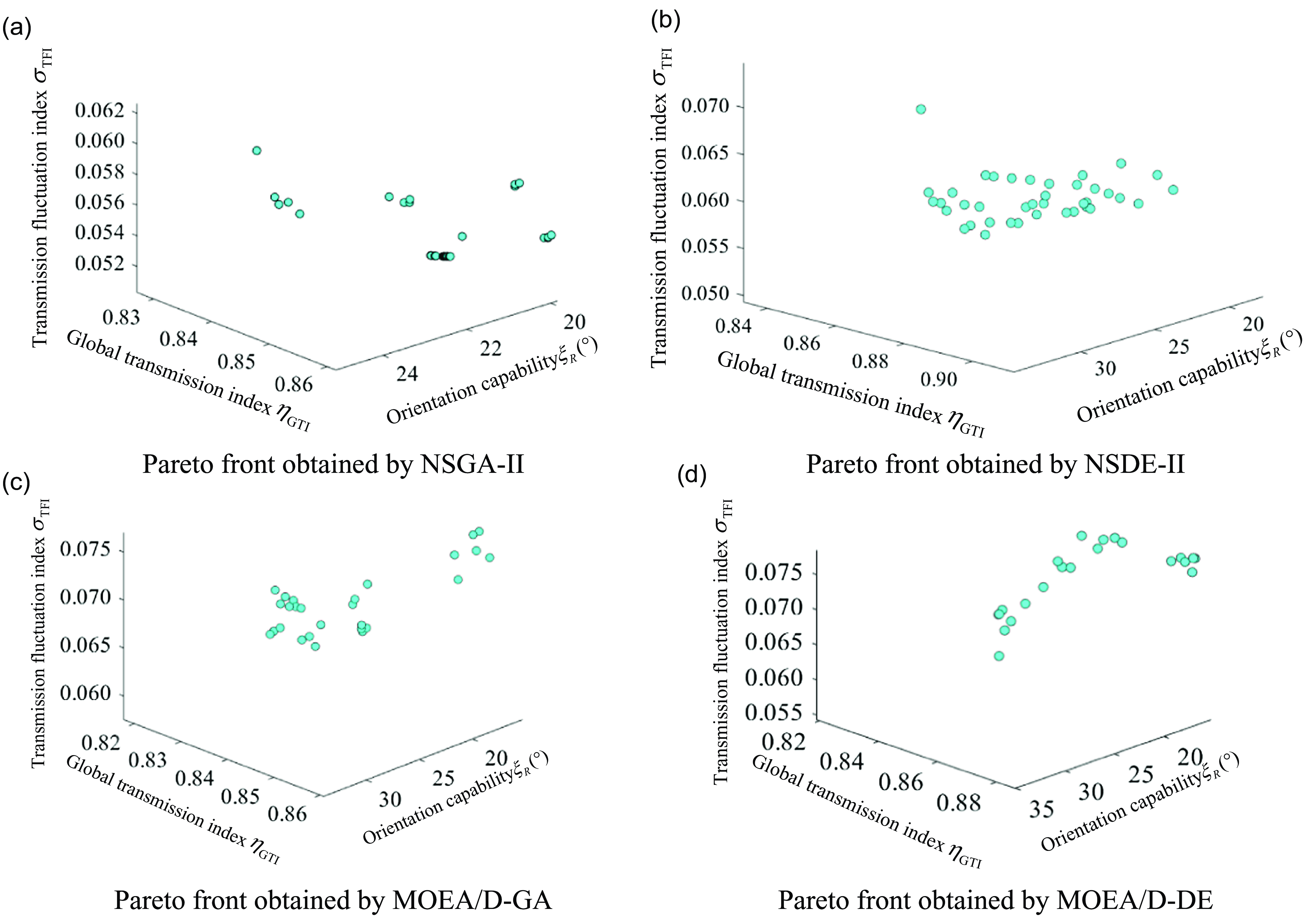
Pareto fronts obtained by four MOEAs. (a) Pareto front obtained by NSGA-II. (b) Pareto front obtained by NSDE-II. (c) Pareto front obtained by MOEA/D-GA. (d) Pareto front obtained by MOEA/D-DE.

Figure 8 presents the Pareto front obtained through each MOEA. The multi-objective optimization modeling of 2RPU-RPS mechanism is an engineering application problem, whose true Pareto front is unknown. Moreover, engineering technicians are more interested in the distribution breadth of each Pareto solutions set X pa to provide more alternative options. Based on the above analysis, two indices that not rely on the true PF are used to evaluate the computational performance of the four MOEAs, including the NCS and the minimum adjacent vector angle.
Due to the nonuniform dimension of three objective functions,
 $\xi _{\mathrm{R}}, \eta _{\mathrm{GTI}}$
and
 $\sigma _{\mathrm{TFI}}$
are needed to be normalized. Suppose P
′ and P” to be Pareto solution sets, and then set the extreme values of their objective functions to
 $(f_{\mathit{j,}\min }^{\prime},f_{\mathit{j,}\max }^{\prime})$
and
 $(f_{\mathit{j,}\min }^{\prime\prime},f_{\mathit{j,}\max }^{\prime\prime})$
. After normalizing each objective function, we can obtain
 \begin{align} f_{j}^{\prime}=\frac{f_{\mathit{j,}\max }^{\prime}-f_{\mathit{j,}\min }^{\prime}}{f_{\mathit{j,}\max }-f_{\mathit{j,}\min }}, \end{align}
 \begin{align} f_{j}^{\prime\prime}=\frac{f_{\mathit{j,}\max }^{\prime\prime}-f_{\mathit{j,}\min }^{\prime\prime}}{f_{\mathit{j,}\max }-f_{\mathit{j,}\min }}, \end{align}
where
 $f_{j,\max }=\max \![f_{\mathit{j,}\max }^{\prime},f_{\mathit{j,}\max }^{\prime\prime}], f_{j,\min }=\min [f_{\mathit{j,}\min }^{\prime},f_{\mathit{j,}\min }^{\prime\prime}]$
, j = 1, 2, ……, m, and m represents the number of objective function, that is, m = 3.
Subsequently, the NCS of P ′ and P” can be formulated as:
 \begin{align} \mathit{NCS}_{P^{\prime}}=\prod _{j=1}^{m}f_{j}^{\prime}, \end{align}
 \begin{align} \mathit{NCS}_{P^{\prime\prime}}=\prod _{j=1}^{m}f_{j}^{\prime\prime} .\end{align}
From Eqs. (35)∼(38),
 $\mathit{NCS}_{P^{\prime}}$
and
 $\mathit{NCS}_{P^{\prime\prime}}$
, ranging from 0 to 1, together represent mutual coverage of two Pareto solution sets. For both, the one taking larger value has a better Pareto solutions set. On this basis, the NCS of four Pareto solution sets are compared one by one, and the corresponding results are listed in Table V. As can be seen from this table, the NCS of Pareto solution set X
pa(NSDE-II) obtained through NSDE-II is maximum, while that of X
pa(NSGA-II) is minimum, which indicates that the Pareto front obtained through NSDE-II the closest to the true PF of this engineering optimization problem.
The minimum adjacent vector angle
 $\theta _{V}$
is proposed in this paper to evaluate the distribution breadth of Pareto solution set. Similarly, the three objective functions also need to be normalized, then the normalization objective function of any individual
 $\boldsymbol{x}_{s}$
in the decision space is
 \begin{align} f_{j}^{s}\left(\boldsymbol{x}_{s}\right)=\frac{f_{j}\left(\boldsymbol{x}_{s}\right)-f_{\mathit{j,}\min }}{f_{\mathit{j,}\max }-f_{\mathit{j,}\min }} \end{align}
where
 $f_{j,\min }=\min _{{\boldsymbol{x}_{s}}\in \Omega }f_{j}(\boldsymbol{x}_{s}), f_{j,\max }=\max _{{\boldsymbol{x}_{s}}\in \Omega }f_{j}(\boldsymbol{x}_{s})$
and
 $\Omega$
represents the decision space.
Based on Eq. (39), the vector angle of ant two individuals
 $\boldsymbol{x}_{{s_{1}}}$
and
 $\boldsymbol{x}_{{s_{2}}}$
in the objective space can be expressed as:
 \begin{align} \theta _{\mathrm{Va}}=\arccos \left(\frac{\left(\boldsymbol{f}^{s}\left(\boldsymbol{x}_{{s_{1}}}\right)\right)^{\mathrm{T}}\boldsymbol{f}^{s}\left(\boldsymbol{x}_{{s_{2}}}\right)}{\left\| \boldsymbol{f}^{s}\left(\boldsymbol{x}_{{s_{1}}}\right)\right\| _{2}\cdot \left\| \boldsymbol{f}^{s}\left(\boldsymbol{x}_{{s_{2}}}\right)\right\| _{2}}\right) \end{align}
where
 $\boldsymbol{f}^{s}(\boldsymbol{x}_{s})\mathit{=}(f_{1}^{s}(\boldsymbol{x}_{s}),f_{2}^{s}(\boldsymbol{x}_{s}),\cdots, f_{m^{\prime}}^{s}(\boldsymbol{x}_{s}))^{\mathrm{T}}$
.
The comparison results of the normalization coverage space.

From Eq. (40), the evaluation method based on
 $\theta _{\mathrm{Va}}$
for distribution breadth of Pareto solution set can be described as below. First, set an extreme Pareto solution to the first individual, then use Eq. (40) to calculate all vector angles between remaining individuals and the first individual, and finally determine the individual corresponding the minimum vector angle
 $\theta ^{\prime}_{\mathrm{Va}}$
as the second individual. Analogously, we can obtain (N
ns-1) minimum vector angles until all the individuals are sorted and the mean of all minimum adjacent vector angles
 $\overline{\theta ^{\prime}_{\mathrm{Va}}}$
can be directly solved. According to the above definition, the larger
 $\overline{\theta ^{\prime}_{\mathrm{Va}}}$
, the wider the distribution of Pareto solution set, that is, the better the diversity of the obtained
 $X_{\mathrm{Pa}}$
.
To quantitively compare the computational performance of the four MOEAs, the size of Pareto optimal solutions, CPU time consumption, and
 $\overline{\theta ^{\prime}_{\mathrm{Va}}}$
of each algorithm are listed in Table VI. As can be seen from this table, two MOEAs based on dominated strategy are superior to the two algorithms based on decomposition in terms of N
ns and CPU time consumption, that is, the former two MOEAs can provide more alternative solutions for engineering design with less computational cost. Combined with the results in Table V, NSGA-II is more time-saving than NSDE-II, but NSDE-II significantly outperforms NSGA-II in NCS and the distribution breadth. In summary, the NSDE-II designed in this paper has the optimal comprehensive performance.
Performance indices of four MOEAs.

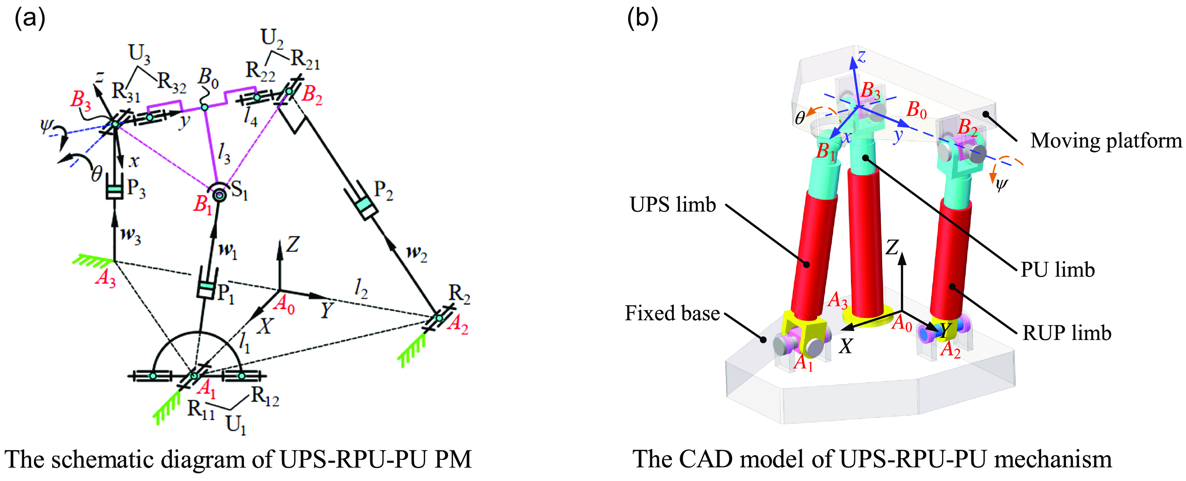
Moreover, the NSDE-II is used to solve the ECMOP of the asymmetric UPS-RPU-PU mechanism in Ref. [Reference Peng, Cheng, Che, Zheng and Cao11] to further support the feasibility of this optimization procedure. The schematic diagram of UPS-RPU-PU mechanism is illustrated in Figure 9. From this figure, the multi-objective functions remain as Eq. (41), but the decision variables are changed as follows:
 \begin{align} \boldsymbol{x}^{\prime}=\left(l_{2},l_{3},l_{4},\phi, \lambda, \phi _{1},\lambda _{1}\right)^{\mathrm{T}}, \end{align}
where
 $\phi$
and
 $\lambda$
are the structure parameters of offset output axis, and
 $\phi _{1}$
and
 $\lambda _{1}$
are the offset angles of normal vector of the spherical hinge base relative to the positive direction of z-axis.
UPS-RPU-PU parallel mechanism. (a) The schematic diagram of UPS-RPU-PU PM. (b) The CAD model of UPS-RPU-PU mechanism.

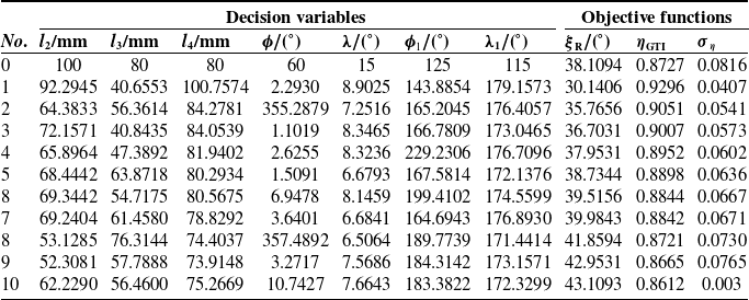
Eq. (42) presents the constrained conditions of multi-objective optimization model of UPS-RPU-PU mechanism. The corresponding parameters in inequality equation are elaborated in Ref. [Reference Peng, Cheng, Che, Zheng and Cao11]. The control parameters of NSDE-II are the same as those in Table IV. Clearly, the ten-group typical dimensional multi-objective optimization results of UPS-RPU-PU mechanism are included in Table VII, and 10th group represents performance indices under original design dimensional parameters:
 \begin{align} \mathrm{s}.\mathrm{t}.\,\,\left\{\begin{array}{l} \xi _{\mathrm{R}}\geq 30^{\circ } \\[3pt] \eta _{\mathrm{GTI}}\geq 0\mathit{.}7\\[3pt] \sigma _{\eta }\leq 0\mathit{.}1\\[3pt] q_{\min }\leq q_{i}\leq q_{\max }\left(i=1,2\right)\\[4pt] \left| \theta _{i}\right| \leq \delta _{\mathrm{U},\max }\left(i=1,2\mathit{,}3\right)\\[4pt] \left| \psi _{i}\right| \leq \delta _{\mathrm{U},\max }\left(i=1,2\mathit{,}3\right)\\[4pt] \left| \delta _{\mathrm{S},1}\right| \leq \delta _{\mathrm{S},\max } \end{array}\right. \end{align}
As can be seen from Table VII, the performance index
 $\xi _{\mathrm{R}}$
in 10th group is clear to result of the single-objective optimization in Ref. [Reference Peng, Cheng, Che, Zheng and Cao11], which indicates that the results of multi-objective optimization are correct and reliable. Subsequently, the aforementioned remaining three MOEAs are further used to solve the ECMOP of UPS-RPU-PU mechanism, then the NCS and
 $\overline{\theta ^{\prime}_{\mathrm{Va}}}$
of the four MOEAs are included in Table VIII and Table IX, respectively.
Typical Pareto optimal solutions obtained by NSDE-II for UPS-RPU-PU mechanism.

In Table VIII, the NCS of Pareto solution set X
pa(NSDE-II) obtained through NSDE-II is also maximum, which shows that the quality of Pareto solutions obtained by NSDE-II is the best, and the dominate order of Pareto solution set obtained by each algorithm can be written as
 $X_{\mathrm{Pa}(\text{NSDE-II})}\succ X_{\mathrm{Pa}(\text{NSGA-II})}\succ X_{\mathrm{Pa}(\text{MOEA}/\mathrm{D}-\mathrm{DE})}\succ X_{\mathrm{Pa}(\text{MOEA}/\mathrm{D}-\mathrm{GA})}$
. In Table IX, the performance index
 $\overline{\theta ^{\prime}_{\mathrm{Va}}}$
of MOEA/D-GA and MOEA/D-DE are better than those of NSGA-II and NSDE-II, but the size of non-dominated solution set N
ns of the first two MOEAs are significantly smaller than the latter two MOEAs, which proves that
 $X_{\mathrm{Pa}(\text{NSDE-II})}$
and
 $X_{\mathrm{Pa}(\text{NSGA-II})}$
are clear to true PF of this multi-objective optimization problem. For CPU time consumption, the computational cost of NSDE-II is lower than two MOEAs based on decomposition.
The normalization convergence space of Pareto solutions for UPS-RPU-PU PM.

Performance indices of four MOEAs for solving optimization model of UPS-RPU-PU PM.

Based on above analysis, NSDE-II is superior to other three algorithms in convergence, efficiency, and diversity. Consequently, combining the above two multi-objective optimization cases, we can concluded that NSDE-II has good robustness in solving multi-objective engineering optimization problems whose true PF is unknown.
6. Application case of optimized 2RPU-RPS PM
In fully mechanized mining, hydraulic support plays a crucial role in supporting coal mine roof and ensuring the safety of underground technicians. Therefore, before the novel hydraulic support is put into use, the loading test needs to be carried on its sample to verify whether the strength and durability are qualified. The existing loading test bed can only simulate the vertical compression conditions of canopy and base of hydraulic support and cannot conduct loading test for shield beam, tail beam, and supports with inclined coal seam.
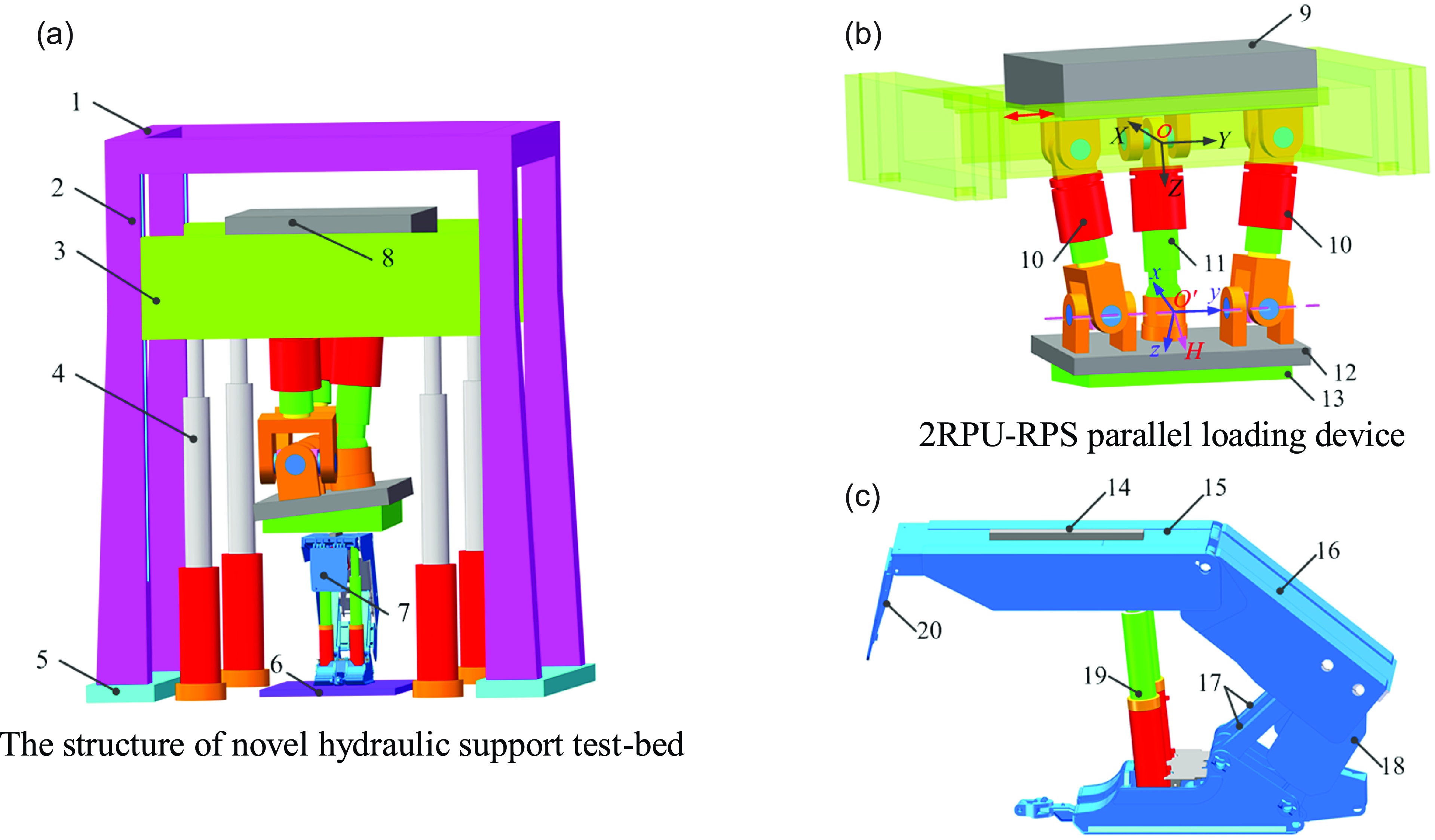
Due to the large orientation capability and good force transmissibility, the optimized 2RPU-RPS PM is used as the loading device for the novel hydraulic support test bed. Figure 10 presents the virtual prototype of the novel hybrid loading test bed of hydraulic support. From Figure 10(a), the fixed frame composed of upper beam, columns, and bottom beam can provide a closed area for the tested support, and the 3-DOF parallel loading device (shown in Figure 10(b)), moving along the Y axis, is installed on the floating beam. The ZY9200/25/50/D type support (shown in Figure 10(c)) is taken as test objective to verify the feasibility of the novel test bed based on 2RPU-RPS mechanism.
During the loading test, contract the sprag, place the tested support on the workbench and adjust the parallel loading device to an appropriate position according to the test height of hydraulic supports (i.e., two-thirds of maximum height). Subsequently, the deviating loading spindle on the moving platform is driven by the three active limbs to contact the loading pad, and then the corresponding compression condition is simulated. Figure 10 is the legend of longitudinal middle loading, and other legends are elaborated in Ref. [Reference Wang22]. The loading legends of shield beam and supports with inclined coal seam are presented in Figure 11, and their corresponding inclination angles are 20° and 25°. Combined with the results in Section 5.2, the orientation capability of the optimized 2RPU-RPS PM can satisfy the condition of rational loading for hydraulic supports.
The virtual prototype of novel hydraulic support test bed. (a) The structure of novel hydraulic support test bed. (b) 2RPU-RPS parallel loading device. (c) ZY9200/25/50/D type hydraulic support. 1. Upper beam, 2. Closed frame, 3. Floating beam, 4. Lifting hydraulic cylinder, 5. Bottom beam, 6. Workbench, 7. ZY9200/24/50D type hydraulic support, 8. 2RPU-RPS parallel loading device, 9. The base, 10. RPU chain, 11. RPS chain, 12. Moving platform, 13. Deviating loading spindle, 14. Loading pad, 15. Canopy, 16. Shield beam, 17. Linkage, 18. Tail beam, 19. Column, 20. Sprag.

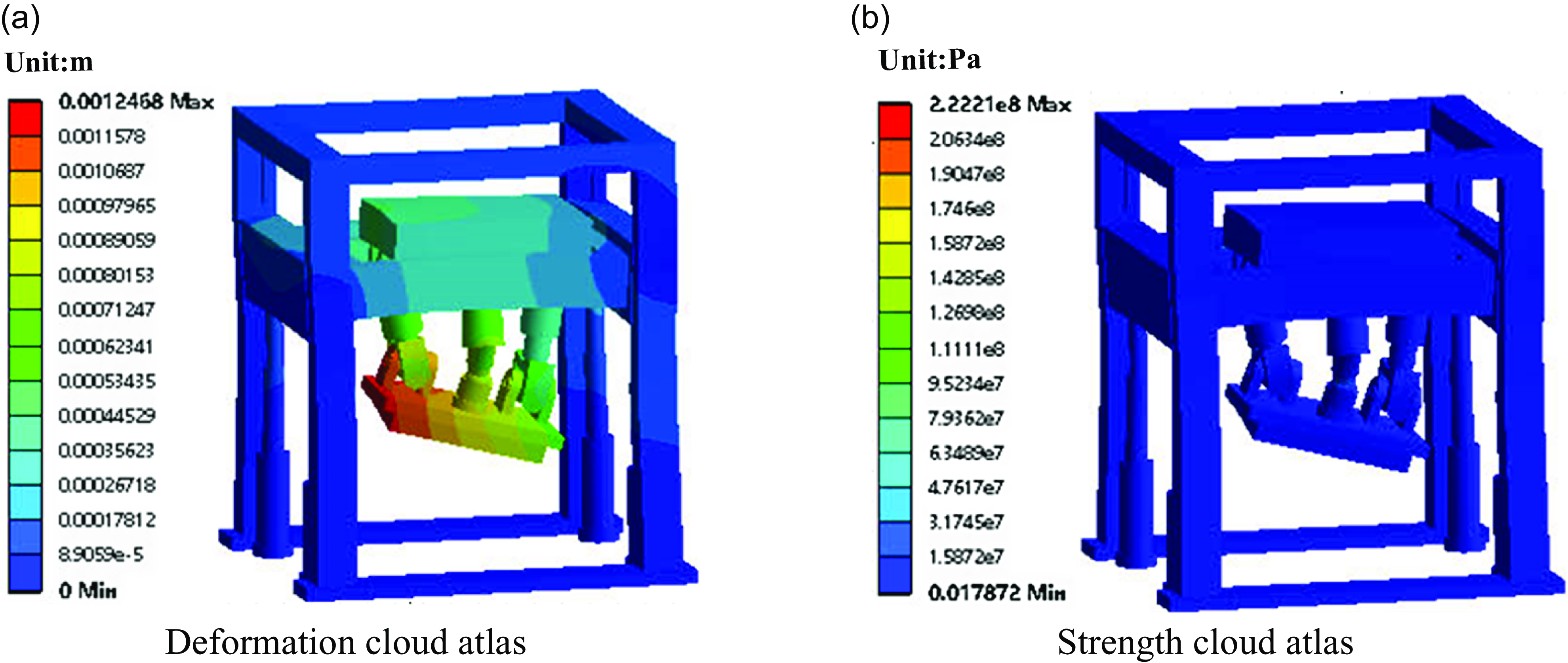
Taking Q460C as the main material and determining the safe coefficient is 2, we can perform static analysis for the novel test bed designed in this paper. The maximum loading capability of existing external test bed is 22 MN, thus imposing this load on the novel hybrid test bed. Figures 12∼14 presents the deformation and strength of the three typical working conditions of this novel hydraulic support test bed.
The two rational loading test of hydraulic support. (a) The loading test for shield beam. (b) The loading test for inclined hydraulic support.

Static analysis results of longitude middle loading for canopy. (a) Deformation cloud atlas. (b) Strength cloud atlas.

Static analysis results of loading for shield beam. (a) Deformation cloud atlas. (b) Strength cloud atlas.

Static analysis results of loading for inclined hydraulic support. (a) Deformation cloud atlas. (b) Strength cloud atlas.

From Figures 12(a)∼14(a), the maximum deformation for three loading conditions are 0.9652, 1.2468, and 1.747 mm, respectively. Compared to the overall size of the designed novel test bed (10,550 mm × 5350 mm × 9500 mm), the above deformation can be considered as mirror deformation and does not affect the operation of this novel test bed under 22 MN external loading. Similarly, the strength for each loading condition are shown in Figures 12(b)∼14(b), and the corresponding maximum stresses are all within the allowable range, that is, 230 MPa.
Due to the standardization and serialization of the structure and type for hydraulic supports, it can be concluded that the bearing capability, orientation workspace, and motion/force transmissibility of the novel test bed can meet test demands for the majority of hydraulic supports on the market, which also indicates that the optimized 2RPU-RPS PM has good application prospect in the field of loading test for hydraulic supports.
7. Conclusions
-
1. The 2RPU-RPS PM is taken as research object, and its multi-objective dimensional optimization problem is solved by NSDE-II. Meanwhile, the eECMOP modeling method proposed in this paper is also applicable to other PMs.
-
2. Employing the NSDE-II to solve this ECMOP, we obtain 40 sets of Pareto optimal solutions, which can provide multiple alternative solutions for engineering design. By comparing, the GTOW cardinality and RTOW of compromise solution are increased by 76% and 35%, and the optimized 2RPU-RPS PM has better motion/force transmissibility as well. The multi-objective optimization results show that the proposed model and algorithm are feasible and effective.
-
3. The NCS and the minimum adjacent vector angles are proposed to evaluate computational capability of NSGA-II, NSDE-II, MOEA/D-GA, and MOEA/D-DE, and the experiments demonstrate that NSDE-II has the optimal global computational performance.
-
4. Based on the optimized 2RPU-RPS PM, a novel hydraulic support test bed is designed to solve technical difficulties of existing test bed. The static analysis results proves that this mechanism has a potential application prospect as the loading device of hydraulic supports.
Financial support
This work was sponsored by the Science and Technology Research Project of Chongqing Municipal Education Commission, China (Grant No. KJZD-K202303404), the Doctoral Scientific Research Foundation of Suzhou University (Grant No. 2023BSK016), the Science and Technology Research Project of Chongqing Municipal Education Commission, China (Grant No. KJQN202100845), and the Key Fund for Scientific Research Projects of Chongqing Technology and Business of University (Grant No. 2152003).
Author contributions
Siyang Peng and Linxian Che conceived and designed this study. Li Du performed statistical analysis. Zujin Jin conducted data gathering. Siyang Peng wrote this article.
Competing interests
The authors declare no conflicts of interest exist.
Ethical standards
Not applicable.