I. INTRODUCTION
As the lightest structural metal, magnesium alloys have high specific strength and good machinability and are attractive for aerospace, automobile, and electronic applications. Mg alloys can be classified into two broad groups: Al free and Al bearing. Although Mg–Al alloys have been widely used due to their good room temperature mechanical properties and castability, their poor creep resistance and significant reduction in tensile stress at elevated temperatures (>150 °C) limit their industrial application.Reference Pekguleryuz and Celikin1 In contrast, Mg alloys containing rare-earth (RE) elements (Mg–RE alloys) have attracted a lot of interest because of their better mechanical properties at elevated temperatures.Reference Pekguleryuz and Celikin1 Among various Mg–RE alloys, the Mg–Gd system is particularly promising owing to the dramatic precipitation strengthening response and thermally stable main strengthening phase.Reference Gao and Nie2, Reference Gao, He, Zeng, Peng, Ding and Nie3
Grain refinement often leads to a refinement of secondary phases and a reduction in microsegregation and improves the ductility, strength, machinability, and castability of alloys.Reference StJohn, Qian, Easton, Cao and Hildebrand4, Reference Vinotha, Raghukandan, Pillai and Pa5 Mg alloys have a high Hall–Petch coefficient,Reference Kubota, Mabuchi and Higashi6 thus grain refinement increases their strength considerably. It has also been found that refining the grain size can reduce the steady-state creep rate in cast Mg–RE alloys.Reference Bettles, Gibson and Zhu7 There has been a lot of research on the grain refinement of Mg alloys.Reference StJohn, Qian, Easton, Cao and Hildebrand4 Zr is a very powerful grain refiner for Al-free alloys,Reference StJohn, Qian, Easton, Cao and Hildebrand4 and it is often introduced through adding commercial binary Mg–Zr master alloys containing Zr particles ranging from submicrometer to about 50 μm in size.Reference Qian, StJohn and Frost8 Despite the grain refining efficiency of Zr, the use of Mg–Zr master alloys has some disadvantages. First, Mg–Zr master alloys are expensive and increase the cost of production.Reference Qian, Hildebrand and StJohn9 Second, the utilization rate of Zr is low since the undissolved Zr particles spontaneously settle due to the much higher density of Zr (6.52 g/cm3) compared to pure Mg melt (∼1.58 g/cm3).Reference Qian, Zheng, Graham, Frost and StJohn10
Recently, it has also been reported that some Al2RE particles can act as heterogeneous substrates of α-Mg. Jie et al.Reference Jie, An, Tian, Jun, Yuan and Qing11 found that the microstructure of Mg–6Al–0.6Zn alloy was refined by the addition of Sm, and Al2Sm particles were believed to promote heterogeneous nucleation during solidification. Qiu et al.Reference Qiu, Zhang, Taylor and Kelly12 identified Al2Y to be an effective grain refiner in a Mg–10Y alloy and found that the thermal stability of the fine grains in Mg–10Y–1Al alloy was excellent. Li et al.Reference Li, Zhou and Li13 investigated the effect of Gd on the microstructure and rolling capability of AZ31 alloy, and it was found that with Gd addition, the grain size was refined. However, the grain refinement mechanism was not explained. Wang et al.Reference Wang, Du, Liu, Wang and Li14 reported that adding Gd into a Mg–2Al–1Zn alloy led to the formation of (Mg,Al)3Gd and Al2Gd followed by the increase of tensile properties at both room temperature and elevated temperature, but no grain refinement was mentioned. In the present work, the grain refining behavior of adding Al into a Mg–10Gd binary alloy was investigated. The orientation relationships (ORs) between nucleant particles and primary α-Mg were predicted and identified, and the thermal stability of the fine grains in the as-cast Mg–10Gd–1Al alloy was investigated as well. This work provides a reason to investigate the grain refinement of Mg–Gd-based alloysReference He, Zeng, Peng, Gao, Nie and Ding15–Reference Zheng, Dong, Zeng and Ding17 by the addition of Al.
II. EXPERIMENTAL
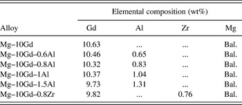
The Mg–10Gd alloy was made from pure Mg ingots and Mg–25% Gd master alloy (Light alloy Co., Ltd., Ganzhou FT, China) (all percentages are weight percentage in this work) in an electric furnace under the protection of mixed cover gas consisting of CO2 and SF6 with the volume ratio of 100:1. Pure Al was added into the melt ranging from 0.6 to 1.3% at 730 °C. After being stirred for 2 min, the melt was held at 730 °C for 30 min to let Gd and Al react completely and was then poured into steel molds with 15 mm in diameter preheated at 200 °C. As a comparison for the grain refining efficiency of adding Al, a grain refining treatment was also performed by addition of 0.8% Zr using a commercially available Mg–30% Zr master alloy (Suzhou Qilin Alloy Mould Co., Ltd., Suzhou, China) into the Mg–10Gd alloy. The nominal total addition of Zr to achieve this was 2%. The Mg–10Gd–0.8Zr alloy was cast under the same conditions. The actual compositions of all alloys were determined by Optima 7300DV inductively coupled plasma atomic emission spectroscopy (PerkinElmer Inc., Waltham, MA) and are listed in Table I. To estimate the thermal stability of fine grains, the Mg–10Gd–1Al alloy was solution treated at 550 °C for 48 h followed by a water quench and the as-solution-treated grain size was compared with the as-cast grain size.
Chemical compositions of the alloys studied in this work.

(Balance abbreviated to Bal.)
Samples for optical microscopy (OM) (Carl Zeiss Company, Oberkochen, Germany) were polished and then etched in an acetic–picric solution (10 mL acetic acid, 6 g picric acid, and 8 mL H2O in 70 mL ethanol). The grain size was measured by a linear intercept method under the OM. The phase identities were determined by a D/MAX-IIIA x-ray diffractometer (XRD) (Rigaku Industrial Corporation, Osaka, Japan) using Cu Kα radiation. XRD patterns of samples were recorded in a range of diffraction angle (2θ) from 10° to 90°, with a step width of 0.02° and a counting time of 0.3 s. The phases were then identified in accordance with JCPDS-ICDD data (Mg PDF No. 35-0821 and Al2Gd PDF No. 65-0043), Mg5Gd phase,Reference Peng, Wu, Fang, Meng and Wang18 and (Mg,Al)3Gd phase.Reference Wang, Du, Liu, Wang and Li14 The microstructures of the alloys and the phases were further determined using a JEOL JSM-7001F field emission scanning electron microscope (SEM) (Japan Electron Optics Ltd., Tokyo, Japan) equipped with energy-dispersive x-ray (EDX) spectrometry. The ORs between nucleant particles and the matrix were examined by electron backscattered diffraction (EBSD) facility attached to the SEM. For the EBSD studies, a small disk was polished and finished using 0.05 μm SiO2 suspension to obtain a surface from which high-quality EBSD patterns can be generated. The patterns from both nucleant particles and α-Mg were recorded and indexed using an HKL Channel 5 (Oxford Instruments plc., Oxfordshire, UK) orientation imaging system. The indexing was based on the following lattice parameters: a = 0.3209 nm, c = 0.5210 nm for hexagonal close-packed α-Mg and a = 0.790 nm for face-centered cubic Al2Gd.Reference Villars and Calvert19 Only Al2Gd particles at grain centers were considered to be possible active nucleant particles. The number densities and size distribution of possible active nucleant particles were calculated in 20–30 rectangular areas close to the center of transverse section of each sample. Each rectangle is 387 μm long and 300 μm wide. For each alloy, the number density, i.e., the number of particles per unit area, equals the total number of this kind of particles distributed in these rectangles divided by the total area of the rectangles. The size distribution of these particles was obtained by ex situ measurement through image analysis software.
III. RESULTS
A. Effect of Al addition on grain refinement
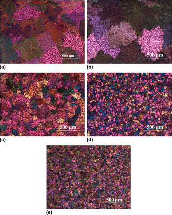
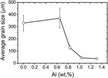
Figures 1 and 2 display the optical micrographs of the as-cast Mg–10Gd alloys with different Al additions and the relationship between Al content and the average grain size of Mg–10Gd alloys, respectively. At 0% and 0.65% Al additions, the grains are either equiaxed or columnar dendritic [Figs. 1(a) and 1(b)], and the grain size was ∼330 and 370 μm, respectively, with error bars that overlap. When the addition of Al was increased to 0.8%, the grain morphology changes to be fully equiaxed dendritic [Fig. 1(c)], and the grain size is greatly refined to 130 μm. As the Al content was further increased to 1% and 1.3%, the grains become spherical [Figs. 1(d) and 1(e)], and the grain size reduces to 44 and 37 μm, respectively. The effect of Al on the grain morphology and size of the Mg–10Gd alloy is quite similar to that of a Mg–10Y binary alloy.Reference Qiu, Zhang, Taylor and Kelly12
Optical micrographs showing grain structure in Mg–10Gd alloys with (a) 0%, (b) 0.65%, (c) 0.8%, (d) 1%, and (e) 1.3% Al additions.

Variation in grain size as a function of Al addition in Mg–10Gd alloys.

B. Identification of Al2Gd as active nucleant particles
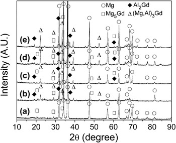
Figure 3 shows the XRD patterns of the as-cast Mg–10Gd alloys with different Al additions. The spectrum of the Mg–10Gd-based alloy [Fig. 3(a)] consists of only α-Mg and Mg5Gd. Extra peaks were observed in the spectra of the alloys with Al additions [Figs. 3(b)–3(e)]. Some of the peaks were indexed as Al2Gd, and the others are considered to be from the (Mg,Al)3Gd phase, which was also observed in Mg–2Al–1Zn–xGd alloys.Reference Wang, Du, Liu, Wang and Li14
XRD patterns of as-cast Mg–10Gd alloys with (a) 0%, (b) 0.65%, (c) 0.8%, (d) 1%, and (e) 1.3% Al additions.

Figure 4 shows the SEM images of the as-cast Mg–10Gd-based alloys with different Al additions. EDX analysis was used to help to identify what kind of phases the particles distributed in the alloys are. In addition to α-Mg, an irregular-shaped phase Mg5Gd and some tiny particles were observed in the Mg–10Gd-based alloy [Fig. 4(a)]. Mg5Gd is mainly distributed within the interdendritic regions. The tiny particle is rich in Gd (54.01%) and considered to be GdH2, which was previously observed in Mg–Gd binary alloys after mechanical polishing.Reference Peng, Huang, Meng, Li and Kainer20 All the samples in the present work were prepared by mechanical polishing as well, and it is considered that these GdH2 particles were formed during sample preparation.Reference Peng, Huang, Meng, Li and Kainer20 The addition of Al leads to the formation of a lamellar-like phase and polygonal particles, which are considered to be (Mg,Al)3Gd and Al2Gd, respectively.Reference Wang, Du, Liu, Wang and Li14 In the Mg–10Gd–0.65Al alloy, most of the polygonal particles are between 0.5 and 2 μm in size, with no particles observed at grain centers [Fig. 4(b)]. As the Al addition was increased to 0.8–1.3%, Al2Gd particles larger than 2 μm (marked by “+”) in size were reproducibly observed at grain centers [Figs. 4(c)–4(e)]. These Al2Gd particles at grain centers are possible active nucleant particles and might contribute to grain refinement. It should be noted that few polygonal particles in the alloy with 0.8% Al addition were formed and located at grain centers [Fig. 4(c)], particularly compared to the alloys with 1% and 1.3% Al additions [Figs. 4(d) and 4(e)]. It appears that the amount of the lamellar-like phase and both the number and size of Al2Gd particles increase with the increase of Al addition. The number densities and size distribution of the Al2Gd particles at grain centers will be shown in Sec. III. C. The morphology of the lamellar-like phase is shown in Fig. 4(f).
SEM images of Mg–10Gd alloys with (a) 0%, (b) 0.65%,(c) 0.8%, (d) 1%, (e) 1.3%, and (f) 1.3% Al additions. EDX analysis was used to help to identify what kind of phases the particles in the alloys are.

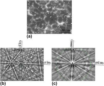
Since active nucleant particles are always crystallographically related to the metal matrix,Reference Qiu and Zhang21 the ORs between Al2Gd particles and α-Mg were identified to determine if they are active nucleant particles. Figure 5(a) shows a typical backscattered electron image of one particle located at a grain center in the Mg–10Gd–1Al alloy. The OR between the particle and the matrix was determined from the EBSD patterns [Figs. 5(b) and 5(c)]. The  $[112]_{{\rm{Al}}_{\rm{2}} {\rm{Gd}}} $ Kikuchi pole is very close to the
 $[2\bar 1\bar 10]_{{\rm{\alpha - Mg}}} $ pole, the
 $(1\bar 10)_{{\rm{Al}}_{\rm{2}} {\rm{Gd}}} $ Kikuchi band almost parallel to the
 $(0\bar 110)_{{\rm{\alpha - Mg}}} $ band, and the
 $(\bar 1\bar 11)_{{\rm{Al}}_{\rm{2}} {\rm{Gd}}} $ band is almost parallel to the
 $(0001)_{{\rm{\alpha - Mg}}} $band. Therefore, the OR can be expressed as:
 $$[112]_{{\rm{Al}}_{\rm{2}} {\rm{Gd}}} \,{\rm{‖}}\,[2\bar 1\bar 10]_{{\rm{\alpha - Mg}}} ,\,(1\bar 10)_{{\rm{Al}}_{\rm{2}} {\rm{Gd}}} \,{\rm{‖}}\,(0\bar 110)_{{\rm{\alpha - Mg}}} ,\,(\bar 1\bar 11)_{{\rm{Al}}_{\rm{2}} {\rm{Gd}}} \,{\rm{‖}}\,(0001)_{{\rm{\alpha - Mg}}}\quad .$$
Analysis of the orientation relationship between Al2Gd and α-Mg by EBSD: (a) SEM backscattered electron image of as-cast Mg–10Gd–1Al alloy showing an Al2Gd particle within an α-Mg grain (sample titled 70 degrees), (b) EBSD pattern from the Al2Gd particle [labeled as “+” in (a)] and (c) EBSD pattern from the surrounding α-Mg grain [labeled as “x” in (a)].

The ORs between another four particles near grain centers and their surrounding α-Mg were also observed, and the results are the same as the above one. No ORs were observed between either (Mg,Al)3Gd or Mg5Gd and α-Mg.
C. Number density and size distribution of possible active nucleant particles
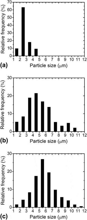
The number density of active nucleant particles affects the final grain size. More active nucleant particles indicate more heterogeneous nucleation occurring during solidification, leading to a smaller grain size. The number densities of possible active nucleant particles in the Mg–10Gd alloys with 0.85%, 1%, and 1.3% Al additions were calculated to be 8, 51, and 84 mm−2, respectively. Although it is uncertain whether all these particles are active nucleant particles, it is apparent that there are more active nucleant particles in the alloys with more Al additions. The size distribution of the possible active nucleation particles in these alloys is shown in Fig. 6. In the Mg–10Gd–0.8Al alloy, about 65% of the particles are between 2 and 3 μm in size [Fig. 6(a)]. However, as the addition of Al was increased to 1% and 1.3%, the size of most of these particles ranges from 2 to 7 μm, and many of the particles are larger than 3 μm in size [Figs. 6(b) and 6(c)]. Hence, increasing Al addition produces more large particles that are potential active nucleants, which was also found in a Mg–10Y binary alloy.Reference Qiu and Zhang21
Size distribution of the possible active Al2Gd nucleant particles in Mg–10Gd alloys with (a) 0.8%, (b) 1%, and (c) 1.3% Al additions.

D. Thermal stability of the fine grains in Mg–10Gd–1Al alloy
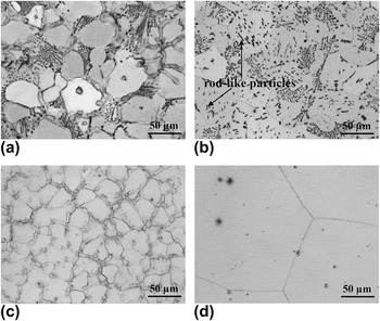
High thermal stability of fine grains can minimize the strength decrease with increasing temperature.Reference Qiu, Zhang, Taylor and Kelly12 Mg–10Gd–1Al and Mg–10Gd–1.3Al alloys were further solution treated at high temperature to investigate whether the fine grains produced by the addition of Al have high thermal stability. Similar results were obtained in both alloys, and the variation of the Mg–10Gd–1Al alloy after solution treatment was given as an example. The optical micrographs of the Mg–10Gd–1Al alloy before and after solution treatment at 550 °C for 48 h are shown in Figs. 7(a) and 7(b), respectively. The grain size was 47 ± 8.2 μm after solution treatment, which is statistically equivalent to that before solution treatment (44 ± 7.5 μm). For comparison, the optical micrographs of the Mg–10Gd–0.8Zr alloy before and after solution treatment at 550 °C for 48 h are shown in Figs. 7(c) and 7(d). The grain size of the as-cast Mg–10Gd–0.8Zr alloy was about 25 ± 3 μm, which is smaller than that of the as-cast Mg–10Gd–1Al alloy. However, after solution treatment, the grain size was increased dramatically to 217 ± 51 μm. It is evident that the thermal stability of the fine grains in the Mg–10Gd–1Al alloy is much better than those in the Mg–10Gd–0.8Zr alloy.
Optical micrographs showing grain coarsen tendency in Mg–10Gd–1Al alloy as compared with Mg–10Gd–0.8Zr alloy: (a) as-cast Mg–10Gd–1Al alloy, (b) solution-treated Mg–10Gd–1Al alloy, (c) as-cast Mg–10Gd–0.8Zr alloy, and (d) solution-treated Mg–10Gd–0.8Zr alloy. The solution treatment was carried out at 550 °C for 48 h. Rod-like particles were formed in Mg–10Gd–1Al alloy during solution treatment [shown in (b)].

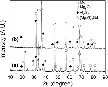
The XRD patterns of the Mg–10Gd–1Al alloy in the as-cast state and after solution treatment at 550 °C for 48 h are shown in Fig. 8. After solution treatment, peaks from both Mg5Gd and (Mg,Al)3Gd disappear, and only peaks from Al2Gd and α-Mg remain. It appears that the (Mg,Al)3Gd phase is not stable at 550 °C and the lamellar phase has transformed into Al2Gd particles but retaining the impression of the lamellar structure [Fig. 7(b)], and this phase is stable and did not decompose after prolonged exposure under the creep testing conditions of 200 °C and 50 MPa.Reference Wang, Du, Liu, Wang and Li14 It can also be seen that some rod-like particles are generated within grains during solution treatment of the Mg–10Gd–1Al alloy [Fig. 7(b)]. The structure of this phase still needs to be identified by transmission electron microscopy in future research, but according to the XRD result [Fig. 8(b)], they are likely to be Al2Gd particles.
XRD patterns of Mg–10Gd–1Al alloy: (a) as-cast and (b) solution treated at 550 °C for 48 h.

IV. DISCUSSION
A. Grain refinement mechanism
The addition of Al leads to not only good grain refinement but also excellent thermal stability of fine grains for the Mg–10Gd alloy. Hence, it is important to understand the related grain refinement mechanism of the stable fine grains.
First, it appears that Al2Gd particles larger than 2 μm in size need to be present in the melt before the formation of α-Mg and this occurs at Al concentrations at 0.8% and above. In other words, enough Al is required to form what appear to be peritectic particles, which are able to act as nucleation sites during solidification. It is well known that peritectic phases often promote grain refinement.Reference Crossley and Mondolfo22 Although Al2Gd particles are formed in the Mg–10Gd alloy with 0.65% Al addition [Fig. 3(b)], they are not at grain centers [Fig. 4(a)]. It appears that these particles in the Mg–10Gd–0.65Al alloy are formed after, rather than before, the formation of primary α-Mg and consequently are not available to be nucleant particles. An alternate explanation is that the particles are too small to be active nucleants at such compositions. The size distribution of particles will be discussed in Sec. IV. B.
Second, they must be effective nucleant particles. Crystallographic matching is a tool for identifying effective nucleating substrates, as good crystallographic matching is related to a low-energy coherent interface.Reference StJohn, Cao, Qian and Easton23 The edge-to-edge matching model has been used to predict the ORs between nucleant particles and the matrix with generally good correlation with experimental results.Reference Qiu, Zhang, Taylor and Kelly12, Reference Zhang, Kelly, Qian and Taylor24, Reference Qiu, Zhang, Fu, Kelly and Taylor25 The model has been described extensively previously.Reference Zhang, Kelly, Qian and Taylor24–Reference Zhang and Kelly26 Qiu et al.Reference Qiu, Zhang, Taylor and Kelly12 calculated the interatomic spacing misfit (f r) and the interplanar spacing mismatch (f d) between Al2Y and α-Mg. As Al2Gd and Al2Y have the same structure type (Cu2Mg) and similar lattice constants ( $a_{{\rm{Al}}_{\rm{2}} {\rm{Gd}}} $ = 0.790 nm and
 $a_{{\rm{Al}}_{\rm{2}} {\rm{Y}}} $ = 0.786 nm),Reference Villars and Calvert19 the lattice matching parameters can be easily updated for Al2Gd and α-Mg (Fig. 9). The values of f r and f d are demonstrated by the length of the black and gray bars. The superscripts S and Z mean straight and zigzag rows, respectively.
 $ \lt 112 > _{{\rm{Al}}_{\rm{2}} {\rm{Gd}}}^{\rm{S}} \,{\rm{|}}\, \lt 2\bar 1\bar 10 > _{{\rm{\alpha - Mg}}}^{\rm{S}} $ and
 $ \lt 110 > _{{\rm{Al}}_{\rm{2}} {\rm{Gd}}}^{\rm{Z}} \,{\rm{|}}\, \lt 10\bar 10 > _{{\rm{\alpha - Mg}}}^{\rm{Z}} $ have the same f r = 0.5%.
 $\{ 4\bar 40\} _{{\rm{Al}}_{\rm{2}} {\rm{Gd}}} \,{\rm{|}}\,\{ 0\bar 110\} _{{\rm{\alpha - Mg}}} $ has f d = 0.5%,
 $\{ \bar 311\} _{{\rm{Al}}_{\rm{2}} {\rm{Gd}}} \,{\rm{|}}\,\{ 0\bar 111\} _{{\rm{\alpha - Mg}}} $ has f d = 2.9%, and
 $\{ 4\bar 40\} _{{\rm{Al}}_{\rm{2}} {\rm{Gd}}} \,{\rm{|}}\,\{ 0002\} _{{\rm{\alpha - Mg}}} $ has f d = 7.2%, respectively. Double spacing of the plane
 $\{ 4\bar 40\} _{{\rm{Al}}_{\rm{2}} {\rm{Gd}}} $ was used to match the spacing of
 $\{ 0\bar 110\} _{{\rm{\alpha - Mg}}} $ and
 $\{ 0002\} _{{\rm{\alpha - Mg}}} $. Combining the matching row pairs with the plane pairs containing the matching rows results in two following ORs:
 $$ < 112 > _{{\rm{Al}}_{\rm{2}} {\rm{Gd}}} \,{\rm{‖}}\, < 2\bar 1\bar 10 > _{{\rm{\alpha - Mg}}} ,\,\{ 4\bar 40\} _{{\rm{Al}}_{\rm{2}} {\rm{Gd}}} \,{\rm{‖}}\,\{ 0\bar 110\} _{{\rm{\alpha - Mg}}} ,\,\{ \bar 311\} _{{\rm{Al}}_{\rm{2}} {\rm{Gd}}} \,{\rm{‖}}\,\{ 0\bar 111\} _{{\rm{\alpha - Mg}}}\quad ,$$
 $$ < 110 > _{{\rm{Al}}_{\rm{2}} {\rm{Gd}}} \,{\rm{‖}}\, < 10\bar 10 > _{{\rm{\alpha - Mg}}} ,\,\{ 4\bar 40\} _{{\rm{Al}}_{\rm{2}} {\rm{Gd}}} \,{\rm{‖}}\,\{ 0002\} _{{\rm{\alpha - Mg}}}\quad .$$
Interatomic spacing misfit along the close-packed row pairs and the interplanar spacing mismatch between the close-packed plane pairs of Al2Gd and α-Mg matrix. Dashed lines connect a pair of rows and a pair of planes containing this row pair. The plots were updated from Ref. 12. See the text for more details.

All the observed ORs between five active Al2Gd particles and their surrounding matrices are the same as the predicted OR(1). The predicted ORs have the same f r value, while OR(1) has a smaller f d value compared to OR(2). Furthermore, straight matching rows are always preferred over zigzag ones.Reference Qiu, Taylor and Zhang27 Therefore, OR(1) is more favorable than OR(2). Qiu et al.Reference Qiu, Zhang and Kelly28 examined the ORs between 40 possible active nucleation Al2Y particles and α-Mg, and both predicted ORs were observed between Al2Y and α-Mg. Whether OR(2) exists between Al2Gd and α-Mg requires further investigation.
B. Size distribution of possible nucleant particles
The free growth model proposed by Greer et al.Reference Greer, Bunn, Tronche, Evans and Bristow29–Reference Quested and Greer31 suggests that nucleation occurs first on the largest particles, at an undercooling inversely proportional to the particle diameter. Further nucleation on smaller particles is stifled by latent heat release. As shown in Fig. 6, most of the possible active particles are larger than 2 μm. That particles need to be large enough to act as nucleation sites has been evidenced by Greer and TroncheReference Greer, Bunn, Tronche, Evans and Bristow29, Reference Tronche and Greer30 who found that nucleation occurs only on the largest TiC particles, and QianReference Qian32 observed that most of the active Zr particles in a Mg sample are larger than 1 μm. Qiu and ZhangReference Qiu and Zhang21 also found that the Al2Y particles smaller than 2 μm do not act as heterogeneous nucleation sites. Hence, the size of the nucleants observed here agrees with previous investigation.
C. Thermal stability of fine grains
Previous research showed that due to the existence of stable particles along grain boundaries, the thermal stability of fine grains in the Mg–10Y–1Al alloy is much higher than that in the Mg–10Y–0.8Zr alloy.Reference Qiu, Zhang, Taylor and Kelly12Figure 4(a) shows that some particles exist along grain boundaries in the Mg–10Gd–1Al alloy as well. A lot of particles are still distributed along grain boundaries and throughout the matrix after solution treatment, as shown in Fig. 7(b). This indicates that the Al2Gd phase is thermally stable and survives the solution treatment, which is probably related to its high melting point of 1525 °C. The Al2Gd particles appear to suppress grain boundary migration, leading to the fine grains being retained at high temperatures. These Al2Gd particles are particularly important because no other as-cast intermetallics remain after solution treatment. The Zr particles, being less homogeneously distributed, as they do not reprecipitate as solid-state particles during solution treatment, are much less effective at pinning grain boundaries.
V. CONCLUSIONS
(i) The grain size of Mg–10Gd alloy is remarkably refined by the addition 0.8–1.3% Al. Al2Gd particles are formed and act as grain refining inoculants during solidification. One OR
 $[112]_{{\rm{Al}}_{\rm{2}} {\rm{Gd}}} \,{\rm{‖}}\,[2\bar 1\bar 10]_{{\rm{\alpha - Mg}}} ,\,(1\bar 10)_{{\rm{Al}}_{\rm{2}} {\rm{Gd}}} \,{\rm{‖}}\,(0\bar 110)_{{\rm{\alpha - Mg}}} $ was reproducibly observed between Al2Gd and α-Mg.
(ii) The number density of Al2Gd particles at grain centers in the Mg–10Gd–1.3Al alloy is higher than those in the Mg–10Gd–1Al alloy. Most of the particles at grain centers were between 2 and 7 μm in size.
(iii) After 48 h solution treatment at 550 °C, the grain size in the Mg–10Gd–1Al alloy does not coarsen. The thermal stability of the fine grains in the Mg–10Gd–1Al alloy is much higher than those in the Mg–10Gd–0.8Zr alloy. Al2Gd particles survived the solution treatment, and it appears that they restricted grain coarsening.

ACKNOWLEDGMENTS
The work is sponsored by National natural science foundation of China (No. 51275295), CAST Cooperative Research Centre of Australia, and Technological innovation projects of Shanghai aerospace advanced technology Joint Research Centre (No. USCAST2012-1-15). The authors acknowledge Monash Centre for Electron Microscopy (MCEM) for access to experimental facilities.