Introduction
Gel electrophoresis in a gel matrix has proved to be a powerful approach in providing relative angular information about helical disposition in branched double-stranded nucleic acids such as helical junctions. In many cases, this has effectively provided a good description of the symmetry and three-dimensional shape of these species. The method is quite simple and requires inexpensive apparatus but has scored many notable successes in nucleic acid structure, sometimes a decade ahead of crystallography. These include the determination of the structures of the Holliday junction in DNA, and more recently its complexes with resolving enzymes, and RNA species such as the hammerhead and hairpin ribozymes. In all cases the conclusions from comparative gel electrophoresis have been confirmed by other structural or biophysical techniques. Moreover, given that the forces involved are low and that the gel matrix typically contains at least 90% water, electrophoresis can be regarded as a non-perturbing solution method.
Yet despite its proven successes, this approach has not been widely adopted in many laboratories. Perhaps one reason for this is that the method is not underpinned by a good theoretical understanding compared with other structural methods. This means that many of the conclusions that result from comparative gel electrophoresis are not quantitative. The symmetry of a given junction may be determined, but inter-axial angles will not be measured beyond learning which are larger or smaller than others. However, that information may well be enough to provide a good description of the structure. In the case of the Holliday junction for example, the electrophoretic approach provided sufficient information to determine the essential structural features of the anti-parallel stacked X structure.
This review aims to explain how comparative gel electrophoresis can be applied to structural problems in branched DNA and RNA species and to evaluate its performance in a number of different systems. A number of recent crystallographic structures have provided a basis for evaluating the success rate of the electrophoretic approach, and thus it is useful to review the performance at this time.
2. Theory
Most attempts to provide a theoretical treatment of the gel electrophoresis of DNA molecules have been based around de Gennes' (Reference De Gennes1971) concept of reptation. The migration of the nucleic acid is considered to be constrained by a ‘tube’ formed by the polymer matrix of the gel, and the DNA migrates along the tube in the manner of a snake. There is a balance of forces between the electric field that is pulling the DNA through the gel and the retardation due to frictional forces between the DNA and the matrix.
A simple but quite successful theory based on this idea was provided by Lumpkin & Zimm (Reference Lumpkin and Zimm1982), who derived the equation of motion of the nucleic acid along a gel tube as:

where μ is the mobility of the nucleic acid chain, Q is the effective charge, ξ is the frictional coefficient, h x is the end-to-end length in the direction of the electric field and L is the contour length. This indicates that if a double-stranded DNA or RNA molecule becomes kinked (thus reducing the end-to-end distance), its electrophoretic mobility will be retarded. There have been various refinements to the theory (Lerman & Frisch, Reference Lerman and Frisch1982; Lumpkin et al. Reference Lumpkin, Dejardin and Zimm1985, Reference Lumpkin, Levene and Zimm1989; Levene & Zimm, Reference Levene and Zimm1989; Duke et al. Reference Duke, Semenov and Viovy1992; Barkema et al. Reference Barkema, Marko and Widom1994), for example to include the elasticity of the nucleic acid (Deutsch, Reference Deutsch1988), but the simple Lumpkin–Zimm theory works well for kinked nucleic acids. However, there is no well-developed theory at present for nucleic acids containing branchpoints such as three- or four-way junctions, although there have been recent attempts to move in this direction (Heuer et al. Reference Heuer, Yuan, Saha and Archer2005; Saha et al. Reference Saha, Heuer and Archer2006). Most electrophoretic data on junctions are analysed empirically, and the rule that increased kinking results in lower mobility has worked almost every time. Moreover, the essence of the comparative approach is that the conclusions result from the interpretation of relative mobilities of matched species.
3. Bends and kinks in duplex nucleic acids
The simplest conformational properties in nucleic acids to be studied by comparative gel electrophoresis are duplexes containing a kink of some type. These lead to a retardation of electrophoretic mobility that can often be treated semi-empirically using the Lumpkin–Zimm theory (Lumpkin & Zimm, Reference Lumpkin and Zimm1982). Interruptions to the basepairing of a helix by internal loops can be regarded as the simplest type of branchpoint and is sometimes referred to as a two-way helical junction.
3.1 A-tract bent DNA
One of the first systems to be studied in this manner was the DNA of kinetoplast mini-circles, which contain phased oligoadenine sequences (Challberg & Englund, Reference Challberg and Englund1980; Marini et al. Reference Marini, Levene, Crothers and Englund1982). These molecules are fully basepaired and cannot be regarded as in any sense branched. Nevertheless, this provides a useful starting point because it was probably the first system in which deviation from a straight helical geometry was found to result in a pronounced reduction in electrophoretic mobility. In a classical experiment, Wu & Crothers (Reference Wu and Crothers1984) showed that restriction fragments containing the kinetoplast bending locus exhibited marked retardation of electrophoretic mobility in polyacrylamide gels and that the effect was greatest as the bending sequence became more centrally located. The global distortion of the DNA structure was supported by electric birefringence measurements (Hagerman, Reference Hagerman1984). The extent of the electrophoretic retardation was affected by temperature and the ionic composition of the medium (Diekmann & Wang, Reference Diekmann and Wang1985), and in general terms, the electrophoretic mobility is reasonably well described using the Lumpkin–Zimm theory (Drak & Crothers, Reference Drak and Crothers1991).
3.2 Base bulges in DNA and RNA
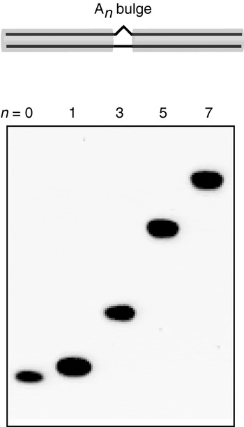
Base bulges, or asymmetric internal loops, introduce a discrete discontinuity into the helix of double-stranded DNA or RNA, generating a pronounced kinking of the axis. This is readily studied by the consequent retardation of electrophoretic mobility relative to the equivalent duplex in which the bulge or loop is replaced by fully basepaired duplex (Bhattacharyya & Lilley, Reference Bhattacharyya and Lilley1989; Rice & Crothers, Reference Rice and Crothers1989; Bhattacharyya et al. Reference Bhattacharyya, Murchie and Lilley1990; Wang & Griffith, Reference Wang and Griffith1991; Riordan et al. Reference Riordan, Bhattacharyya, Mcateer and Lilley1992; Zacharias & Hagerman, Reference Zacharias and Hagerman1995b; Luebke & Tinoco, Reference Luebke and Tinoco1996) (Fig. 1). In general, it was found that the extent of retardation was dependent upon the number and type of nucleotides present in the bulge, with the effect of oligopurine bulges being greater than that of oligopyrimidines and the mobility as a function of bulge size has been fitted to a variety of empirical functions in different studies. The conformational properties of nucleotide bulges have been confirmed using a variety of biophysical methods, including fluorescence resonance energy transfer (FRET) (Gohlke et al. Reference Gohlke, Murchie, Lilley and Clegg1994), cryoelectron microscopy (Lilley, Reference Lilley1995) and hydrodynamic methods (Zacharias & Hagerman, Reference Zacharias and Hagerman1995a, Reference Zacharias and Hagermanb). These approaches have provided estimates for the extent of axial bending as a function of the bulge size and composition in DNA and RNA. For example, using FRET between terminally attached fluorophores on 18-bp DNA duplexes, we estimated that an A5 bulge introduced an angular distortion of 95±10° (Gohlke et al. Reference Gohlke, Murchie, Lilley and Clegg1994) and that RNA and DNA were kinked to similar extents. Note that bend angles given here are expressed as the deviation from linearity, i.e. 180° −α, where α is the included angle at the kink. Zacharias & Hagerman (Reference Zacharias and Hagerman1995b) analysed a series of bulged RNA duplexes using transient electric birefringence, fitting the decay curves to worm-like chain behaviour. They then found that the electrophoretic mobility of these species (μrel) could be fitted to a quadratic function of the form:

where θ is the estimated bend angle and b is an adjustable parameter. In this analysis, an RNA duplex containing an A5 bulge was found to be bent by 75±3°. Luebke & Tinoco (Reference Luebke and Tinoco1996) analysed the electrophoretic mobility of a series of An-bulged DNA duplexes, where the context was derived from that of a bulge present in the Tetrahymena group I intron. Using the bend angles from the transient electric birefringence study (Zacharias & Hagerman, Reference Zacharias and Hagerman1995b), they fitted their data using an empirical relationship of the form:

where the parameters have the same meaning as above. From this analysis, they estimated a bend angle of 69° for the natural A5 bulge of the group I intron RNA.
Retarded electrophoretic migration of DNA duplexes containing central base bulges as a function of bulge size. The species are duplexes of fixed length (40 bp) with unopposed additional adenine nucleotides (i.e. the bulge) located in the centre. These have been electrophoresed in parallel in a 15% polyacrylamide gel in 90 mm Tris–borate (pH 8·3) and 1 mm EDTA. The left species is a perfect duplex, followed by the same duplex with central oligoadenine bulges of 1, 3, 5 or 7 nt as indicated. The species exhibit retarded mobility due to the presence of the bulges, consistent with a kinking of the helix. The retardation increases with the size of the bulge, suggesting a greater degree of kinking.

In general, it is true that bulges kink DNA and RNA duplexes, and that the greater the size of the bulge, the greater the kinking and hence the larger the electrophoretic retardation of the molecule. For example, a series of 27-bp DNA duplexes containing An bulges, where n=0–11, exhibited progressively lower electrophoretic mobility in a 15% polyacrylamide gel with n across the entire series (Gohlke et al. Reference Gohlke, Murchie, Lilley and Clegg1994). While there is no well-developed theory that will accurately predict the mobility of such molecules, the relative mobility is reasonably well accounted for by the simple Lumpkin–Zimm theory. However, it may not be appropriate to extend this to more elaborate species with complex tertiary interactions. For example, the P4–P6 domain of the Tetrahymena group I intron comprises two long domains (those of P5abc and P5–P4–P6) running side by side, associated via a hinge point (the J5/5a junction) in the centre (Cate et al. Reference Cate, Gooding, Podell, Zhou, Golden, Kundrot, Cech and Doudna1996). To a first approximation, this bears some resemblance to a kinked helix, yet it exhibits fast electrophoretic mobility (Silverman & Cech, Reference Silverman and Cech1999). It seems probable that the multiple tertiary interactions between the two domains, including A-minor and the loop–receptor interaction, generate a stable, compact fold with faster mobility in the gel.
3.3 The kink-turn in RNA
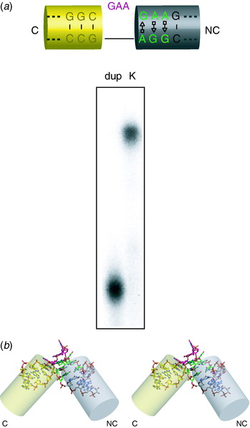
The kink-turn (k-turn) is a special case of a bulged RNA, first identified by inspection of crystal structures of ribosomal subunits (Klein et al. Reference Klein, Schmeing, Moore and Steitz2001). It comprises a (usually three-) base bulge followed by A⋅G and G⋅A pairs and frequently a third non-Watson–Crick pair (Fig. 2). It was noted that these generated an extreme kinking of the axis with an included angle of ~60°, stabilised by A-minor interactions. Not surprisingly then, this was found to result in a marked retardation of electrophoretic mobility in polyacrylamide gels (Goody et al. Reference Goody, Melcher, Norman and Lilley2003; Matsumura et al. Reference Matsumura, Ikawa and Inoue2003). However, the finding that the retardation (i.e. the tight kinking of the RNA) required the presence of metal ions was not expected. Electrophoretic mobility, coupled with FRET studies, revealed tight sequence requirements for the formation of the k-turn. This could be extended to the level of single hydrogen bonds; removal of certain critical 2′-OH groups completely prevented folding into the kinked conformation (Liu & Lilley, Reference Liu and Lilley2007).
Electrophoretic retardation of RNA containing a k-turn sequence. The sequence shown is that of Kt-7 (Klein et al. Reference Klein, Schmeing, Moore and Steitz2001). (a) Electrophoretic analysis. A chemically synthesised 65-bp duplex comprised a 20-bp RNA section containing the Kt-7 sequence flanked by outer DNA sections. For comparison, a duplex species lacking the bulge and with the A⋅G pairs changed to Watson–Crick base pairs was made. Radioactively labelled k-turn species (K) and its corresponding duplex (dup) were electrophoresed in 15% polyacrylamide in 90 mm Tris–borate (pH 8·3) and 500 μm Mg2+ and phosphorimaged. Note the pronounced retardation resulting from the presence of the k-turn motif in the RNA. (b) Parallel-eye stereoscopic view of the structure of the k-turn in the crystal. The structure shown is the box C/D k-turn (Moore et al. Reference Moore, Zhang, Fenley and Li2004). The helical arms are extended by the transparent cylinders, to highlight the strongly kinked trajectory. The yellow cylinder is the arm with conventional Watson–Crick basepairing (C), while the grey cylinder is that with the A⋅G pairs (NC). The image was generated using PyMol from the coordinate file 1rlgbu.pdb.

3.4 Kinking of DNA by chemical adduct formation
Axial kinking of DNA can also be generated via adduct formation by the nucleobases. As an example, Husain et al. (Reference Husain, Griffith and Sancar1988) showed that the introduction of a thymine photodimer into double-stranded DNA results in anomalously slow electrophoretic mobility due to the formation of a ~30° kink. Similarly, it was shown that a cis-platinum interstrand adduct at a GpC site within a DNA fragment led to a marked reduction of electrophoretic mobility (Sip et al. Reference Sip, Schwartz, Vovelle, Ptak and Leng1992).
3.5 Multiple bends and dihedral angles: phasing experiments by electrophoresis
While a single kink will introduce a planar bend into a duplex, two such kinks will generate a three-dimensional trajectory of the molecule. Perhaps one of the first examples of this type of property was shown with A-tract bends in DNA (Drak & Crothers, Reference Drak and Crothers1991). But this behaviour will be exhibited by any feature that generates axial kinking, including bulges and junctions. Two axial kinks will be related by a dihedral angle, which will be a function of the local geometry of the kinks, i.e. the direction of the bend that is produced, and the spacing between the two kinks and the periodicity of the helix. Thus the shape of the molecule, and hence its frictional properties and consequent electrophoretic mobility, will vary systematically with the length of the helix between the kinks. In these experiments (sometimes termed ‘phasing experiments’ as a kind of shorthand), the overall length of the duplex is normally kept constant by removing base pairs from the arms as the spacer is lengthened. The end-to-end distance will vary sinusoidally as the inter-kink helix length is varied, generating fastest mobility when the structure is trans-planar and slowest for the cis-planar form. The variation in mobility will be a progressively damped sine function, with a period equivalent to that of the spacer helix and a phase determined by the structure of the kinks.
3.5.1 Two bulge kinks and the measurement of helix periodicity
Perhaps the simplest two-kink system is a DNA or RNA duplex with two bulges. These generate the expected sinusoidally modulated electrophoretic mobility as a function of the length of helix between the bulges. Such experiments provided the first measurements of the periodicity of RNA (Bhattacharyya et al. Reference Bhattacharyya, Murchie and Lilley1990; Tang & Draper, Reference Tang and Draper1990, Reference Tang and Draper1994). The sinusoidal mobility variation demonstrates that the kinks have a particular direction and provides a more sensitive means of revealing axial kinking when the extent of deviation is small. Figure 3a presents an example of this, where one of the bulges is a highly asymmetric internal loop of a U1A box motif.
Electrophoretic experiments to test the phase relationship between two structures that generate kinking. Two kinks will generate a dihedral angle between the outer arms that depends on the number of base pairs in the helix between them. In such experiments, one kink is generally (but not always) a base bulge, while the other can be a bulge, a loop or a junction. Modulation of the electrophoretic mobility as a function of central helix length (n) indicates that the kink examined has a definite direction, which can be inferred from the phase. (a) The asymmetric internal loop of the U1A mRNA UTR box 2 (Grainger et al. Reference Grainger, Murchie, Norman and Lilley1997). The box 2 loop comprises a single adenine opposing seven nucleotides on the opposite strand and exhibits marked electrophoretic retardation when contained as a single motif in duplex RNA. In this experiment, it has been placed in a 67-bp duplex, separated from an A5 bulge by a spacer sequence 3–21 bp in length. These species were electrophoresed in 15% polyacrylamide, revealing a pronounced modulation of mobility with spacing. The mobility has been plotted against spacer length and fitted to a model based upon the Lumpkin–Zimm theory assuming bends of fixed angle and dihedral angle for both the A5 bulge and the U1A box 2. (b) The four-way junction of the hairpin ribozyme (Goody et al. Reference Goody, Lilley and Norman2004). The ribozyme junction was combined with an A4 bulge with a variable length spacer of 8–22 bp between them. These were electrophoresed in a 10% polyacrylamide gel in the presence of 5 mm Mg2+ ions at 20°C.

3.5.2 One bulge kink and a k-turn
A k-turn is an extreme form of a bulge kink in RNA, and unsurprisingly, duplexes with one bulge and one k-turn exhibit electrophoretic mobility that varies with the spacing between the two kinks (Goody et al. Reference Goody, Melcher, Norman and Lilley2003). However, the acute included angle of the k-turn results in anomalous behaviour for some specific spacer lengths; species that would be close to a planar cis form apparently deform their dihedral angle to avoid a clash between the terminal helices of the duplex, generating faster mobility.
3.5.3 One bulge kink and a helical junction
Another means in which a kink can be introduced into the axis of a duplex is by the presence of a helical junction (see Section 4). An example of this is provided by an electrophoretic study of the four-way RNA junction of the hairpin ribozyme (Goody et al. Reference Goody, Lilley and Norman2004). The construct can be viewed as a junction with two long and two short arms, where one of the long arms contains a bulge kink at a distance from the junction that is systematically varied. Once again, this generates a sinusoidally modulated electrophoretic mobility (Fig. 3b), as the dihedral angle between the long arms extending from the bulge and the junction varies. Using this approach, we were able to deduce the handedness of the hairpin ribozyme junction (Goody et al. Reference Goody, Lilley and Norman2004). This application of the method requires some prior knowledge of the structure of the junction, so that the spacer helix and the remaining long helix are not coaxially stacked in the predominant form of the junction.
3.5.4 Two helical junctions
Finally, two helical junctions may be linked through a common helix, the length of which is then varied. If one of the remaining arms is significantly longer than the other(s), then the dihedral angle between those arms will vary with the length of the linking helix. This approach was used to measure the dihedral angle between arms projecting away from the two three-way RNA junctions of the VS ribozyme (Lafontaine et al. Reference Lafontaine, Norman and Lilley2002; described later).
4. DNA junctions
Helical branchpoints are created where three or more helices radiate from a centre, connected by the covalent continuity of their component strands (Lilley, Reference Lilley2000). Perhaps the most well known of these is the four-way (Holliday) junction in DNA. Junctions can be perfectly basepaired or elaborated by additional formally-unpaired bases at the point of strand exchange; these can be classified by a standard nomenclature (Lilley et al. Reference Lilley, Clegg, Diekmann, Seeman, von Kitzing and Hagerman1995), according to which the simple four-way junction is 4H.
4.1 The principle of the long–short arm method
The power of gel electrophoresis to report on the angular distribution of helical arms in a four-way junction was first demonstrated in a pseudo-cruciform structure (Gough & Lilley, Reference Gough and Lilley1985). This showed that placing a four-way junction within a linear DNA fragment led to a marked reduction in electrophoretic mobility, which was greater the more centrally located the junction. The electrophoretic retardation suggested that the DNA fragment was effectively kinked by the presence of the junction due to the angular direction of the two long arms. This approach was then extended to compare the angles subtended between all the helical pairs of a given junction (Cooper & Hagerman, Reference Cooper and Hagerman1987; Duckett et al. Reference Duckett, Murchie, Diekmann, von Kitzing, Kemper and Lilley1988). In a junction with n helical arms, there are nC 2 combinations of the arms taken two at a time, where

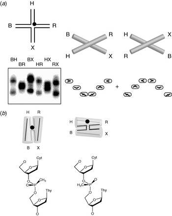
Thus the basis of the long–short arm method is to compare the electrophoretic mobility of the nC 2 species with two long (typically 40 bp) arms and the remaining arms short (e.g. 15 bp). For a four-way junction (4H, where n=4), there are six species to compare, each of which has two long and two short arms. A three-way junction (3H, n=3) gives three species, each of which has a single short arm. The symmetry and pattern of the mobilities of the different species turn out to be highly informative on the global shape of the junction.
There are a variety of ways to generate the long–short arm species. Cooper & Hagerman (Reference Cooper and Hagerman1987) first devised an approach where extension arms were ligated to two arms of the core of a four-way junction in the six combinations, observing differences in the resulting mobilities showing that the symmetry was lower than tetrahedral. By contrast, Duckett et al. (Reference Duckett, Murchie, Diekmann, von Kitzing, Kemper and Lilley1988) assembled DNA four-way (4H) junctions from four oligonucleotides each of 80 bp (four arms of 40 bp). Each arm had a unique restriction site located about 12 bp from the centre, by means of which any arm could be shortened by digestion with its appropriate enzyme. These were BamHI, HindIII, EcoRI and XbaI, from which the arms were named B, H, R and X. These labels have survived much longer than the original approach; with the ease and economy of modern DNA synthesis, it is now much easier to synthesise the 16 required oligonucleotides and then simply assemble the six long–short arm species by hybridisation of the required four oligonucleotides for each. Arm lengths of 40 bp are a trade-off between resolution and synthetic convenience. Longer arms can achieve superior separation of species but require synthesis of correspondingly longer oligonucleotides.
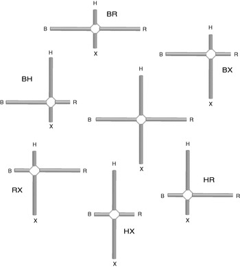
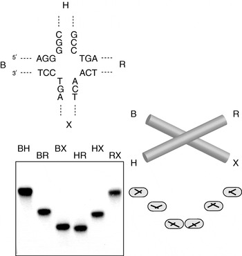
The approach can be illustrated for the four-way DNA junction (Fig. 4). To begin with, let us assume that the structure is that of an open X shape, where each of the arms is extended towards the corners of a square. We generate the six long–short arm species and name them according to the long arms, so that species BH has long B and H arms and short R and X arms for example. We note that two quite different classes of species have been generated, depending on whether the long arms are adjacent (BH, BX, HR and RX) or diametrically opposed (BR and HX) around the junction. We now electrophorese the six species in an 8% or 10% polyacrylamide gel (giving significantly better resolution than the original studies in which 5% gels were used; Duckett et al. Reference Duckett, Murchie, Diekmann, von Kitzing, Kemper and Lilley1988), loaded in the order BH, BR, BX, HR, HX and RX. On the basis of previous studies on kinked DNA molecules, we might expect that the quasi-linear species (BR and HX) would migrate faster than the remaining four species, leading to a pattern of mobilities described by slow–fast–slow–slow–fast–slow. In fact, that is exactly what is observed when four-way DNA junctions are studied in the absence of added metal ions as discussed in the next section. On the other hand, if the junction folds into an alternative structure, a different pattern of mobility is expected. Note that very few assumptions go into the interpretation. All the conclusions are drawn from the relative mobilities of the multiple long–short arm species, and no calibration against other species is required.
The principle of the long–short arm method for the electrophoretic analysis of a four-way junction. The six species can be considered to be derived from the central junction comprising four long arms (e.g. 40 bp). These are sequentially named B, H, R and X as in our original studies on DNA junctions (Duckett et al. Reference Duckett, Murchie, Diekmann, von Kitzing, Kemper and Lilley1988). The long–short arm species are generated by shortening two helical arms, to give the six species shown, named by their long arms.

4.2 The four-way DNA junction in the absence of metal ions
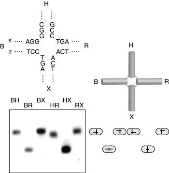
Perhaps the simplest pattern of mobilities is found when a four-way junction (4H) is analysed in the absence of metal ions; for such an experiment, the electrophoresis buffer would generally include some EDTA to ensure that any traces of metal ions are chelated. The observed pattern (Fig. 5) is slow–fast–slow–slow–fast–slow, which is exactly what was predicted earlier for the extended square structure. Thus it was concluded that in the absence of added metal ions, the centre of the junction remained open (Duckett et al. Reference Duckett, Murchie, Diekmann, von Kitzing, Kemper and Lilley1988), consistent with the reactivity of thymine bases at the point of strand exchange to electrophilic attack. Confirmation of the square structure in the absence of metal ions was provided by subsequent FRET studies (Murchie et al. Reference Murchie, Clegg, von Kitzing, Duckett, Diekmann and Lilley1989; Clegg et al. Reference Clegg, Murchie, Zechel, Carlberg, Diekmann and Lilley1992, Reference Clegg, Murchie, Zechel and Lilley1994). There is no crystal structure of a four-way junction in isolation in the extended structure, although there are protein complexes of junctions in this form (discussed later).
Comparative gel electrophoresis of a four-way DNA junction in the absence of added metal ions. The six radioactively labelled long–short arm species of junction 3 (with the central sequence shown) (Duckett et al. Reference Duckett, Murchie, Diekmann, von Kitzing, Kemper and Lilley1988) were electrophoresed in an 8% polyacrylamide gel in 90 mm Tris–borate (pH 8·3) and 1 mm EDTA. The slow–fast–slow–slow–fast–slow pattern of mobility is interpreted in terms of the extended square structure shown, giving the four species with 90° angles subtended between the long arms (slow species) and two with 180° angles (fast species). The interpretation is indicated by the schematics adjacent to the gel in this and subsequent figures.

4.3 The four-way DNA junction in the presence of divalent metal ions: the stacked X structure
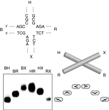
The electrophoretic pattern of the six long–short arm species was found to change significantly upon addition of Mg2+ ions (Duckett et al. Reference Duckett, Murchie, Diekmann, von Kitzing, Kemper and Lilley1988). An example for the well-studied sequence junction 3 is shown in Fig. 6. Instead of two types of species, there are now three, and the pattern may now be described at slow–intermediate–fast–fast–intermediate–slow – like a smile. This indicates that the six inter-helical angles fall into three classes and that the symmetry has been lowered from the square structure. The pattern may be explained by the formation of the stacked X structure, formed by coaxial helical alignment of helices in pairs (B with X and H with R in this case, although an alternative conformer of this structure is possible, discussed later) and a rotation between the two axes.
Comparative gel electrophoresis of a four-way DNA junction in the presence of metal ions. The six radioactively-labelled long–short arm species of junction 3 (Duckett et al. Reference Duckett, Murchie, Diekmann, von Kitzing, Kemper and Lilley1988) were electrophoresed in a 10% polyacrylamide gel in 90 mm Tris–borate (pH 8·3) and 100 μm Mg2+. The pattern is quite different from that of the same species in the absence of metal ions (compare with Fig. 5), being slow–intermediate–fast–fast–intermediate–slow. This is interpreted in terms of the stacked X structure, giving two species with acute angles between the long arms (slow), two with obtuse angles (intermediate) and two with collinear long arms (fast).

A further feature of the structure emerged from the electrophoretic analysis, which came as a surprise to many. The lowering of symmetry to a twofold symmetric structure divides the strands into two types: continuous strands that run down the length of the axes and the exchanging strands that change axes at the junction. It had long been assumed that the structure would be parallel, i.e. that the continuous strands would run in approximately the same direction. However, a required conclusion from the electrophoretic data was that the structure was anti-parallel, so that the exchanging strands did not cross at the centre. A parallel structure would give a predicted pattern of intermediate–slow–fast–fast–slow–intermediate for junction 3, which is quite different from that found experimentally. The parallel structure had been drawn in many textbooks, and some geneticists found an anti-parallel structure hard to accept, preferring to question the interpretation of the electrophoretic data.
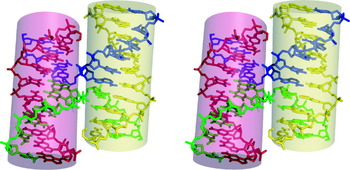
Analysis of the structure by FRET (Murchie et al. Reference Murchie, Clegg, von Kitzing, Duckett, Diekmann and Lilley1989; Clegg et al. Reference Clegg, Murchie, Zechel, Carlberg, Diekmann and Lilley1992) and hydrodynamic methods (Cooper & Hagerman, Reference Cooper and Hagerman1989) soon confirmed the anti-parallel stacked X structure in solution, and stereochemically acceptable models of the structure were built (von Kitzing et al. Reference Von Kitzing, Lilley and Diekmann1990). However, we had to wait many years until the structure was confirmed by X-ray crystallography. Despite numerous attempts, the four-way DNA junction resisted all efforts at crystallisation. Ironically, a series of structures were finally obtained at the turn of the millennium, none of which had been the intended target of crystallisation. All three confirmed the broad details of the anti-parallel stacked X structure. The first was a DNA–RNA hybrid in which one of the stacked helical pairs was A-form in geometry (Nowakowski et al. Reference Nowakowski, Shim, Prasad, Stout and Joyce1999). The second was an all-DNA structure, which contained a number of non-Watson–Crick base pairs (Ortiz-Lombardía et al. Reference Ortiz-Lombardía, González, Erijta, Aymamí, Azorín and Coll1999). Finally, the structure of a perfectly paired, all-DNA four-way structure was presented by Ho and co-workers (Eichman et al. Reference Eichman, Vargason, Mooers and Ho2000) (shown in Fig. 7). We see that the structure has all the expected features of the stacked X structure, with perfect coaxial stacking of helices and an anti-parallel conformation. Of course, the atomic resolution structures provide a wealth of new details about the structure, which could not be obtained from lower-resolution approaches, but the important overall structure was successfully solved by comparative gel electrophoresis, and more than a decade sooner.
Parallel-eye stereoscopic view of the structure of a four-way DNA junction from X-ray crystallography (Eichman et al. Reference Eichman, Vargason, Mooers and Ho2000). The four strands are differentiated by colour. The image was generated from the coordinate file 1dcw.pdb.

4.4 Alternative stacking conformers of the four-way junction
In principle there are two alternative forms of the stacked X structure, differing in the choice of stacking partners. So staying with the four arms B, H, R and X, we could fold the structure by the coaxial stacking of arms B on H (termed isoI), or arms X on B (isoII). The resulting conformers are stereochemically exactly equivalent; they differ only in terms of which helices are coaxially stacked. The relative stabilities of the two conformers would be expected to be determined by sequence-specific interactions at the point of strand exchange. Junction 3 evidently has a bias towards the isoII conformer in which X stacks on B (and therefore R on H, of course), as seen in Fig. 6. If the alternative stacking conformer predominated, the predicted electrophoretic pattern would still comprise two fast, two intermediate and two slow species, but would be upside-down compared with that seen for junction 3, i.e. the ‘smile’ pattern would be replaced by a ‘sad face’.
In our first electrophoretic studies on four-way DNA junctions, we did indeed observe both types of pattern for different sequence junctions in the presence of magnesium ions and interpreted these in terms of the two forms of the stacked X structure with alternative stacking partner choice (Duckett et al. Reference Duckett, Murchie, Diekmann, von Kitzing, Kemper and Lilley1988) (Fig. 8). Subsequent FRET analysis of the same junctions confirmed this interpretation (Murchie et al. Reference Murchie, Clegg, von Kitzing, Duckett, Diekmann and Lilley1989; Clegg et al. Reference Clegg, Murchie, Zechel, Carlberg, Diekmann and Lilley1992).
Alternative conformer formation by changing the central sequence of a four-way DNA junction demonstrated by comparative gel electrophoresis. Junction 1 differs from junction 3 (shown in Fig. 6) only by the reversal of the four base pairs flanking the point of strand exchange (Duckett et al. Reference Duckett, Murchie, Diekmann, von Kitzing, Kemper and Lilley1988). Yet this small change results in the inversion of the mobility pattern for the six long–short arm species, to give fast–intermediate–slow–slow–intermediate–fast. This is interpreted in terms of the same stacked X structure, except that the helical stacking partners have been exchanged.

4.5 Dynamics of conformer exchange
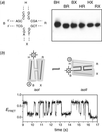
The existence of alternative stacking conformers raises two questions: First, are they in dynamic exchange for a given junction molecule? Second, how strong is the bias towards one specific conformer? Enzymatic (Murchie et al. Reference Murchie, Portugal and Lilley1991) and nuclear magnetic resonance (NMR) (Miick et al. Reference Miick, Fee, Millar and Chazin1997) experiments pointed towards a dynamic exchange between stacking conformers in solution. Comparative gel electrophoresis of one junction in particular was of special interest. Junction 7 gave an electrophoretic pattern in which all six long–short arm species had virtually equal mobility (Grainger et al. Reference Grainger, Murchie and Lilley1998) (Fig. 9a). This pattern has never been observed before and requires a new explanation. It would, of course, be consistent with a tetrahedral disposition of the four arms, yet that is rather improbable structurally. A more plausible hypothesis is that the two stacking conformers are equally populated and in rapid exchange compared with the rate of equilibration in the gel pores.
Dynamic exchange of stacking conformers in a DNA junction. Junction 7 is identical to junctions 1 and 3 except for the four base pairs flanking the point of strand exchange (Grainger et al. Reference Grainger, Murchie and Lilley1998). (a) Comparative gel electrophoresis. In contrast to junctions 1 and 3, the six long–short arm species have closely similar electrophoretic mobilities in an 8% polyacrylamide gel in the presence of 90 mm Tris–borate (pH 8·3), 200 μm Mg2+ ions. This was interpreted in terms of equal population of the two stacking conformers, with rapid exchange between them. (b) Fluorescence resonance energy transfer measurements of single molecules of junction 7 (McKinney et al. Reference McKinney, Déclais, Lilley and Ha2003). The junctions are labelled with donor and acceptor fluorophores at the 5′ termini of arms B and H. This should result in high FRET efficiency for the isoII conformer (based on B on X stacking) and low FRET efficiency for the isoI conformer (H on B stacking). A time trace for one molecule of junction 7 is shown. The junction spends approximately equal time in the two states, with frequent interconversions between them.

Dynamic conformer exchange in junction 7 was confirmed directly using single-molecule FRET (McKinney et al. Reference McKinney, Déclais, Lilley and Ha2003). By placing fluorophores on the ends of the H and B arms, exchange between the isoI and isoII conformers could be observed as transitions between low and high FRET states (Fig. 9b). The forward and reverse rates were very dependent upon metal ion concentration, being faster at lower concentrations. A similar analysis of junction 3 revealed that even in a relatively well-biased junction, the same conformer exchange process was occurring. This is not observed by comparative gel electrophoresis, which only reveals the average property of the species studied if the exchange is rapid. Yet that can be an advantage in some respects, as it provides a simplification of the system, which can be useful, especially at the early stages of investigation of a new structure.
A particularly interesting and subtle example of conformer bias was found when electrically neutral methyl phosphonate groups were substituted for the central phosphates on the predominantly continuous strands of a junction (Liu et al. Reference Liu, Déclais, Mckinney, Ha, Norman and Lilley2005). A novel form of the electrophoretic pattern was observed in the presence of Mg2+ ions in which each track contained two bands (Fig. 10). The pattern could be interpreted in terms of the simultaneous presence of both alternative stacking conformer. Since two sharp bands were present, this would imply a slow or non-existent rate of exchange. The individual species were recovered by electroelution from excised bands. Phosphorylase degradation to the methyl phosphonate-linked dinucleotide and analysis by reversed-phase HPLC revealed that the species differed in the chirality of the methyl phosphonate linkage, and these were assigned by 1H NMR experiments. We conclude that the location of the methyl group determines the relative stability of the alternative stacking conformers, probably due to differential interactions with metal ions at the point of strand exchange. Thus when the pro-S oxygen of a phosphate at the point of strand exchange is replaced by a methyl group, this destabilises that conformer and thus alters the conformer bias such that the alternative form where the modified phosphate lies on a continuous strand is now stabilised. As a corollary to this, we noted that the electrophoretic separation of four-way junctions with arms of unequal length could provide a powerful means of resolving the diastereomers of potentially very long DNA molecules containing single methyl phosphonate linkages. We went on to employ this to generate species used in the mechanistic analysis of a junction-resolving enzyme (Liu et al. Reference Liu, Déclais and Lilley2006).
Stereoselective conformer bias in a junction with an exchanging phosphate group substituted by a methylphosphonate. (a) Comparative gel electrophoresis in an 8% polyacrylamide gel in the presence of 90 mm Tris–borate (pH 8·3) and 5 μm Mg2+ ions of junction 3 with a methyl phosphonate at the centre of the H strand. The methyl phosphonate is unresolved and therefore contains a racemic mixture of the two diastereomers. The resulting pattern of mobility can be interpreted in terms of a mixture of two non-interconverting stacking conformers. (b) Further analysis reveals that the stacking conformer in which the methyl phosphonate (black circle) is located at the point of strand exchange (left) is stabilised if the pro-R oxygen has been substituted by a methyl group (S P configuration). By contrast, substitution of the pro-S oxygen by methyl (R P configuration) destabilises the junction when located at the point of strand exchange (right), causing a marked change in conformer bias so as to transfer the modified phosphate to a continuous strand.

4.6 Three-way DNA junctions
Three-way helical junctions can be perfectly paired 3H junctions or they can have additional unpaired bases in one (3HSn) or more (e.g. 2HSnHSm) strands at the point of strand exchange. Their importance in natural DNA molecules is probably not great, but as we shall see, they are widespread in RNA.
In the analysis of three-way helical junctions by the long–short arm approach, there are just three species to compare, corresponding to the possible locations of the single short arm. Analysis of perfectly paired (3H) DNA junctions indicated that the three inter-helical angles were similar under all conditions (Duckett & Lilley, Reference Duckett and Lilley1990), interpreted in terms of a failure to undergo pairwise coaxial stacking of arms, such that the three arms are directed towards the corners of an equilateral triangle. Of course, there is no reason why this structure should be planar, since the two sides are inequivalent with major and minor groove characteristics. Model building indicates that it is stereochemically difficult to stack two helices of a 3H junction while maintaining full basepairing, and this was later confirmed by FRET (Stühmeier et al. Reference Stühmeier, Welch, Murchie, Lilley and Clegg1997) and atomic force microscopy (Oussatcheva et al. Reference Oussatcheva, Shlyakhtenko, Glass, Sinden, Lyubchenko and Potaman1999).
While the rigid framework of the 3H junction apparently prevents coaxial helical stacking, this restraint can be relaxed if additional conformational flexibility is provided by the addition of a single-stranded region between the helical arms, creating a 3HSn junction. Three-way junctions found in natural RNA molecules are seldom 3H, the great majority having formally unpaired sections between two arms or more.
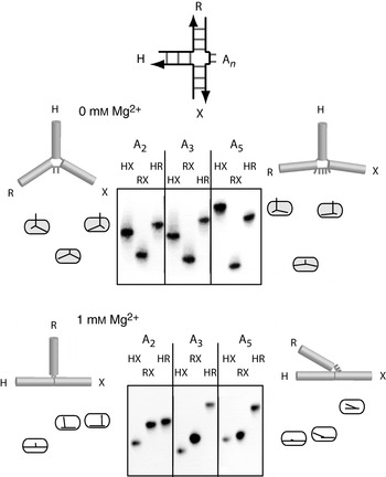
Leontis et al. (Reference Leontis, Kwok and Newman1991) first showed that such bulged three-way junctions had increased stability, based on gel electrophoresis studies. Using comparative gel electrophoresis, we then observed (Welch et al. Reference Welch, Duckett and Lilley1993) that 3HSn junctions undergo an ion-induced conformational change (Fig. 11). In the absence of added ions, the junctions were unstacked and extended, but they underwent a folding transition upon addition of Mg2+ or other multivalent ions. These results were interpreted in terms of the formation of a structure in which two arms became coaxially stacked, whereas the third subtended an angle that was dependent upon the number of unpaired bases. Evidently the addition of the single-stranded section increased the flexibility of the junction so that the thermodynamic advantage of helical stacking was not exceeded by steric strain. This structure is consistent with steady-state (Stühmeier et al. Reference Stühmeier, Welch, Murchie, Lilley and Clegg1997) and time-resolved (Yang & Millar, Reference Yang and Millar1996) FRET studies, in which the end-to-end distance between two helices was reduced as the number of unpaired bases increased. Conclusions from the electrophoresis were also consistent with lowered rates of cyclisation of DNA containing a bulged junction, compared with those carrying a perfectly paired junction (Shlyakhtenko et al. Reference Shlyakhtenko, Appella, Harrington, Kutyavin and Lyubchenko1994).
Electrophoretic analysis of three-way DNA junctions containing additional unpaired nucleotides (Welch et al. Reference Welch, Duckett and Lilley1993). The extra nucleotides are n=2, 3 or 5 adenines, indicated by A n in the schematic, where the three helical arms are named H, R and X. Comparative gel electrophoresis in 8% polyacrylamide gels compares the mobility of the three species derived by shortening one arm, to leave two long arms. (a) In the absence of added metal ions [90 mm Tris–borate (pH 8·3) and 10 mm EDTA], the mobility patterns are slow–fast–slow, where the separation between fast and slow species increases with the number of unpaired adenine nucleotides. This is consistent with an extended structure, where the R–bulge–X angle increases with n. (b) Addition of Mg2+ ions [90 mm Tris–borate (pH 8·3) and 1 mm Mg2+] markedly changes the electrophoretic pattern. The three patterns are variations on fast–intermediate–slow, strongly influenced by n once again. They can be interpreted in terms of a structure based upon coaxial stacking of arms H and X, but where the angle subtended by the third helix R depends on the number of unpaired adenine nucleotides as shown.

A 3HSn junction can in principle adopt one of three inequivalent conformations involving coaxial stacking of arms, since this can involve only two of the three arms (Fig. 12). One conformer is seldom found, as this places the unpaired nucleotides onto the continuous strand probably disrupting coaxial stacking. The remaining two forms are not stereochemically equivalent (unlike the two conformers of the four-way junction) and therefore unlikely to be equally stable. In one structure, the polarity of the bulge sequence is 3′ to 5′ as it leaves the stacked helices (conformer I), while in the other it is 5′ to 3′ (conformer II).
Alternative conformers of three-way DNA junctions analysed by comparative gel electrophoresis. Two 3HS2 junctions have been analysed (Welch et al. Reference Welch, Walter and Lilley1995), with their central sequences shown above the gels. (a) Electrophoresis in an 8% polyacrylamide gel of the three long–short species in the presence of Mg2+ ions [90 mm Tris–borate (pH 8·3) and 1 mm Mg2+] gives strikingly different patterns for the two sequences. These are interpreted in terms of either X on H stacking or R on H stacking as depicted. The polarity of the strands is indicated by the arrows; note that these two structures are not equivalent. (b) The structure of a junction with the central sequence shown on the right in (a) solved by NMR (Rosen & Patel, Reference Rosen and Patel1993a, Reference Rosen and Patelb). Unfortunately, the coordinates of this structure are no longer available, and this parallel-eye stereoscopic view is taken from the original publication with permission.

The majority of the sequences that we chose to study by comparative gel electrophoresis folded into the conformer I structure in the presence of metal ions (Welch et al. Reference Welch, Duckett and Lilley1993, Reference Welch, Walter and Lilley1995) (Fig. 12a). The stacked structure that emerged was in broad agreement with NMR studies of different sequences (Leontis et al. Reference Leontis, Hills, Piotto, Malhotra, Nussbaum and Gorenstein1993; Ouporov & Leontis, Reference Ouporov and Leontis1995; Overmars et al. Reference Overmars, Pikkemaat, van den Elst, van Boom and Altona1996; Thiviyanathan et al. Reference Thiviyanathan, Luxon, Leontis, Illangasekare, Donne and Gorenstein1999). Interestingly, however, in studies of unrelated 3HSn junctions, Rosen & Patel (Reference Rosen and Patel1993a, Reference Rosen and Patelb) found conformer II structures (Fig. 12b). We then carried out the electrophoretic analysis on a junction having the same central sequence as that of Rosen and Patel and found that this adopted the stacking conformer II (Welch et al. Reference Welch, Walter and Lilley1995), in complete agreement with the NMR analysis.
5. RNA junctions
Helical junctions are common elements in the secondary structure of RNA. They have a key role in the folding of small functional RNA molecules such as some of the nucleolytic ribozymes and are important in larger RNA species, organising the tertiary structure of the molecule. Comparative gel electrophoresis has been used to establish some general folding principles for RNA junctions and determine the global folds of a number of functionally important examples.
Applying the long–short arm method to RNA can be done in several ways depending on how the species are prepared. The component RNA chains may be generated by in vitro transcription, in which case, the shorter helices may be replaced with short stem-loops; indeed, there is no reason why the individual species cannot be made as a single polynucleotide. The only real drawback to this approach is that non-natural nucleotides cannot be introduced, and for this, chemical synthesis is required. However, RNA synthesis remains less routine than DNA, limiting the length of oligonucleotides that can be made. We have therefore generally adopted the approach of synthesising hybrid DNA–RNA–DNA molecules, so that the functionally significant core of the molecule is made of RNA, but the long arms are made from DNA after around a turn of helix. Hybrid species of 80 nt are relatively easy to synthesise, generating long arms of around 40 bp that result in good discrimination between the different angles of junctions. The RNA–DNA junctions that are created in the long arms do not detectably affect the results.
5.1 The simple 4H RNA junction
Perfectly paired (4H) junctions exist in a number of significant RNA species such as the hairpin ribozyme and U1 snRNA. Comparative gel electrophoresis revealed that these junctions exhibited a number of differences from their DNA equivalents (Duckett et al. Reference Duckett, Murchie and Lilley1995). Perhaps the most striking observation is that in the absence of added metal ions, coaxial helical stacking is not lost. Instead, the results were consistent with the formation of a stacked but parallel geometry. Upon addition of moderate concentrations of divalent metal ions, the electrophoretic pattern changed to one that could be interpreted in terms of a stacked structure with perpendicular axes. However, more recent single-molecule FRET studies have shown that this results from a rapid equilibrium between parallel and anti-parallel conformations (Hohng et al. Reference Hohng, Wilson, Tan, Clegg, Lilley and Ha2004). Increasing the concentration of metal ions generated electrophoretic patterns indicative of an anti-parallel structure. The change in the position of the equilibrium between parallel and anti-parallel forms with metal ion concentration can be followed by FRET, giving results indicative of folding induced by the non-cooperative binding of ions (Walter et al. Reference Walter, Murchie, Duckett and Lilley1998a).
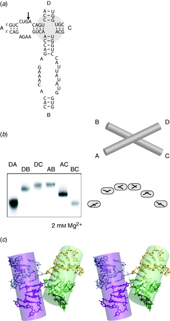
Probably the most extensively studied 4H junction in RNA is that of the hairpin ribozyme, both in situ (Murchie et al. Reference Murchie, Thomson, Walter and Lilley1998; Walter et al. Reference Walter, Murchie, Thomson and Lilley1998c) and as an isolated junction (Walter et al. Reference Walter, Murchie and Lilley1998b). The junction comprises helices A–D sequentially around, with functionally important unpaired loops present within helices A and B (Fig. 13a). Comparative gel electrophoresis revealed that the junction adopted an anti-parallel stacked X structure in the presence of divalent metal ions (Fig. 13b), with a biased stacking of A on D and B on C arms. Consequently, this form would juxtapose the two unpaired loops of the ribozyme within helices A and B ready for interaction. These conclusions were confirmed upon the solution of the X-ray crystal structure (Rupert & Ferré-D'Amaré, Reference Rupert and Ferré-D'Amaré2001) (Fig. 13c). Single-molecule FRET studies later emphasised the dynamic character of the hairpin junction, with transitions between anti-parallel and parallel forms and between alternative stacking conformers (Hohng et al. Reference Hohng, Wilson, Tan, Clegg, Lilley and Ha2004). They showed that the folding of the ribozyme into its active form in which there is an intimate interaction between the two loops is greatly accelerated by the presence of the four-way junction (Tan et al. Reference Tan, Wilson, Nahas, Clegg, Lilley and Ha2003).
Analysis of the 4H four-way RNA junction of the hairpin ribozyme by comparative gel electrophoresis. (a) The sequence of the complete ribozyme. The structure of the ribozyme is organised by a four-way junction. Arms A and B contain internal loops that interact to create the active form of the ribozyme; the cleavage site is marked with an arrow. (b) Electrophoretic analysis of the four-way junction in an 8% polyacrylamide gel, folded in the presence of Mg2+ ions [90 mm Tris–borate (pH 8·3), 2 mm Mg2+]. The junction was studied as a perfect 4H junction, with the loops of the A and B arms removed by complementation. The arms were extended with DNA, and the six long–short arm species were generated. The pattern of mobilities is interpreted in terms of the anti-parallel X-shaped structure shown, based on coaxial stacking of A on D and B on C arms. In the complete ribozyme, rotation of the junction allows intimate association between the loops. (c) Parallel-eye stereoscopic view of the structure of the four-way junction as it exists in the crystal structure of the complete hairpin ribozyme (Rupert & Ferré-D'Amaré, Reference Rupert and Ferré-D'Amaré2001). The four helical arms have been differentiated by colour. The image was generated from the coordinate file 1m5k.pdb.

The chirality of the isolated junction of the hairpin ribozyme was deduced to be opposite to that of the same junction contained within the complete ribozyme using an electrophoretic experiments involving a series of duplex containing the junction and a nucleotide bulge (Goody et al. Reference Goody, Lilley and Norman2004) discussed earlier.
5.2 Four-way RNA junctions containing formally unpaired nucleotides
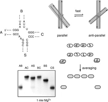
While most junctions found in RNA include one or more formally unpaired nucleotides, there have been few non-perfect four-way junctions studied. It would be expected that the structural and dynamic properties would be altered by the presence of the additional nucleotides, and this has been shown to be the case for the 2HS22HS1 four-way junction found in the hepatitis C virus IRES element (Fig. 14). We have studied the properties of this junction using comparative electrophoresis, together with FRET analysis (Melcher et al. Reference Melcher, Wilson and Lilley2003). In contrast to the 4H RNA junctions, the IRES junction was found to lose coaxial stacking and adopt an extended structure in the absence of added metal ions. On addition of divalent metal ions, the junction folded by pairwise coaxial stacking of arms, placing the extra nucleotides onto the exchanging strands. The pattern of electrophoretic mobilities of the six long–short arm species was consistent with a 90° cross of axes. However, time-resolved FRET studies suggested a more dynamic interpretation of the pattern, with a rapid exchange between approximately equal populations of parallel and anti-parallel conformations. Provided that the exchange is fast on the timescale of the gel electrophoresis, this should generate an average of the mobility patterns of the two forms that is completely consistent with the pattern obtained. This shows us that we must be alive to more complex interpretations of electrophoretic results in some situations. An earlier crystal structure of the IRES junction had shown that it crystallised in a parallel conformation (Kieft et al. Reference Kieft, Zhou, Grech, Jubin and Doudna2002), evidently freezing out this component of the dynamic equilibrium.
Analysis of the 2HS2 2HS1 four-way junction of the HCV IRES by comparative gel electrophoresis. The sequence of the junction around the point of strand exchange is shown. Comparative gel electrophoresis in a 10% polyacrylamide gel was performed in the presence of Mg2+ ions [90 mm Tris–borate (pH 8·3) and 1 mm Mg2+], using the six long–short arm species, where arms were extended with DNA sections. The observed pattern of mobilities is interpreted in terms of a rapid exchange between approximately equal populations of parallel and anti-parallel conformations as shown, with strand polarities indicated for clarity.

5.3 Three-way junctions in RNA
5.3.1 Three-way junctions are very common in RNA
Three-way junctions are probably by far the most common branchpoints found in natural RNA molecules. They are seldom found as simple 3H junctions but occur with varying degrees of complexity. Clearly, the presence of additional nucleotides between the helical sections increases conformational flexibility. Three-way junctions in crystallographic structures have been analysed by Lescoute & Westhof (Reference Lescoute and Westhof2006) and classified into three families whose structural characteristics depend on the relative length and positions of the connecting single-stranded sections. However, the overriding feature that emerges is that all junctions fold by the coaxial stacking of two of the three arms, much as discussed for three-way DNA junctions earlier.
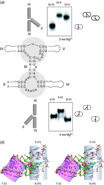
5.3.2 The VS ribozyme
The secondary structure of the trans-acting VS ribozyme (Beattie et al. Reference Beattie, Olive and Collins1995) (Fig. 15) creates two three-way junctions that organise the five helices (numbered II–VI) into an H shape. The top junction (in the conventional depiction of the ribozyme sequence) is an HS1HS5HS2 junction, while the lower junction is a 2HS5HS2 junction. Both exhibit two-state folding induced by the non-cooperative binding of divalent metal ions, and their structures have been analysed as free junctions by comparative gel electrophoresis (Fig. 15a). It was concluded that the upper junction folded by the coaxial stacking of arms IV and III, with an acute angle between helices V and III (Lafontaine et al. Reference Lafontaine, Norman and Lilley2002). The lower junction folded by the coaxial stacking of arms III and VI, with an acute angle between helices II and VI (Lafontaine et al. Reference Lafontaine, Norman and Lilley2001). These global structures were in full agreement with FRET measurements on the isolated junctions. Since the two junctions are joined through their common helix III, this naturally led to a model of the complete ribozyme (Lafontaine et al. Reference Lafontaine, Norman and Lilley2002). We analysed the dihedral angle subtended between helices II and V extending from the core of coaxially stacked helices IV–III–VI by using an experiment analogous to those in Section 3.5 (Lafontaine et al. Reference Lafontaine, Norman and Lilley2002). The modulation was relatively light, perhaps indicating that arms II and V are quite flexible or that the inter-helical angles are small.
Analysis of the two three-way RNA junctions of the VS ribozyme by comparative gel electrophoresis. (a) The structure of the VS ribozyme is shown, with the sequences of the two component three-way junctions indicated. Each was analysed in isolation by comparative gel electrophoresis in a 10% polyacrylamide gel in the presence of 90 mm Tris–borate (pH 8·3) using three long–short arms species generated by DNA extension of the arms. Both junctions undergo metal ion-dependent folding; the data are shown for the junctions folded in the presence of Mg2+ ions. The structural interpretations of both sets of data are shown. (b) Parallel-eye stereoscopic view of the structure of a closely similar three-way junction to the lower VS junction found in the ribosome. This sequence can be substituted into the VS ribozyme with retention of significant activity (Lafontaine et al. Reference Lafontaine, Norman and Lilley2001), suggesting that they have similar conformations. The global structure is closely similar to that deduced for the ribozyme junction II–III–VI, and the helices have been labelled with the names of the helices in the ribosomal RNA, with the VS ribozyme equivalents given in parenthesis. The structure is taken from the crystal structure of the 50S ribosomal subunit (Ban et al. Reference Ban, Nissen, Hansen, Moore and Steitz2000), using the coordinate file 1FFZ.pdb.

There are junctions of similar sequences to the two VS junctions found in the 23S rRNA. Inspection of their structures within the crystal structure of the 50S ribosomal subunit shows that they adopt global structures equivalent to those deduced from electrophoresis. For example, the 5–6–7 junction of the 23S rRNA has a very similar sequence to that of the II–III–VI junction of the VS ribozyme, and when this was transplanted into the VS sequence, the ribozyme retained its catalytic activity (Lafontaine et al. Reference Lafontaine, Norman and Lilley2001). The global structure of this junction in the crystal structure of the ribozyme (Ban et al. Reference Ban, Nissen, Hansen, Moore and Steitz2000), shown in Fig. 15b, is the same as that deduced for the ribozyme junction by comparative gel electrophoresis and FRET. Despite the best efforts of a number of laboratories, there is no crystal structure for the VS ribozyme yet available. However, we have recently carried out an analysis of the complete ribozyme (including the substrate helix and another that makes an additional three-way junction) and its component junctions using small-angle X-ray scattering (SAXS) in solution (Lipfert et al. Reference Lipfert, Ouellet, Norman, Doniach and Lilley2008). The results are in good agreement with the earlier model based on the ‘divide and conquer’ approach of building up from the structures of the isolated junctions.
5.3.3 The hammerhead ribozyme
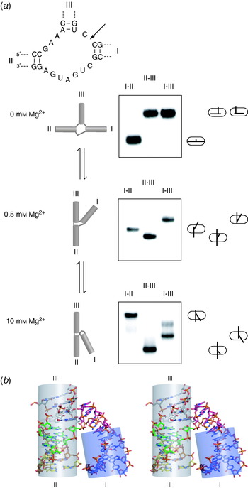
The catalytic core of the hammerhead ribozyme is an HS1HS7HS3 junction, with three helices named I, II and III (Fig. 16). This was first analysed by electrophoresis at much the same time as its structure was solved by X-ray crystallography. Using comparative gel electrophoresis (Bassi et al. Reference Bassi, Møllegaard, Murchie, von Kitzing and Lilley1995), we found that in the presence of divalent metal ions, the hammerhead junction folded by the coaxial stacking of helices III on II, with an acute angle subtended between helices I and II, and this was in complete agreement with the structures observed in the crystal (Pley et al. Reference Pley, Flaherty and McKay1994; Scott et al. Reference Scott, Finch and Klug1995). However, the folding of the hammerhead junction was rather more complex than had been found for simpler junctions such as those of the VS ribozyme. Analysis of the electrophoretic mobility patterns as a function of Mg2+ ion concentration indicated that it folded in two steps (Fig. 16a), with a distinct species existing at intermediate Mg2+ concentration in which helices II and III were coaxially stacked, but helix I was directed into the same quadrant as helix III (Bassi et al. Reference Bassi, Møllegaard, Murchie, von Kitzing and Lilley1995). This scheme was confirmed by FRET studies (Bassi et al. Reference Bassi, Murchie, Walter, Clegg and Lilley1997) and could be rationalised in terms of the crystal structures (Pley et al. Reference Pley, Flaherty and McKay1994; Scott et al. Reference Scott, Finch and Klug1995), which showed the formation of two distinct domains within the structure. The electrophoretic and FRET results of the natural hammerhead sequence, together with those of sequence substitutions that blocked folding at different stages (Bassi et al. Reference Bassi, Murchie and Lilley1996, Reference Bassi, Møllegaard, Murchie and Lilley1999), were consistent with the sequential formation of these two domains as the metal ion concentration increased. The global structure of the ribozyme fully folded in the presence of 10 mm Mg2+ ions was in excellent agreement with that found in the crystal structures of the ribozyme (Pley et al. Reference Pley, Flaherty and McKay1994; Scott et al. Reference Scott, Finch and Klug1995); an example is shown in Fig. 16b.
Analysis of the folding of the three-way RNA junction of the hammerhead ribozyme as a function of Mg2+ ion concentration by comparative gel electrophoresis. The sequence of the ribozyme core is shown, with the position of ribozyme cleavage marked with an arrow. (a) The electrophoretic analysis is shown for three different Mg2+ ion concentrations in 8% polyacrylamide gels in the presence of 90 mm Tris–borate (pH 8·3). Comparative gel electrophoresis was performed by generating three long–short arms species by DNA extension of the arms. In the absence of Mg2+ ions the junction is extended, with a large angle subtended between helices I and II. The mobility patterns in the presence of added metal ions are interpreted in terms of coaxial stacking of helices II and III (the species with shortened helix I is consistently the fastest), but the angle subtended by helix I depends on the Mg2+ ion concentration as shown. The final shape of the ribozyme in the presence of 10 mm Mg2+ is in good agreement with the structure found in the crystal by X-ray diffraction. (b) Parallel-eye stereoscopic view of the structure of the hammerhead ribozyme as found in a crystal structure. This is the minimal form of the ribozyme (Feig et al. Reference Feig, Scott and Uhlenbeck1998), lacking the interacting loops that form a tertiary interaction that leads to an alteration of the core structure (Khvorova et al. Reference Khvorova, Lescoute, Westhof and Jayasena2003). The image was generated from the coordinate file 359d.pdb.

More recently, it has been found that tertiary contacts between elements within helices I and II that were missing in all the original constructs are important in the function of the ribozyme in physiological conditions (Khvorova et al. Reference Khvorova, Lescoute, Westhof and Jayasena2003; Canny et al. Reference Canny, Jucker, Kellogg, Khvorova, Jayasena and Pardi2004) and induce a different structure in the core (Martick & Scott, Reference Martick and Scott2006). We found that inclusion of these elements led to folding in a single step at significantly lower Mg2+ concentrations (Penedo et al. Reference Penedo, Wilson, Jayasena, Khvorova and Lilley2004).
6. DNA–protein complexes
6.1 Proteins that bind to DNA junctions
There are many proteins that bind to DNA junctions, most of which exhibit marked selectivity for the structure of the branched DNA (Lilley & White, Reference Lilley and White2001). The majority of the well-studied proteins are junction-resolving enzymes; these are dimeric nucleases that target four-way DNA junctions and cleave two strands to resolve them into nicked duplex species. Another class of proteins are those involved in branch migration of four-way junctions. In general, junction-selective proteins are not displaced by a large excess of duplex DNA.
The question arises as to whether these proteins bind to four-way junctions in the stacked X structure or whether the binding induces a distortion of the DNA structure: can we apply the method of comparative gel electrophoresis to the DNA–protein complexes? The protein is bound to the usual set of species with two long arms in the different combinations and electrophoresed side by side as before. In general, the complexes are significantly retarded in the gel, so that there is a good separation between free DNA and the complexes. The different long–short arm species of the complexes may then be compared and the pattern of mobilities analysed. The method works well and has provided a good test of the general applicability of the method. It has given excellent descriptions of the global shape of complexes, to be confirmed much later by crystallographic study. It has proved possible to disentangle systems containing alternative conformations in slow exchange. Altogether, the method has been well up to the challenge of analysing junction–protein complexes.
6.2 The Escherichia coli RuvA protein
The RuvA protein acts in conjunction with RuvB to promote branch migration of Holliday junctions in E. coli. It binds the junction as a flat tetramer, with one face that is strongly electropositive (Rafferty et al. Reference Rafferty, Sedelnikova, Hargreaves, Artymiuk, Baker, Sharples, Mahdi, Lloyd and Rice1996). Comparative gel electrophoresis was applied to the complex of a junction with a RuvA tetramer by West and co-workers (Parsons et al. Reference Parsons, Stasiak, Bennett and West1995). They found the classical open-square pattern of mobilities, i.e. slow–fast–slow–slow–fast–slow. This indicated that the binding of the RuvA protein induces an almost total unfolding of the junction into a structure that resembles that of the free junction in the absence of metal ions. A structure of a four-way DNA junction bound by two tetramers of RuvA was solved by X-ray crystallography, with the predicted open-square conformation of the junction (Roe et al. Reference Roe, Barlow, Brown, Oram, Keeley, Tsaneva and Pearl1998).
6.3 The junction-resolving enzymes Cce1, Ydc2 and RuvC
RuvC of E. coli and Cce1 of the yeast Saccharomyces cerevisiae are junction-resolving enzymes that are both members of the integrase superfamily (Lilley & White, Reference Lilley and White2000; Makarova et al. Reference Makarova, Aravind and Koonin2000). The global shape of a DNA junction bound to Cce1 was analysed by comparative gel electrophoresis (Fig. 17). The six long–short arm species of the complex migrated with a simple slow–fast–slow–slow–fast–slow pattern (White & Lilley, Reference White and Lilley1997), again indicative of an open-square geometry. The fraction of protein-free junction migrating lower down the gel gives the pattern expected for the stacked X structure. The opening of the centre of the junction by Cce1 was supported by the chemical reactivity of thymine bases located at the point of strand exchange and by the enhanced fluorescence of 2-aminopurine bases incorporated into the junction centre (Déclais & Lilley, Reference Déclais and Lilley2000); indeed, these results indicate that the central base pairs are probably broken as well as unstacked. Closely similar results have been obtained using comparative gel electrophoresis on the complex of a four-way junction with the related resolving enzyme Ydc2 from the fission yeast S. pombe (White & Lilley, Reference White and Lilley1998). Rafferty and co-workers (McGregor et al. Reference McGregor, Ayora, Sedelnikova, Carrasco, Alonso, Thaw and Rafferty2005) have also applied the comparative gel electrophoresis method to a complex of a DNA junction bound by RecU, finding that this too adopts the open-square conformation.
Analysis of the global shape of a four-way DNA junction bound to the resolving enzyme Cce1 using comparative gel electrophoresis. The six long–short helix species of junction 1 (i.e. the same junction that is analysed in Fig. 8) were incubated with a sub-saturating concentration of Cce1 and electrophoresed in a 6% polyacrylamide gel in the presence of 90 mm Tris–borate (pH 8·3) and 200 μm Mg2+ ions. The Cce1-bound complexes are significantly retarded with respect to the protein-free junction. The free junction species migrate to give a fast–intermediate–slow–slow–intermediate–fast pattern of the stacked X structure in the isoI conformer. However, the complexes have a very different pattern of mobility, showing that Cce1 binds to the junction in the open-square form, indicated on the right side.

The conformation of a DNA junction bound to RuvC was analysed by Bennett & West (Reference Bennett and West1995). The pattern of electrophoretic mobilities was a little different from the open square but could be readily interpreted in terms of a similar structure in which the junction has an opened centre and a twofold symmetrical X shape. The global geometry of this complex has also been analysed by FRET, using fluorophores terminally attached to different pairs of helical arms (Fogg et al. Reference Fogg, Kvaratskhelia, White and Lilley2001); the results were fully consistent with the structure deduced from comparative gel electrophoresis. Unfortunately, no crystal structure has been obtained to date of a complex of Cce1, Ydc2 or RuvC with a DNA junction, so the ultimate test of these structures still awaits.
6.4 T4 endonuclease VII
Endonuclease VII of phage T4 proved to be a somewhat more difficult problem to analyse. The pattern of electrophoretic mobilities of the six species of complex with one junction are shown in Fig. 18a (Pöhler et al. Reference Pöhler, Giraud-Panis and Lilley1996). At first sight, this rather unsymmetrical pattern has no obvious interpretation. However, we realised that it could be explained by first proposing a distortion into an open, planar X structure like that of the RuvC complex, and then imposing a small further distortion by taking two diametrically opposite helices out of the plane. What made this more convincing was the finding that by changing the central sequence of the junction, the mobility pattern for the complexes was altered in a way that could be explained by formation of the same structure, but with the planar and out-of-plane helices exchanged.
Analysis of the global shape of a four-way DNA junction bound to the resolving enzyme T4 endonuclease VII complex using comparative gel electrophoresis. (a) The electrophoretic analysis. The six long–short helix species of junction 1 bound to endonuclease VII E86A (a mutant of lowered activity) were electrophoresed in an 8% polyacrylamide gel in the presence of 90 mm Tris–borate (pH 8·3) and 100 μm Mg2+ ions; only the complexes are contained within the section of the autoradiograph shown. The mobility pattern of the complexes can be described as intermediate–fast–slow–slow–intermediate–intermediate. This is different from any pattern previously observed and requires an explanation most easily shown in two stages, on the right side. Beginning from the open-square structure, the helices are moved to form a planar X shape, with acute angles between X and B and R and H; this would give the predicted pattern of mobilities shown. While this describes some of the features of the experimental pattern, it is too symmetrical. The symmetry may be lowered by directing helices X and H out of the plane, narrowing the angle between them and thus lowering the mobility of the HX species. This pattern provides a good description of the experimental mobilities. (b) Parallel-eye stereoscopic view of the crystal structure of a complex between endonuclease VII and a four-way junction by Yang and co-workers (Biertümpfel et al. Reference Biertümpfel, Yang and Suck2007). The two polypeptides are shown space-filling (in green). The view shown is down onto the face of the complex, from the DNA side. The disposition of the four helical arms of the junction in the complex is exactly that deduced from the electrophoresis; the junction adopts an X shape, with two diametrically opposite helices directed 25° out of plane. The image was generated from the coordinate file 2qnc.pdb.

The global structure of the endonuclease VII–junction complex has been confirmed by the very recent co-crystal structure by Yang and co-workers (Biertümpfel et al. Reference Biertümpfel, Yang and Suck2007) (Fig. 18b). This beautiful structure shows the general X shape of the DNA junction and confirms the out-of-plane distortion of two helices, by 30°. These arms are pushed into this position by a ‘pedestal’ of three α helices.
6.5 T7 endonuclease I
Endonuclease I of phage T7 was an even greater challenge for comparative gel electrophoresis than was endonuclease VII. The electrophoretic mobility patterns were found to differ in the presence or absence of divalent metal ions, and the patterns in the presence of Ca2+ ions were quite complex. Figure 19a shows the electrophoretic separation of the six species of the complex of endonuclease I bound to a four-way DNA junction in the presence of 200 μm Ca2+ ions (Déclais et al. Reference Déclais, Fogg, Freeman, Coste, Hadden, Phillips and Lilley2003). The pattern is complicated, with a number of the species migrating as two separate bands. Yet this could be deconvoluted into the sum of two patterns, each of which was interpreted in terms of a DNA structure where the helical arms remain coaxial, with an angle that is almost, but not quite, perpendicular. The separated patterns correspond to the two possible alternative structures for the complex, differing in the coaxial pairing of helices (i.e. B coaxial with X or with H). Thus it was concluded that there were two alternative conformers of the complex present in solution, and the intensities of the electrophoretic bands suggested a 4:1 bias in favour of one of these; this was consistent with the ratio of cleavage of the different strands of the junction by active endonuclease I (Déclais et al. Reference Déclais, Fogg, Freeman, Coste, Hadden, Phillips and Lilley2003). The two conformers are in very slow exchange, since they migrate as well-resolved individual species. Remarkably, the patterns could be resolved into single conformers if a central phosphate (or both phosphates) was electrically neutralised by replacement with methyl phosphonate (Déclais et al. Reference Déclais, Liu, Freeman and Lilley2006). The conclusion of coaxial alignment of helices left something of a dilemma. We knew this could not be simple coaxial stacking of helices because the central nucleotides were clearly disrupted (Déclais et al. Reference Déclais, Fogg, Freeman, Coste, Hadden, Phillips and Lilley2003), yet the electrophoretic data strongly suggested coaxial alignment. While it is tempting to conclude that if helices are coaxial they are probably continuously stacked, this appeared not to be the case for the endonuclease I complex.
Analysis of the global shape of a four-way DNA junction bound to the resolving enzyme T7 endonuclease I complex using comparative gel electrophoresis. (a) The electrophoretic analysis. The six long–short helix species of junction 3 bound to endonuclease I were electrophoresed in a polyacrylamide gel in the presence of 90 mm Tris–borate (pH 8·3) and 200 μm Ca2+ ions (the enzyme is inactive in the presence of Ca2+ ions). Only the complexes are contained within the section of the phosphorimage shown. The mobility pattern of the complexes is complicated by the presence of double bands for four of the species, indicating the presence of two different complexes in slow exchange. These are interpreted in terms of two alternative forms (akin to the stacking conformers of the free junctions) for the bound complexes, differing only in which helices are coaxial. The structure of each form of the complex can be described as an almost (but not exactly) perpendicular cross of coaxially aligned helical arms, with the interpretation shown. Note that species BR and HX for the alternative complexes co-migrate according to this model. (b) Parallel-eye stereoscopic view of the crystal structure of a complex between endonuclease I and a four-way junction (Hadden et al. Reference Hadden, Déclais, Carr, Lilley and Phillips2007). A form of the junction that was biased to adopt a single conformer was used for the crystallisation. The two polypeptides are shown space-filling (in green). The disposition of the four helical arms of the junction in the complex is in good agreement with that deduced from the electrophoresis, with an angle of 80° subtended between the helical axes. The image was generated from the coordinate file 2pfj.pdb.

The geometry of the complex of endonuclease I and the DNA junction has been confirmed in all respects by a new co-crystal structure of the complex (Hadden et al. Reference Hadden, Déclais, Carr, Lilley and Phillips2007) (Fig. 19b). This shows that the helices are indeed aligned in coaxial pairs, with an inter-axial angle of 80°. Despite the coaxial alignment of the helices, significant central disruption was observed at the centre of the junction, with a 10-Å gap between junction–proximal base pairs of coaxial helices. Once again, the comparative gel electrophoresis and crystallography were in full agreement.
Conclusion
Comparative gel electrophoresis has consistently provided structural solutions to the analysis of conformation in branched nucleic acids. It can provide information on DNA and RNA species and their complexes with proteins. Used carefully, the conformation of multiple species in slow equilibria can be extracted from the electrophoretic data, and in some cases, it has provided an early indication of fast dynamic processes. The biggest limitation of the approach is probably the lack of a good theoretical basis for the technique and consequently the largely qualitative descriptions that result. However, these can provide key insights into the folding of important species. Moreover, comparative gel electrophoresis is best used in conjunction with other methods that provide complementary information. The longest-standing example of that is probably the combination with distance information from FRET, but electron paramagnetic resonance and SAXS are also valuable adjuncts. In some cases, comparative gel electrophoresis has allowed us to choose between alternative families of structures resulting from the application of FRET distances in modelling the structures of junctions.
Comparative gel electrophoresis has proved to be a robust method for the analysis of branched nucleic acid structure, with notable successes. Just as importantly, in our hands, there has been no case in which it has been subsequently proved incorrect. It can thus be applied to new structural problems with confidence.
Acknowledgements
The author thanks the many co-workers who have contributed to the studies discussed in this review, including Derek Duckett, Alastair Murchie, Anamitra Bhattacharrya, Terry Goody, Jonathan Welch, Richard Grainger, Sonya Melcher, Richard Pöhler, Malcolm White, Anne-Cécile Déclais, Jia Liu, Gurminder Bassi and Daniel Lafontaine.