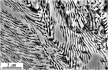
I. INTRODUCTION
High-entropy alloys (HEAs), which lead us to a new stage in the study of material science, have been generated significant interest from the scientific community.Reference Yeh, Chen, Lin, Gan, Chin, Shun, Tsau and Chang1,Reference Cantor, Chang, Knight and Vincent2 The published literature studies reported that many HEA systems exhibit chemical, physical, mechanical, functional, and other exceptional properties, such as high-temperature oxidation-resistant,Reference Huang, Zhang, Shen and Vilar3 elevated-temperature strength, good wear resistance,Reference Tong, Chen, Yeh, Lin, Chen, Shun and Chang4 low density,Reference Senkov, Senkova, Woodward and Miracle5,Reference Youssef, Zaddach, Niu, Irving and Koch6 high phase stability against irradiation,Reference Nagase, Rack, Noh and Egami7 cryogenic stability, low-temperature fracture resistance,Reference Qiao, Ma, Huang, Chuang, Liaw and Zhang8,Reference Gludovatz, Hohenwarter, Catoor, Chang, George and Ritchie9 formation of nanostructures,Reference Zhang, Pan, He and Jiao10,Reference Wen, Kou, Li, Chang, Xue and Zhou11 high yield and fracture strength,Reference Xia, Yang, Chen, Yang and Zhang12 special near-zero thermal coefficient of electrical resistivity,Reference Chen and Kao13 and so on. These splendid characters prompt the research studies on utilizing HEAs in our daily life. Yet, a certain gap between research and actual industrial process still exists. As it is known that the HEAs can hold either high strength or high ductility. However, the simultaneous achievement of both high strength and ductility still confronts a tough challenge. Moreover, the inferior castability and compositional segregation of HEAs has also been another obstacle for their practical applications. From the traditional metallurgical theory, the eutectic alloys are known to be a good candidate to sweep out these issues because the eutectic solidification structure has the following features: (i) near-equilibrium microstructures, which can keep more stable at the high temperature; (ii) low-energy in phase boundaries; (iii) controllable microstructures; (iv) high rupture strength; (v) stable defect structures; (vi) good high-temperature creep resistance; (vii) regular lamella or rod-like eutectic organization, which can form an in situ composite.Reference Glicksman14 Also importantly, isothermal transformation in the eutectic reaction can lower the solidification temperature range and segregation as well as the shrinkage cavity. Hence, combining FCC and other hard phase structures can possess both the advantages of mechanical properties and excellent castability of eutectic alloys. Therefore, a novel concept called “eutectic high-entropy alloys” (EHEAs) was recently proposed by Lu et al.,Reference Lu, Dong, Guo, Jiang, Kang, Wang, Wen, Wang, Jie, Cao, Ruan and Li15 and related papers come out one after another. Their solidification process, microstructure,Reference Mishra, Samal and Biswas16–Reference Tan, Li, Wang and Kou19 mechanical properties,Reference He, Wang, Shang, Leng, Li and Wang20–Reference Lu, Gao, Jiang, Chen, Wang, Jie, Kang, Zhang, Guo, Ruan, Zhao, Cao and Li23 compositional designing concept, and related calculationReference He, Wang, Cheng, Wang, Li, Dang, Wang and Liu24–Reference Ding, He and Yang26 as well as the annealing treatment were reported.Reference Dong, Jiang, Jiang, Lu, Wang and Li27
Enlightened by these achievements and using the eutectic alloy concept, in this paper, a CoCrFeNiMox HEA system was designed to obtain the eutectic structure. Previous reports have shown that Mo elements tend to form compound phase, such as CoFeNiVMoy alloys, due to the larger atomic size difference and mixed enthalpy between Mo and other elements. Moreover, CoCrFeNi as a matrix tends to form a relatively stable soft FCC structure. Given all that, in this study, CoCrFeNiMox HEAs were synthesized and prepared. Their as-cast microstructures, phases, and mechanical properties were characterized and investigated.
II. MATERIALS AND METHODS
The CoCrFeNiMox alloys (x is the atomic content of Mo element when the atomic content of Co, Cr, Fe, and Ni are 1, 1, 1, and 1. In this paper, x = 0.2, 0.4, 0.6, 0.8, 1.0, and 1.2 denoted as Mo0.2, Mo0.4, Mo0.6, Mo0.8, Mo1.0, and Mo1.2, respectively) were prepared using commercially pure metal (purity higher than 99%) by the arc melting method under argon atmosphere protection. The ingots were repeatedly melted at least five times to assure chemical homogeneity and then directly solidified in a water-cooled copper mold. The solidified cylindrical rod ingots were about 6 mm in diameter and 70 mm in length. Five samples for each group of CoCrFeNiMox alloys were prepared for compression experiments to ensure the accuracy. The dimension (from ASTM E9-89a28) of the samples used in the compression test is about ϕ 6 mm × 12 mm.
The crystal structure, microstructure, and mechanical properties of these alloys were investigated. The specimens were polished then etched with aqua regia for observation under scanning electron microscopy (SEM; ZEISS Sigma500, Carl Zeiss, Oberkochen, Germany). Crystal structures were identified using an X-ray diffractometer (D/max-2500/PC, Rigaku, Tokyo, Japan) using Cu Kα radiation. Scanning angles ranged from 20 to 100° with the scanning rate of 5° per minute. The chemical composition analysis was carried out by SEM energy dispersive spectrometry (EDS; Oxford XMax-50, Oxford Instrument, Abingdon, United Kingdom). Room temperature Vickers hardness measurements were performed using HVS-1000CCD hardness testing machines (Shanghai Lianer Testing Equipment Co., Ltd., Shanghai, China). The compressive stress–strain curves were measured on a CMT 5305 Instron machine (SANS, Shenzhen, China) with a crosshead speed of 0.1 mm/min.
III. RESULTS AND DISCUSSION
A. Crystal structure and phase characterization
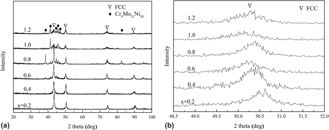
Figure 1(a) gives the XRD patterns of the as-cast CoCrFeNiMox ingots which have different Mo contents. The results show that Mo0.2 and Mo0.4 alloys possess a single FCC structure as Liu and Shun et al. reported.Reference Shun, Chang and Shiu29,Reference Liu, Lu, He, Luan, Wang, Liu, Liu, Chen and Liu30 Additional Mo atoms dissolve in the FCC solid solution with a lower x value. It will cause the solid solution strengthening simultaneously. With the increase of Mo content, when it surpasses the solid solubility limit, the negative mixing enthalpy of the Mo element with other elements will promote the intermetallic phase formation.Reference He, Wang, Cheng, Wang, Li, Dang, Wang and Liu24 As shown in Fig. 1(a), a new intermetallic compound Cr9Mo21Ni20 appears (orthorhombic system, Pbnm(62) space group, related to pdf card PDF#65-7733). Then the crystal structure transformed from the previous single FCC crystal structure to an FCC + Cr9Mo21Ni20 mixed structure with the increasing Mo content. The total intensity of the Cr9Mo21Ni20-type intermetallic phase is significantly increasing with elevating Mo content. Figure 1(b) shows the enlarged view of XRD patterns of FCC at 2θ = 48.5–52.0°. It is worth noting that the peak initially shifts to left as x lower than 0.8, while remains almost unchanged at x = 1.0 and 1.2. This would be because Mo atoms with the largest atomic radius can cause lattice distortion and thus increase the lattice constants when x < 0.8.Reference Jiang, Han, Qiao, Lu, Cao and Li31 While x > 0.8, the solid solubility reaches the limit. Thus, there is no change in lattice constants. In another perspective, the enormous formation of the Cr9Mo21Ni20-type phase will release the lattice distortion energy when the Mo element exceeds the solution limit, and severe lattice distortion can promote the formation of other microstructures, such as nanostructures, which also reduce the intensity of the diffraction peaks. The change in the crystal structure will have important effects on the microstructures and properties of the alloys, which will be discussed in detail in the following sections.
XRD patterns of the as-cast CoCrFeNiMox alloys: (a) All the XRD patterns when x = 0.2, x = 0.4, x = 0.6, x = 0.8, x = 1, and x = 1.2; (b) enlarged view of (a) at 2θ = 48.5–52.0°.

B. Microstructural evolution and elemental distribution
1. SEM observation
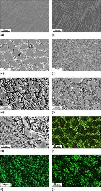
Microstructure evolution with different Mo ratios is presented in Fig. 2. When x = 0.2 and 0.4, the alloys show a typical dendritic structure, as shown in Figs. 2(a) and 2(b). Combining the XRD results, the dendrite is an FCC crystal structure (marked as α phase). When the Mo content increases to 0.6, the microstructure transforms into two obvious phases, which would be the hypoeutectic microstructure. One is bulk-like structure and another is eutectic-like structure, as shown in Fig. 2(c). It can be inferred from the theory of eutectic solidification and the results of XRD that the bulk is the α phase and the eutectic-like region is the eutectic structure (marked as E region) composed of α phase and Cr9Mo21Ni20-type intermetallic compound (marked as β phase). It can also be concluded that α phase is the proeutectic phase. A typical fully eutectic lamellar microstructure was obtained in Mo0.8, as presented in Fig. 2(d) and the corresponding magnified picture is Fig. 2(g). The superfine lamellar spacing of the Mo0.8 alloy was about only 110 nm, far thinner than other EHEAs reported previously.Reference Mishra, Samal and Biswas16,Reference Jiang, Cao, Jie, Zhang, Lu, Wang and Li18,Reference Lu, Gao, Jiang, Chen, Wang, Jie, Kang, Zhang, Guo, Ruan, Zhao, Cao and Li23,Reference Lu, Jiang, Guo, Wang, Cao and Li25 When the Mo content continuously increases (x > 0.8), the compound particles gradually grow simultaneously to turn a block shape and the microstructure change to a hypereutectic structure as shown in Figs. 2(e) and 2(f). Meanwhile, the β phase became the proeutectic phase. The eutectic structure shows up and continuously exists even x equals to 1.2. This change in the tissue morphology and grain size will lead to changes in the mechanical properties of the alloys.
SEM micrographs of the as-cast CoCrFeNiMox alloys with different Mo contents: (a) x = 0.2; (b) x = 0.4; (c) x = 0.6; (d) x = 0.8; (e) x = 1; (f) x = 1.2; (g) enlarged micrographs for x = 0.8; the EDS mappings of Mo [(h) x = 0.6; (i) x = 1; (j) x = 1.2].

2. Elemental distribution
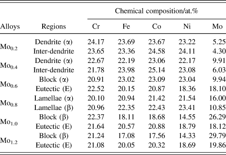
Table I summarizes the EDS results of different regions of the as-cast CoCrFeNiMox alloys. It is found that the elements approximately match the nominal composition as designed. The Mo0.2 and Mo0.4 alloys, which have only an FCC phase, exhibited relatively uniform elemental distribution, no matter in the dendrite or interdendrite regions. That is probably because the Fe, Co, and Ni elements are neighbors in the periodic table of elements, their atomic sizes are similar, and their mixing enthalpy is close to zero.Reference Jiang, Cao, Jie, Zhang, Lu, Wang and Li18,Reference Jiang, Lu, Dong, Wang, Cao and Li32 Therefore, these three elements tend to distribute uniformly in the alloys as predicted. The chemical analysis also shows that the α phase has relatively low Mo content. As for the Mo0.6–Mo1.2 alloys, the E region as well as the β phase are enriched with the Mo element. This demonstrates that the Mo element can promote the formation of the eutectic microstructure in the CoCrFeNiMox system. Combining with the XRD results, the phase formation procedure becomes clear and explicit.
Elemental analysis for every content of CoCrFeNiMox alloys.

Figures 2(h)–2(j) show the EDS mappings of the Mo element of Mo0.6, Mo1.0, and Mo1.2, corresponding to Figs. 2(c), 2(e), and 2(f), respectively. The brighter region denotes more Mo distribution. One can see that in Fig. 2(h), the dim region corresponds to the α phase, whereas the bright region corresponds to the eutectic structure. This indicates that the Mo element is mainly distributed in the eutectic structure in the hypoeutectic alloys when x < 0.8, which agree with the elemental distribution in Table I. On the contrary, in Figs. 2(i) and 2(j), the brighter region denotes the β phase, while the darker region is the eutectic structure. This is because β phase is the Cr9Mo21Ni20-type intermetallic compound with more Mo content, while the eutectic structure is composed of α and β phases, and of which the α phase has even less Mo content. To sum up, the EDS mappings are consistent with the SEM observations and conclusions we made before.
C. Mechanical properties and fracture appearance
1. Hardness
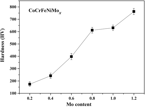
The Vickers hardness curve of the CoCrFeNiMox alloys is plotted in Fig. 3. It is found that the hardness increases from initially from 172.8 to 763.7 HV with the increase of Mo content. However, it increases slowly when x is under 0.4, and then it has an approximately linear increase from Mo0.4 to Mo0.8 alloys. Later, a large increment detected after a little boost when 0.8 ≤ x ≤ 1.2. Combining with the previous analysis, the hardness variation trend can be explained as follows. When the Mo content is lower than 0.4, the alloy hardness is only about 290 HV. This is because the larger radius of Mo atoms dissolves in the FCC lattice, resulting in a large lattice distortion and significant solid solution strengthening simultaneously.Reference Jiang, Cao, Jie, Zhang, Lu, Wang and Li18 Due to the good plasticity of the FCC structure, the microhardness possesses a minor increasing rate. Then, in the process of increasing Mo content, hard compounds appeared and combined with FCC to form the eutectic structure. The elevated eutectic volume enhances the hardness in almost linear way. There exists an inflection point when x = 0.8, of which the microstructure is a fully eutectic structure. The thinner lamellae space with Mo addition promotes a tiny hardness increase. After that, enormous β pulled hardness into a higher state. This trend is extremely assembling to CoFeNixVMo EHEAs as reported.Reference Jiang, Cao, Jie, Zhang, Lu, Wang and Li18
Hardness curve of the as-cast CoCrFeNiMox alloys with different Mo contents.

2. Compressive properties
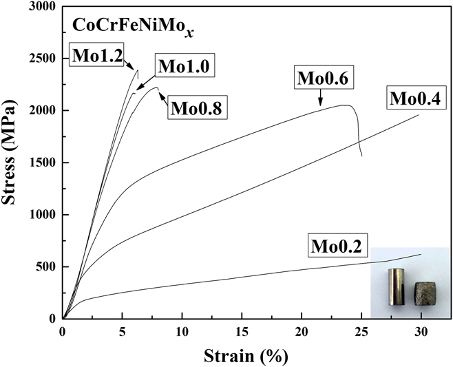
Figure 4 shows the room temperature compressive stress–strain curves of CoCrFeNiMox alloys. Evidently, the Mo content has a very pronounced effect on the compressive behavior of the CoCrFeNiMox alloys. Specially, the Mo0.2 and Mo0.4 specimens exhibit the upsetting phenomenon due to the whole volume of the soft FCC phase, as shown in the right bottom of Fig. 4. But for Mo0.6, Mo0.8, Mo1.0, and Mo1.2 alloys, the specimens were fractured during the test because of the hard Cr9Mo21Ni20-type intermetallic compounds. The hypoeutectic Mo0.6 specimens exhibit a combination of both high strength and high ductility, which are 2051 MPa and 23%, respectively. It is notable that Mo0.8, Mo1.0, and Mo1.2 have an unapparent yield phenomenon. Meanwhile, the compressive fracture stresses and compressibility are almost the same value, which are 2260 MPa, 2219 MPa, and 6.8%, respectively. The eutectic Mo0.8 and hypereutectic Mo1.0 and Mo1.2 alloys are composed of two phases, the intermetallic compound phase and the FCC phase. The hard, brittle Cr9Mo21Ni20-type intermetallic compounds downgrade the compression rate but lift the compressive strength. In addition, it can be seen from Fig. 4 that the elastic limit and elastic modulus of Mo0.4 are obviously higher than that of Mo0.2. This would be because of the solid solution strengthening effect, which verified by the XRD results before.
Compressive stress–strain curves of the as-cast CoCrFeNiMox alloys.

3. Fracture appearance
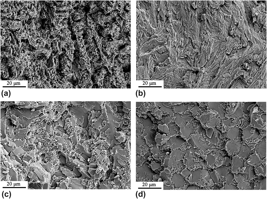
Fracture surfaces after compression testing were observed by SEM, as exhibited in Fig. 5. The Mo0.6 shows a dimple combined with few torn surface morphologies as shown in Fig. 5(a). According to the fractography, the elastic incompatibility contributes to the crack initiation. During the compression testing, the soft FCC phase generated enormous dimples simultaneously retarding the expansion of cracks. Meanwhile, the high strength eutectic phase provides the high compression strength. The incorporation of high strength and high elasticity leads to the excellent mechanical performance. With the increasing Mo content, Mo0.8 transforms to the full eutectic composition. It is observed that the fracture surface extends only along the eutectic lamellae, and the cleavage size is similar to the size of the eutectic cell, as shown in Fig. 5(b). This indicates that the fracture is a quasi-cleavage fracture and it only occurs in the eutectic cells. From Figs. 5(c) and 5(d), it can be found that there are high-density short tear edges and cleavage steps in the Mo1.0 and Mo1.2 alloys, which are the characteristics of the cleavage fracture. It may lead to different types of cleavage fractures because of the eutectic structure and the compound phase. The brittle Cr9Mo21Ni20-type intermetallic phase causes a larger cleavage surface while the eutectic structure leads to a relatively small one. This is the reason that the eutectic structure is composed of the soft FCC phase and hard/brittle Cr9Mo21Ni20-type intermetallic phase. At the same time, the compound phase is the primary phase, and the crack will extend through the brittle phase. This explains the cleavage on fracture appearance of Mo1.0 and Mo1.2, and both of which are cleavage fractures.
Fracture appearance of CoCrFeNiMox: (a) x = 0.6; (b) x = 0.8; (c) x = 1; (d) x = 1.2.

D. Alloy designing anticipation and outcome
For the structural alloys, the microstructure possessing only high strength always suffers from shortness in plasticity. However, the composite structure-like eutectic structure (contains CoCrFeNi and another intermetallic compound phase) combining both plasticity and strength has been proved in many previous studies, like CoCrFeNiTaReference Jiang, Han, Qiao, Lu, Cao and Li31 and CoCrFeNiNb.Reference Jiang, Lu, Dong, Wang, Cao and Li32 On the other hand, it is challenging for us to build the hard phase or an intermetallic compound. There are some factors, which are often used to design HEAs, have received wide recognition, like atomic radius, electronegativity between different contents, and parameters δ and γ. Among these, factor γ using atomic radius in predicts of phase stability serves good in most conditions as Liu reported.Reference Wang, Huang, Yang, Wang and Liu33,Reference Liu, He, Qi, Wang, Zhao, Shang and Zhang34 The parameter of atomic size difference, γ, can be expressed as follows:
 $$\gamma = {{\left( {1 - \sqrt {{{{{\left( {{r_{\rm{S}}} + \bar{r}} \right)}^2} - {{\bar{r}}^2}} \over {{{\left( {{r_{\rm{S}}} + \bar{r}} \right)}^2}}}} } \right)} \left/ {\left( {1 - \sqrt {{{{{\left( {{r_{\rm{L}}} + \bar{r}} \right)}^2} - {{\bar{r}}^2}} \over {{{\left( {{r_{\rm{L}}} + \bar{r}} \right)}^2}}}} } \right)}}\quad ,$$
 $$\bar{r} = \sum\limits_{i = 1}^n {{c_i}{r_i}} \quad ,$$
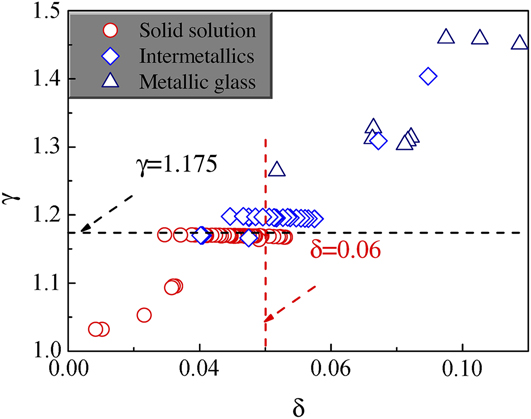
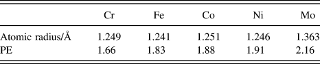
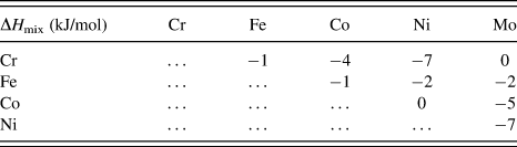
where c i is the atomic concentration of the ith atom, r i is the atomic radius of the ith atom, r L and r S are the radii of the largest and smallest atoms. Previous research of Liu has shown that the alloy system with γ > 1.175 tends to form intermetallic compounds even metallic glass, as shown in Fig. 6. Through the calculation, all the γ of the CoCrFeNiMox alloys in this paper are less than 1.080 (atomic radii shown in Table II). Nonetheless, it should be noted that γ < 1.175 is one of the necessary conditions for determining the solubility of multicomponent alloys but not a sufficient one. Meanwhile, the mixing enthalpy, electronegativity, and electron concentration should also be considered in the designing process. Besides, it can be found that the Pauling electronegativity (PE) of Fe, Co, and Ni elements is close to each other while the difference between Cr and Mo is higher than others (see Table II). Moreover, the atomic sizes of Cr, Co, Fe, and Ni are relatively close but differ from Mo a lot. In addition, there is the highest mixing enthalpy existing between Ni–Cr and Ni–Mo (see Table III). In the traditional metallurgical theory, enthalpy predominantly determined the formation of the compound. More importantly, from the Pickering’s paper, it is clear that enthalpic factors have overcome entropic effects in multiphase HEAs.Reference Pickering and Jones37 The negative ΔH mix promotes the formation of intermetallic compounds, which contains the elements of Cr, Ni, and Mo. The experiment results from XRD have proved the assumption that has been made before. In conclusion, the atomic size difference, electronegativity, and ΔH mix may be the reason for the formation of the Cr9Mo21Ni20-type intermetallic compound.
Statistics of parameter γ and parameter δ from representative experimental results on the phase selection in HEAs.

Atomic radii and PE of the elements.Reference Guo and Liu35

Enthalpies between different contents in CoCrFeNiMox alloys.Reference Takeuchi and Inoue36

To date, of particular prominence are experimental explorations of Prof Yiping Lu et al. All of their studies opened up a new path to the second generation of HEAs. EHEAs have experimentally shown the promise in achieving high-quality industrial scale ingots with uniform composition and structure. The exploration of the CoCrFeNiMox alloy system intends to construct a high mechanical performance structural material, using the “good candidate” eutectic structure. The engineering steel for construction, comprising high strength, high stiffness, good material homogeneity, and isotropy, usually possesses the yield strength around 220–450 MPa. By contrast, the new CoCrFeNiMo0.6 alloy has excellent high strength up to 2051 MPa, which plotted us a vision of future materials.
IV. CONCLUSIONS
A series of CoCrFeNiMox (x = 0.2, 0.4, 0.6, 0.8, 1.0, and 1.2) HEAs with the eutectic structure were prepared by arc melting in an argon atmosphere. Their microstructure and mechanical properties were investigated and the effects of different Mo contents on the microstructure and mechanical properties were studied. Afterward, the following conclusions were made:
(1) A superfine lamellar eutectic structure was obtained in the composition of CoCrFeNiMo0.8. The lamellar spacing is only 110 nm around, thinner than most of the lamellar EHEAs reported before.
(2) With the increase of Mo content, the microstructures of the CoCrFeNiMox HEA shift from a single FCC structure (x = 0.2, 0.4) with dendritic morphology, to a hypoeutectic structure (x = 0.6), then to a fully eutectic structure (x = 0.8) with the mixture of the FCC phase and Cr9Mo21Ni20-type intermetallic compound, and finally to a hypereutectic structure (x = 1.0, 1.2).
(3) With the increase of Mo content, the hardness of CoCrFeNiMox HEAs increases from 172.8 to 763.7 HV. The compressive strength increases from 2051 to 2390 MPa as x increases from 0.6 to 1.2, while the compressive fracture strain decreases from 23 to 5.9%. The CoCrFeNiMo0.6 alloy has a good balance of strength and ductility, of which the fracture strength and strain are 2051 MPa and 23%, respectively.
(4) With the increase of the Mo element, the fracture mode changes obviously from ductile fracture (Mo0.6) to quasi-cleavage fracture (Mo0.8), finally to cleavage fracture (Mo1.0 and Mo1.2).
ACKNOWLEDGMENTS
The authors gratefully acknowledge the financial support from the National Natural Science Foundation of China (Grant Nos. 51601086, 51405215, and 51702143), Liaoning Natural Science Foundation (Grant No. 2015020204), and Doctoral Initiating Project of Liaoning Province Foundation for Natural Sciences, China (Grant No. 201601342).