I. INTRODUCTION
For the past 20 years, the use of digitally assisted techniques to reduce the impact of analog circuit nonidealities has steadily increased and has spread to applications within a wide variety of circuit blocks. In this regard, RF receivers have received comparatively little attention, perhaps due to the relative ease and cost with which design specification could be met. One important example of this is the use of off-chip SAW filters to improve the effective linearity of the receiver by attenuating large out-of-band blocking signals. However, with the recent push toward multimode receivers, the feasibility of incorporating many such filters into a design has plunged. The work described in this paper addresses this trend by proposing a mixed-signal feedforward enhancement scheme to improve the effective out-of-band IIP3 of a SAW-less universal mobile telecommunications system (UMTS) receiver. This paper builds upon the results of [Reference Keehr and Hajimiri1] by describing the key concepts used to set performance requirements on the enhancement circuitry and also contains measured sensitivity results for the complete receiver.
II. SYSTEM-LEVEL CONCEPTS
A) System-level linearization via equalization
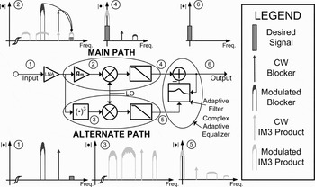
In order to improve the system IIP3 for a SAW-less direct-conversion receiver, the original main path of the receiver is augmented with an alternate feedforward receiver path, as shown in Fig. 1 [Reference Keehr and Hajimiri1, Reference Keehr and Hajimiri2]. The alternate path generates IM3 products in the analog domain at RF and downconverts them to baseband using the same LO frequency as the main path receiver. The IM3 products are then digitized and are used as inputs to an equalizer which cancels the baseband IM3 products in the main path. Hence, a linearization via equalization is accomplished. Generating the IM3 products after the low noise amplifier (LNA) at RF is a crucial feature of this architecture, since it is at this point in the system that the blocker magnitudes are at their largest.
IM3 equalization concept in this work.
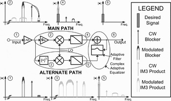
This solution has the advantages of being both power efficient and robust. Since the alternate path must process only IM3 terms, the dynamic ranges of its constituent circuits can be over 10 dB less than in the main path, allowing for significant power savings in its overall design. The time-averaged power dissipation of the alternate path is further reduced by powering it on only when needed, as problematic blocker conditions occur roughly less than 10% of the time. The adaptive tracking nature of the equalization guarantees robustness in the presence of changes in temperature, LO frequency, fading, and changing blocker characteristics.
The idea of adaptively canceling IM3 products has recently been described in a system-level study [Reference Valkama, Ghadam, Antilla and Renfors3], where the alternate path resides completely within digital baseband. For IM3 cancelation to occur in this scheme, the analog-to-digital converter (ADCs) must digitize all possible IM3-producing blockers. For example, in FDD UMTS Region 1 this requires digitizing frequency bands from 1670–1850, 2015–2075, and 1920–1980 MHz (TX band), rendering this scheme unattractive from a power efficiency perspective. In order to overcome this issue, the mixed-signal approach proposed in this work passes only the problematic IM3 products through the alternate path ADCs. Hence, the alternate path ADC and digital baseband sampling rate requirements are no greater than those of the original main path. Furthermore, generating IM3 products at RF prior to downconversion guarantees sufficient IM3 amplitude and signal quality for an arbitrary blocker offset from the receiver LO frequency.
B) Receiver system architecture
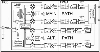
The receiver system architecture described in this paper is shown in Fig. 2. In order to provide a quantitative design objective, the design targets the FDD UMTS Region 1 standard, as it is known for its stringent linearity requirements. It contains a custom integrated front-end in 130 nm RF CMOS, analog baseband circuitry on PCB, and a digital back end implemented on an field programmable gate array (FPGA) platform.
Experimental UMTS receiver architecture.
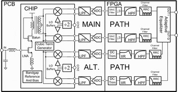
Although it is possible to perform the adaptive equalization in analog circuitry, shifting as much of the signal processing as possible to the digital domain yields several advantages. For example, the behavior of digital circuitry is relatively insensitive to process variations, and the continued scaling of digital processes has made baseband digital blocks power competitive with equivalent blocks in the analog domain.
Considerations specific to modern cellular receivers also factor into the choice of placing the adaptive equalizer in the digital domain. For example, such receivers often implement adjacent channel rejection filters in digital circuitry to assist in multimode reconfigurability. It is therefore best to place the adaptive equalizer after these filters in the digital domain as well in order to ensure that large adjacent channel signals do not interfere in the adaptive equalization.
III. ANALOG CIRCUIT DESCRIPTIONS
A) Main path circuitry
As shown in Fig. 2, the LNA is an inductively degenerated cascode architecture which is terminated by a transformer balun. The balun is followed by folded high-IIP2 mixers [Reference Liscidini, Brandolini, Sanzogni and Castello4], which are capable of functioning under the 1.2 V supply voltage. This choice makes IM2 equalization unnecessary and allows the design effort to focus solely on IIP3 improvement. The mixers are driven by actively loaded Cherry–Hooper LO buffers [Reference Floyd, Reynolds, Zwick, Khuon, Beukema and Pfeiffer5] which are required to drive the rather large mixer switching device gate capacitances.
The main path analog baseband circuitry is implemented with discrete, commercially available components. The baseband low-pass filter is a third-order Chebyshev architecture and is followed by an 8-bit pipelined ADC running at 50 MHz.
B) Alternate path circuitry
The alternate path is a low-power, low-area variant of the main path, with the primary difference being the inclusion of an IM3 term generator. In order to conserve area, the alternate path mixer dispenses with the tuning inductor present in the main path mixer and replaces the single tail current source with two–one for each branch of the circuit. The integrated portion of the alternate path, including IM3 term generator, mixers, LO buffers, and frequency divider consumes 6.7 mA under 1.2 V.
Like the main path, the alternate path baseband circuitry is implemented with discrete components. Part of the alternate path baseband low-pass filters are incorporated into buffers which drive two 8-bit pipelined ADCs running at 16.66 MHz. Together, these off-chip components consume less than 7.6 mA under a 2.7 V supply.
IV. IM3 TERM GENERATOR
A) Design requirements
The IM3 term generator merits additional consideration in specifying its design requirements, as it is an atypical block for use in an RF receiver. An explicitly cubic circuit is desired, as it passes negligible linear terms around the receiver LO frequency. If present, these terms will be treated as error by the adaptive equalizer, potentially reducing the gain of the desired signal or the degree to which distortion terms are canceled.
The IM3 product-to-error ratio (IER) metric [Reference Keehr and Hajimiri6] can be used to quantify the performance impact of the alternate path error on the complete receiver in a simple manner. To see how, consider the output of the alternate path as the output of the adaptive filter in Fig. 1. The equality of the IM3 products in the main and alternate paths is enforced by the adaptive equalizer at the summation node here (1) with any discrepancy in this equality counting toward the IER of the alternate path

After equalization of the IM3 products, the receiver output still contains error due to noise, other IM products, and numerous other effects. As implied by (2) this error power can be decomposed into pre-existing main path error power and error power due to the alternate path. It is assumed that the two error power components are uncorrelated to good approximation and can be referred to the input of the receiver via the main path gain:

Using (1) and (2) the relation of (3) is derived:

As the quantities of (3) regarding main path and total allowable input-referred error should be known prior to the design of the alternate path, (3) can be used to determine the required IER of the alternate path. Another important implication of (3) is the fact that as the power of the IM3-producing blockers varies, the IER quantities of the two paths roughly track assuming that the distortion is dominated by third-order distortion products. Given this, the specification for total input-referred error power in (3) will be met under any blocking conditions to first order if it is met under peak blocking conditions. It can be shown under a reasonable error budgeting procedure that for a UMTS receiver with uncorrected IIP3 = −9 dBm, IERALT under peak blocking conditions (denoted IERALT,PK) should be >31 dB [Reference Keehr and Hajimiri2].
B) Circuit design
Cubic term generators have been used in the past for the predistortion of nonlinear RF transmitter power amplifiers. Reported topologies include those that utilize the third-order Taylor series coefficient of the MOSFET [Reference Shearer and MacEachern7] and those that cascade multipliers in a multistage configuration in order to create polynomial predistorters [Reference Westesson and Sundstrom8–Reference Rahkonen10].
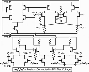
For this work, a multistage IM3 term generator is utilized due to its superior IM3 product-to-noise ratio (INR) properties, which stem from the strong second-order MOSFET nonlinearity and from the fact that the output of the initial squaring circuit is only attenuated with respect to the active device noise floor as the square rather than the cube of the input. The circuit schematic is shown in Fig. 3. The second-order nonlinear operation is performed by a conventional metal-oxide-semiconductor (MOS) squaring circuit in order to avoid the generation of higher-order IM products associated with the nonlinearity of the Gilbert cell current commutating devices.
IM3 term generator schematic.
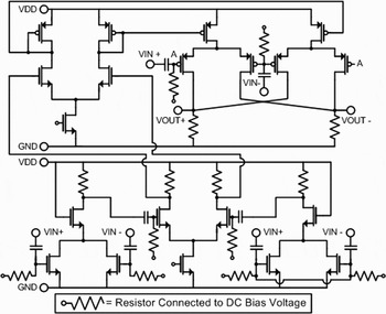
As it produces a single-ended output, the squaring circuit is followed by an active balun, which performs an inductorless single ended to differential conversion. To improve the generator common mode rejection ratio (CMRR), the negative terminal of the balun is tied to a replica squaring circuit whose gate terminals are shorted. This branch only generates common mode signal, which is then rejected by the CMRR of the balun. The final nonlinear operation is performed by a Gilbert cell multiplier. The nonlinearity of the current commutating devices can be mitigated at the expense of the current gain of this stage. However, this gain can be made up in the stages in between the nonlinear operations.
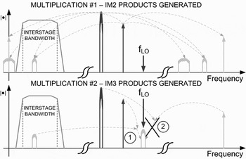
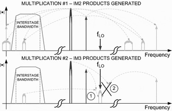
Perhaps the most important aspect of the proposed IM3 term generator is its multistage nature. Only the beat frequency terms of the squaring need to be retained in order to recreate the relevant IM3 products. Hence, the bandwidth of the inter-multiplication circuitry can be substantially smaller than the RF frequencies of the blocker signals, as depicted in Fig. 4. In this case, the gain-bandwidth principle can be used to the designer's advantage, as substantial gain can be applied for less power than if the full IM2 spectrum up to 4 GHz were retained in between nonlinear operations.
Multistage cubing: frequency domain considerations.
V. ALTERNATE PATH POSTFILTER REQUIREMENT DERIVATION
In the alternate path, the out-of-band signals that must be attenuated at baseband are the undesired IM3 products produced by the cubic term generator. One way to determine baseband postfilter requirements is to first bound the total receiver error as a function of the ratio of the alternate path IM3 products under peak blocking to the maximum output error due to aliasing of undesired IM3 products. This quantity is denoted IPKEMAXRALTPF and reflects the fact that the maximum aliased error may not occur under peak blocking conditions. Equation (3) can therefore be modified as in (4), with IERALT,REM,PK denoting the IER of the remainder of the alternate path under peak blocking:

Whether or not a particular postfilter/FS,ADC meets a given IER requirement for the FDD UMTS Region 1 out-of-band blocking test, in which the TX leakage acts as one of two blockers, can be determined by a sweep on the RX and TX LO frequencies. Since for each set {fRX, fTX} there exist two potential CW blockers that result in corruptive IM3 products, a third dimension must be added to the sweep. The following steps are performed for each sweep iteration:
1) For each set {fRX, fTX, fCW} the maximum blocker magnitudes ACW and ATX are determined using the blocker specification and the frequency response of any up-front filtering (e.g. the UMTS duplexer).
2) IM3 product magnitudes are computed at the four IM3 frequencies: {fRX, fTX, fCW, fRX − 3|fCW − fTX|}.
3) The spectrum from part 2 is then downconverted to baseband by fRX and a postfilter model is applied.
4) The effective baseband frequency domain spectrum is aliased to discrete-time baseband by FS,ADC. The energy falling within the RX bandwidth is integrated and used to divide the alternate path IM3 product magnitude under peak blocking. This quantity is then compared to a running minimum and if less, the running minimum is updated. The result of this procedure is the IPKEMAXRALTPF for the given postfilter/FS,ADC combination.
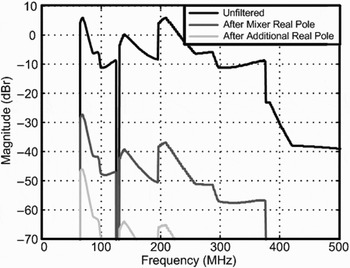
For this project, FS,ADC = 16.66 MHz was chosen to allow the use of a low-power ADC. In this case, if the only postfiltering present were the mixer output pole at 1.5 MHz, then IPKEMAXRALTPF = 27 dB. Adding another first-order pole to the ADC buffer at 8 MHz yields IPKEMAXRALTPF = 46 dB, which meets the requirements of the design of [Reference Keehr and Hajimiri2] with margin. To visually depict the worst-case undesired IM3 products relative to the peak IM3 amplitude as a function of frequency, the procedure described above may be terminated at Step 3, the result divided by the peak IM3 amplitude, and a maximum operator instituted at each frequency bin, resulting in Fig. 5 for the design of [Reference Keehr and Hajimiri2].
Calculated worst-case undesired IM3 product magnitude relative to peak desired alternate path IM3 magnitude versus baseband frequency offset.

VI. DIGITAL EQUALIZATION
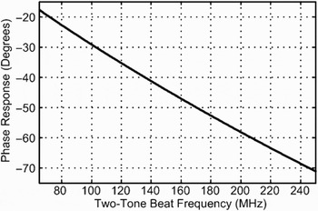
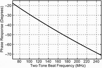
The path equalization implemented in this project is performed in the digital domain and is partitioned into fixed and adaptive portions. This choice stems from the fact that the minimal analog postfilters of the main and alternate path were found to be different in both type and order. Compensating such a known infinite impulse response (IIR) path difference via adaptive equalization is computationally inefficient. Therefore, the fixed equalization consists of a three-multiplier IIR filter in the alternate path. Also lumped into this filter is a coarse group delay compensation. The remaining difference between the two paths is a small random mismatch in the baseband transfer function and a complex DC gain. Because this difference is broadband in the frequency domain, it corresponds to a small number of finite impulse response (FIR) taps required in the adaptive equalizer by the duality principle. The most significant mismatch to be compensated stems from the phase response of the interstage circuitry of the IM3 term generator, shown in Fig. 6. As this phase response is not known a priori, the adaptive equalizer must track and compensate for the additional phase mismatch introduced.
Phase response of interstage circuitry in IM3 term generator.
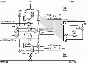
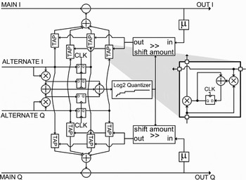
Due to its simplicity and convergence speed, the normalized least mean squares (LMS) (NLMS) algorithm was chosen for the adaptive equalization scheme. The division characteristic of NLMS can be log2-quantized [Reference Oba, Kim and Arai11], allowing the use of a simple barrel shifter as a divider. Although a complex LMS-based algorithm such as NLMS can equalize the phase skew between the main and alternate paths, in general the presence of I–Q mismatch on either path limits the IM3 cancelation. As shown in Fig. 7, this issue was overcome by feeding back the complex corrected signal back to independent I and Q taps on each of the incoming alternate path signals, essentially adding another degree of freedom to the algorithm.
Enhanced NLMS adaptive equalizer block diagram.
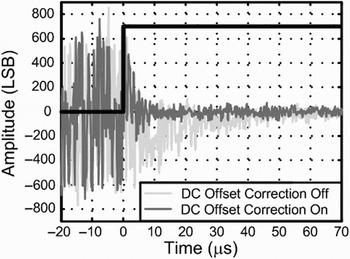
Another consideration is that the adaptive equalizer performance is degraded in the presence of DC offset. To solve this problem, the proposed design includes high-pass filters in the digital domain and DC offset trimming circuitry in the alternate path. Periodic offset trimming must be performed prior to the alternate path high-pass filters, or the step response incurred when enabling the digital portion of the alternate path will result in an exponential error transient at the output, prolonging equalizer convergence.
VII. MEASUREMENT AND PERFORMANCE
The emphasis of this project is to meet the IIP3 requirements implicitly posed by the UMTS out-of-band blocking test, which must be performed while the TX path is operating at maximum output power [12]. For the duplexer [13], the worst-case specified IMD condition, with values referred to the LNA input, is −26 dBm TX leakage at 1.98 GHz, a −34 dBm CW blocker at 2.05 GHz, when the receiver LO frequency is set to 2.12 GHz.
A) Receiver IIP3 measurement results
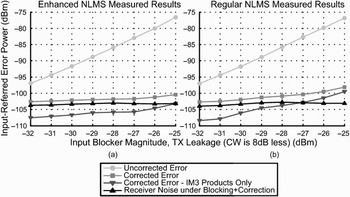
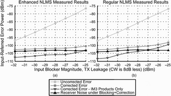
Therefore, under experiment, the receiver is subject to a modified two-tone test, where one of the signals is Quadrature phase shift keying (QPSK-modulated) and set to UMTS standards. Accounting for the 1.8 dB loss of the duplexer and the 3 dB increase in noise margin allowed under blocking conditions, the maximum allowed total input-referred error is −98 dBm [Reference Springer, Maurer and Weigel14]. The results of this test are shown in Fig. 8 and show that in this case under equalization, the input-referred error is −101 dBm. (note: here fCW = 2.05125 GHz, fLO = 2.1225 GHz) Also shown in Fig. 8 are the results of the same test using the canonical NLMS algorithm. A main path quadrature mismatch of about 3° is partially responsible for the higher input-referred IM3 products. All numbers reported and plots shown correspond to the worse of the two digital baseband quadrature outputs under the aforementioned conditions.
Measured modified two-tone performance of the receiver, swept over amplitude.
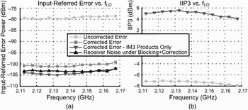
Measured modified two-tone performance of the receiver, swept over LO frequency. At LNA input TX power is −26 dBm, CW power is −34 dBm.
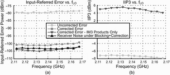
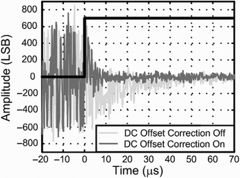
The total input-referred error accounts for thermal noise, gain changes, and distortion products. Removing the effect of main path IM2 products and thermal noise yields a lumped input-referred quantity consisting of all other error sources. This quantity is treated as residual IM3 error, and from its value at the worst-case input blocker magnitude a slope-of-3 line is extrapolated to obtain an effective IIP3 of +5.3 dBm. This is an improvement of 12.4 dB from the uncorrected IIP3 of −7.1 dBm. This test was also performed at all 12 UMTS RX frequencies, with the results shown in Fig. 9. In Figs 8 and 9, the calculated thermal noise of the 50 Ω input impedance is removed to isolate the performance of the receiver circuitry. The convergence behavior of the adaptive equalizer is shown in Fig. 10.
Measured convergence of the adaptive equalization algorithm.
B) Receiver sensitivity measurement results
Although the IIP3 test provides insight as to how nonlinear terms contribute to the input-referred error of the receiver, the actual performance specification that must be met is that of the sensitivity test. In this work, such a test is performed using a specification-equivalent UMTS 12.2 kbps downlink reference measurement channel [12] with both I and Q channels active, with the results comparable to those in [Reference Reynolds, Floyd, Beukema, Zwick and Pfeiffer15]. As part of this test, the digital outputs of the receiver are recorded, then postprocessed offline in MATLAB. The digital receiver outputs are resampled in MATLAB to 30.72 MHz, which is a multiple of the UMTS chip rate of 3.84 MHz.
The theoretical relation between sensitivity and noise figure is given in [Reference Reynolds, Floyd, Beukema, Zwick and Pfeiffer15]. In this work, G = 21.1 dB and IL ≈ 0 dB. Accounting for the 1.8 dB loss of the duplexer, the receiver must achieve BER = 10−3 for DPCH_Ec = −118.8 dBm at the LNA input under typical conditions and DPCH_ Ec =−115.8 dBm under worst-case blocking conditions.
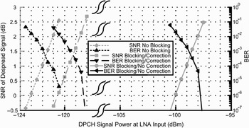
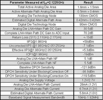
The results of the test are shown in Fig. 11. The fact that BER = 10−3 occurs with despread SNR ≈ 1 dB indicates that the MATLAB postprocessing was performed correctly [Reference Reynolds, Floyd, Beukema, Zwick and Pfeiffer15]. Each point in Fig. 12 represents the average of 4.88 × 105 bits (2000 data frames). These results are in good agreement with those reported in the previous section and in the performance summary in Fig. 12, with the salient result being the 20.7 dB improvement in sensitivity when the alternate path is fully enabled. This corresponds to the roughly 20 dB improvement in input-referred error seen at −26 dBm TX leakage in Fig. 9.
Measured sensitivity results of the receiver.

Measured performance summary of receiver.

C) Additional measurement results
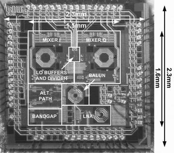
The measured performance summary of the receiver is shown in Fig. 12. Digital power and area numbers are pre-layout estimates derived from a 90 nm bulk CMOS standard cell library with estimated wiring parasitics. Figure 13 shows a die photograph of the integrated RF CMOS front end.
RF CMOS front-end analog die.

VIII. CONCLUSION
This paper describes a UMTS receiver with an integrated RF section in which IM3 products are canceled using a novel mixed-signal feedforward loop. Concepts and methodologies that relate the performance of the alternate feedforward path subcircuits to the performance of the overall receiver are also considered.
ACKNOWLEDGEMENTS
The authors thank F. Bohn for the frequency divider IP and H. Mani and J. Yoo for testing assistance. This project was supported by an NDSEG fellowship and the Lee Center for Advanced Networking.
 Edward A. Keehr (M'02–S'05) received S.B. and M. Eng degrees in electrical engineering from the Massachusetts Institute of Technology (MIT), Cambridge, MA, in 2001 and 2002, respectively. From 2005, he has been working toward a Ph.D. degree in electrical engineering with the Caltech High-Speed Integrated Circuits (CHIC) group at the California Institute of Technology (Caltech), Pasadena, CA. From 1999 to 2002, he held summer internships with QUALCOMM, Incorporated, San Diego, CA as part of the MIT VI-A internship program. From 2002 to 2005 he worked at QUALCOMM as a full-time design engineer specializing in analog and mixed-signal circuits. His current research interests are RF transceiver circuits and architectures.
Mr. Keehr is a member of Tau Beta Pi and Eta Kappa Nu. He was the recipient of an NDSEG Fellowship in 2005 and the Analog Devices Outstanding Student Designer Award in 2006.
 Ali Hajimiri (M'99) received a B.S. degree in electronics engineering from the Sharif University of Technology, and M.S. and Ph.D. degrees in electrical engineering from the Stanford University in 1996 and 1998, respectively. He was a design engineer with Philips Semiconductors, where he worked on a BiCMOS chipset for GSM and cellular units from 1993 to 1994. In 1995, he was with Sun Microsystems, where he worked on the UltraSPARC microprocessor's cache RAM design methodology. During the summer of 1997, he was with Lucent Technologies (Bell Labs), Murray Hill, NJ, where he investigated low-phase-noise integrated oscillators. In 1998, he joined the Faculty of the California Institute of Technology, Pasadena, where he is a professor of electrical engineering and the director of Microelectronics Laboratory. His research interests are high-speed and RF integrated circuits. He is the author of The Design of Low Noise Oscillators (Boston, MA: Springer, 1999) and has authored and coauthored more than 100 refereed journal and conference technical articles. He holds more than 30 US and European patents. He is a member of the Technical Program Committee of the International Solid-State Circuits Conference (ISSCC). He has also served as an associate editor of the IEEE Journal of Solid-State Circuits (JSSC), an associate editor of IEEE Transactions on Circuits and Systems (TCAS): Part-II, a member of the Technical Program Committees of the International Conference on Computer Aided Design (ICCAD), guest editor of the IEEE Transactions on Microwave Theory and Techniques, and the Guest Editorial Board of Transactions of Institute of Electronics, Information and Communication Engineers of Japan (IEICE). He was selected to the top 100 innovators (TR100) list in 2004 and is a Fellow of Okawa Foundation. He is a distinguished lecturer of the IEEE Solid-State and Microwave Societies. He is the recipient of Caltech's Graduate Students Council Teaching and Mentoring award as well as Associated Students of Caltech Undergraduate Excellence in Teaching Award. He was the gold medal winner of the National Physics Competition and the Bronze Medal winner of the 21st International Physics Olympiad, Groningen, Netherlands. He was a co-recipient of the IEEE Journal of Solid-State Circuits Best Paper Award of 2004, the International Solid-State Circuits Conference (ISSCC) Jack Kilby Outstanding Paper Award, two times co-recipient of CICC's best paper awards, and a three times winner of the IBM Faculty Partnership Award as well as National Science Foundation CAREER Award. He is a cofounder of Axiom Microdevices Inc.