I. INTRODUCTION
In engineering practice, the aging, embrittlement and irradiation degradation analysis of structural materials are requisites in the consideration of in-service components. However, the strong volume constraint of irradiated materials restricts the application of a standard test in the field of nuclear engineering. Most of the current conventional techniques are also not accessible to surface engineering due to limitations in terms of the thin surface nanocrystalline layer. Reference Field and Swain1,Reference Lu, Luo, Zhang, Sun, Gu, Zhou, Ren, Zhang, Zhang, Chen, Cui, Jiang, Feng and Zhang2 It is realized that the small-scale techniques could be available methods for mechanical property estimation of micro or nanometer scale materials. Reference Lan and Venkatesh3,Reference Qu, Dabboussi, Hassani, Nemes and Yue4 The hardness, elastic and plastic properties can be extracted from the experimental curves with small deviation. Reference Xia, Bigerelle, Marteau, Mazeran, Bouvier and Iost5 Alternatively, miniature specimen tests hold several advantages over uniaxial tension and compression with bulk materials in the field of novel alloy. Hence, the small-scale techniques have attracted worldwide interest in the past decade.
As a part of the small-scale techniques, the small punch test (SPT) is an effective and promising methodology to test materials extracted from in-service components using a miniature disk sample, which has the merits of being economical and nearly nondestructive.
The load–displacement (L–D) curves, which play a key role in small-scale tests, Reference Oliver and Pharr6 are also considered in the SPT. Well-established evaluation approaches for the elastic modulus, Reference Giddings, Kurtz, Jewett, Foulds and Edidin7 yield strength, Reference Fleury and Ha8 and tensile strength Reference Ma and Yoon9 have been derived. In addition, taking into account the fracture mechanics under different conditions, the feasibility of the SPT for ductile–brittle transition temperature, Reference Kameda and Mao10 creep properties Reference Yang and Wang11 and irradiated damage Reference Mao and Kameda12 is identified.
Development of fracture toughness estimation has been driven by the need for characterizing fracture properties of materials with different grain sizes. Reference Liu, Zhou, Shen and Huid13–Reference Luo, Lu, Zhang, Zhou, Zhang, Dai, Zhang, Zhong and Cui15 The applicability of the SPT in the analysis of crack growth has been examined, especially in the description of J IC for ductile crack extension. Reference Bulloch16 Even at room temperature, there are some nonlinear factors including large plastic deformation, high strain and local damage during the SPT. For the time being, the empirical equations are deduced mainly based on the analysis of the amount of experimental data. Guan Reference Guan, Hua, Wang, Zou and Song17 studied on long term service steel and suggested a linear relationship between J-integral parameter and strain. However, the application of the empirical method is limited and its accuracy also cannot be guaranteed, which greatly hindered the engineering application prospects of the SPT.
The load–displacement data are widely used to determine the elastic–plastic fracture mechanics on a small scale. A simple integration of the load–displacement curve shows the energy in the deformation, which is practicable, and low determinative error. The energy-based method has been proved to be simple and suitable to evaluate the strength of numerous materials. Reference Cao, Qian, Lu and Yao18,Reference Isselin and Shoji19 Based on fracture energy, Ha and Fleury Reference Ha and Fleury20 proposed a model to estimate the SPT fracture, together with micrograph observations. Wang Reference Wang, Shi, Lu, Shi and Ma21 presented a model for J-integral, which is ideally linked to the fracture strain. However, the necking and contact angle are needed to be recorded for the calculation of strain. Although the fracture analysis provides a method which can be universally used, the accuracy of fracture toughness is strongly influenced by measurement errors. So far, there have been few research studies dealing with similar problems.
In this paper, a modified energy method for analyzing fracture toughness of a material was proposed based on the SPT. On the basis of the energy model with strain analysis, the fracture toughness could be predicted using the load–displacement curve with a miniature sample. A three-dimensional finite element model was then established which could discuss the influential factors of the SPT. A combination of experimental and numerical results was obtained to examine the validity of the model. Finally, the influence of geometric sizes on testing results was briefly described comparatively using the finite element model. More importantly, a reasonable relation of geometric parameters was recommended. The results appeared to be meaningful and inspired in the field of large critical engineering components and microscale materials analysis.
II. MATERIALS AND EXPERIMENTAL METHOD
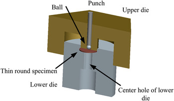
All the tests of Q345R were carried out at room temperature and ambient atmosphere. The SPTs were performed on the INSTRON machine and results were applied to calculate the fracture toughness. The thin plate disk was polished and the size of thickness was Ø10 × 0.5 ±0.02 mm. The specimen was then placed between the upper and lower holders as shown in Fig. 1. It had been proved that the failure of the specimen was mostly related to the dimension of the ball. Reference Fleury and Ha8 Considering the deformation process of the plate, subjected to a biaxial stress, a ball with 1.2 mm radius was used. During the indentation of the ball, the force on the ball was transmitted by the punch and the stroke speed of the punch was 0.5 mm min−1. The displacement and load applied to the specimen were monitored and recorded simultaneously.
Schematic diagram of the SPT.

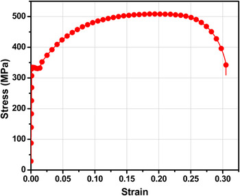
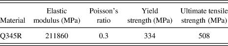
Considering the fracture pattern of Q345R at room temperature, SPTs were conducted to define the J IC, suitable for fracture toughness analysis in many situations. In the following discussion, the fracture toughness of Q345R is measured to be 235 kJ m−2. The mechanical properties of Q345R were studied by a conventional tensile test as shown in Fig. 2 and are summarized in Table I. The value of the hardening exponent is 0.2243.
Tensile testing curve of Q345R.

The mechanical properties of Q345R.

III. NUMERICAL SIMULATION
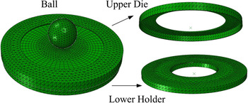
The aim of numerical simulation is to predict the fracture toughness and estimate the influence of geometric factors on the energy method. Detailed 2D simulations about the SPT were performed in early investigation to describe the fracture and initial crack. Reference Yang, Zhou, Ling and Yang22 To imitate the fracture process of the SPT completely, a three-dimensional finite element model in conjunction with the Gurson–Tvergaard–Needleman (GTN) constitutive equation Reference Gurson23,Reference Tvergaard and Needleman24 was established in this study, as shown in Fig. 3. As an appropriate fracture mechanics model for crack initiation and propagation in a ductile material, the GTN model was used as suggested by Guan Reference Guan, Xu, Zhang and Wang25 based on ABAQUS/Explicit. To deliver necessary accuracy, the upper die and lower holder were established and modeled as rigid bodies. The same definition was also applied to the ball. Compared to the edge, finer elements were used in the center region to calculate reasonably in an appropriate time.
Three-dimensional model of the SPT.

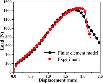
Figure 4 shows the comparison of the experimental and numerical load–displacement curves used to determine fracture toughness. It is noteworthy that two curves are similar. The fine difference may be induced by the thickness deviation in the experiment. Both sets of load–displacement curves exhibit the small general trend of local thickness reduction with deformation followed by necking and the same initial crack. The final failure in necking areas resulted from the growth and coalesce of microvoids is distributed into rings and displays the ductile damage feature. It can be seen that the numerical observations are in agreement with the investigations of experiments. Overall, the rationality and accuracy of the three-dimensional numerical model established in this study are verified.
Comparison of L–D curves from the experiment and finite element model.

IV. RESULTS AND DISCUSSION
A. Modified energy method
In this study, the room temperature corresponding to the upper shelf was selected to analyze the fracture toughness. Derived from the fracture mechanics, the total energy of the SPT in the ductile regime is divided into elastic deformation energy, plastic deformation energy, and fracture energy.
Reference Ha and Fleury20
Two parts are used to estimate the plastic energy corresponding to the deformation of the inside and outside parts of the necking along the contact circle. Several studies have shown that the values of biaxial stresses and strains in the deformation zone exert great influence on the crack propagation.
Reference Bulloch16
However, they are difficult to be measured accurately. Wang
Reference Wang, Shi, Lu, Shi and Ma21
discussed the plastic strain distribution by the average strain (
 $\bar \varepsilon$
) and fractography. The normal average J integral can be expressed as
 $${J^*} = {{{W_t}} \over {2\pi rt}} - {{r{\sigma _0}} \over {2(n + 1)}}{\bar \varepsilon ^{n + 1}}\quad ,$$
where r is the radius of the ball and t denotes the specimen thickness. Wt is the fracture energy from load-displacement curve. J IC is the fracture toughness J integral. At the same time, σ0 and n represent the parameters of material properties for yield strength and hardening exponent.
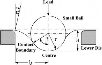
However, the use of micro-measurement does not seem to be suitable for direct determination of strain. The angle of the micro-cracking point of the specimen is too small to be attached accurately. Some equipment is also needed to be used as an essential condition, such as a scanning electron microscope. How to measure the equivalent strain effectively has been the prerequisite and basis for the application of this method. Based on the membrane stretch analysis of Chakrabarty, Reference Yang and Wang11,Reference Chakrabarty26 a model for fracture analysis is observed and shown in Fig. 5. Considering the gradual decrease of strain from the center to the contact boundary, the equivalent strain is defined as the average value of the maximum strain at the center of the specimen and the strain at the moving contact boundary:
 $$\bar \varepsilon = \ln \left( {{{1 + \cos \;\alpha } \over {1 + \cos \;\beta }}} \right) + \ln \left[ {{{2 + 2\cos \;\alpha } \over {{{(1 + \cos \;\beta )}^2}}}} \right]\quad .$$
The model of the energy method.

Different to equivalent strain, it is easy to obtain the displacement of the disc in the experiment and numerical simulation. The expression of the center displacement appears to be a more attractive proposition Reference Yang and Wang11 :
 $$H = r{\sin ^2}\beta \;\ln \left[ {{{\tan (\beta /2)} \over {\tan (\alpha /2)}}} \right] + r\left( {1 - \cos \beta } \right)\quad .$$
Meanwhile, the values of angles α and β have the following geometric form Reference Chakrabarty26 :
 $$\sin \;\alpha = {r \over b}{\sin ^2}\beta \quad .$$
In this study, the radius of the ball is 1.2 mm. A simple mathematical relationship between the equivalent strain and the displacement corresponding to the center of the disc is finally obtained as follows:
 $$\bar \varepsilon = 0.254H + 0.170{H^2}\quad .$$
The unit of displacement here is millimeter. Then, the energy method is modified, which can be achieved by simple measure of displacement. The expression of J integral becomes
 $${J^*} = {{{W_t} - \pi {r^2}t{\sigma _0}{{(0.254H + 0.170{H^2})}^{n + 1}}{{(n + 1)}^{ - 1}}} \over {2\pi rt}}\quad .$$
Due to the local thickness reduction, the localization of plastic damage leads to the decrease of load in the plastic instability phase. Zhang et al. have proposed that the ductility can be found before the failure of the specimen. Reference Zhang, Elwazri, Zimmerly and Brochu27 As an inhomogeneous process, the growth of crack is ductile and gradual. Studies on finite element simulation have reported that a microvoid grows quickly into the stage of accelerated damage and failure happens with the crack propagation in the plastic instability stage. Reference Yang, Zhou, Ling and Yang22 Thus, fracture is defined when a 20% load decrease happens. 28,Reference Turba, Gülcimen, Li, Blagoeva, Hähner and Hurst29
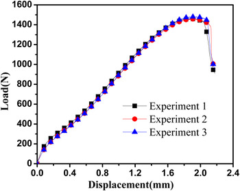
According to the three experimental curves in Fig. 6, the displacement of the center is 2.13 mm and the average fracture energy is 1.91 J. At the same time, the average thickness of three specimens is measured to be 0.52 mm. Then J IC, 257.2 kJ m−2, is deduced from formula (6).
Load–displacement curves of the SPT.

It is worthy to note that the calculated result of SPT is in well agreement with that of conventional test. As a nominal plane stress condition, the smaller thickness leads to higher toughness. Reference Ju, Jang and Kwon30 The size effect may cause the difference between the values obtained by SPTs and conventional tests. Reference Xu and Guan31 Indeed, the flatness deviation and irregular microcracks in materials may also cause the difference in the description of fracture toughness. Overall, based on the load–displacement curve, the calculation of fracture toughness is convenient when the geometric parameters of the experiment are ensured. The energy model reflecting small punch fracture can be suggested as a new method to calculate the fracture toughness.
B. Influence of the geometric parameters
As a quasi-nondestructive method with a small specimen, the size of the experimental apparatus is a notable problem for the SPT. The situation is more complex with fracture toughness as a natural property of the material. Two geometric parameters are discussed to increase the confidence in the reproducible and repeatable results of fracture toughness energy measurement and to analyze the influence of parameters on the energy method.
Previous research studies have proposed that severe damage localization can be found in the contact area between the specimen and the ball, Reference Yang, Zhou, Ling and Yang22 meanwhile, the diameter of the ball plays a key role in the deformation of the disc. Reference Zhou, Zheng, Ling, Hu and Zhou32 For comparison, five models were established with balls of different diameters based on the three-dimensional finite element model built in the previous section.
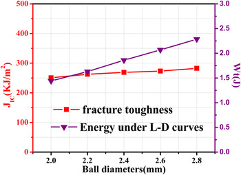
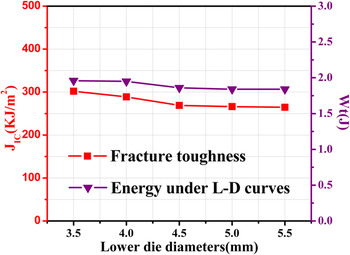
To obtain fracture toughness with different ball diameters, the displacement of fracture must be ensured. A comparison of average strain for different diameters can be seen in Table II. As shown in Fig. 7, the fracture toughness values with different ball diameter values are obtained by replacing the energy parameter in formula (6). It is a known fact that the macroscopic deformation region of ductile materials will expand with the increase of the ball diameter. The load bearing capacity of the specimen increases as the region under the load–displacement curve increases. Therefore, it is easy to find that the absorbed energy has a trend to increase with the augment of ball diameters. The same behavior can be observed in the character of fracture toughness. In light of this result, the finite element model of the SPT in the present work is realistic and adequate. In the present work, fine difference can be found in the calculation results when the ball diameter is <2.6 mm. A similar conclusion can also be found in the analysis of the diameters of the center hole in lower die, as shown in Fig. 8 and Table III. When the diameter of the lower die reduces to 3.5 mm, a sudden increase of material fracture toughness will happen. The reason for this is that the assumption about average strain is not appropriate when the lower die diameter is too small or the ball diameter is too large. The elastic–plastic deformation of the specimen in the fracture zone is serious with the decrease of the lower die diameter during crack propagation. Reference Wang, Shi, Lu, Shi and Ma21 The strain of the nonconstant region cannot be ignored. The deformation energy should be recalculated with the change of fracture process zone. Fortunately, the deviation only happens with the extreme dimension.
The calculation of average strain with different ball diameters.

Influence of ball diameters on fracture toughness and W t.

Influence of the center hole diameters of the lower die on fracture toughness and W t.

The calculation of average strain with different lower die diameters.

It should be noted that the calculated values of finite element simulation are obviously greater than the experimental results. This mentioned error can be explained by microdamage. In the experiment, the stable crack initiated and propagated gradually in the plastic bending regime. Reference Ju, Jang and Kwon30 The microcrack and damage would gradually extend in the deformation and lessen the fracture toughness. However, the finite element model was based on the assumption that the material was isotropic. Reference Yang, Zhou, Ling and Yang22 Overall, the models are reasonable and can optimize the accuracy of load–displacement curves to analyze the energy method.
In general, the influence of an individual geometric parameter on the ductile fracture toughness is less based on the above model. It is proved that, due to the intrinsic property of the material, the change of geometric parameters will bring in minor errors for fracture toughness. However, the interplay between ball diameter and lower die diameter suggested that a reasonable relation of geometric parameters is important. In this paper, we recommend the diameter of the center hole in the lower die should be 1.5–2 times that of the ball.
V. CONCLUSIONS
This paper presents a modified energy method of the SPT to assess the fracture toughness that can be successfully applied in the field of nuclear engineering and many other in-service materials. To overcome the disadvantage of calculation for average strain, we assume that equivalent strain is the average value of the maximum strain at center and the strain at contact boundary. According to the membrane stretch analysis, the relationship between strain and displacement in the deformation is achieved. The experimental reproducibility of the SPT has been obtained at room temperature. By using the load–displacement curves, the energy method is used to calculate the fracture toughness for ductile materials.
The three-dimensional finite element analysis of the SPT has been completed which can give accurate prediction about load–displacement curves in all stages. Moreover, the influence of geometric parameters on the proposed method is discussed. When the ball diameter is too large, the prediction of fracture toughness is not accurate. The same conclusion can also be found with the decrease of lower die diameter. Based on the fracture mechanic analysis, it is recommended that the diameter of the center hole in the lower die should be 1.5–2 times that of the ball.
The results demonstrate that fracture toughness of ductile materials can be successfully evaluated using the modified model of the SPT. This method, being both simple and economical, can be used in further life prediction of in-service materials with small volume or thin surface nanocrystalline layer.
ACKNOWLEDGMENTS
The authors are grateful to the National high technology research and development plan (863 plan) of China “Grant No. 2012AA040105”.