NOMENCLATURE
VARIABLES
ALT Orbital = orbital altitude
ALT Reentry = atmospheric re-entry altitude
ANCREW = crew number
I sp = specific impulse
L/D = lift-to-drag ratio
OEW = operating empty weight
OWE V = operating weight empty from volume budget
OWE W = operating weight empty from weight budget
R N = nose radius
S pln = planform area
S wet = wetted area
TOGW = take-off gross weight
V e = re-entry velocity
V total = total volume
W = weight
W/S = wing loading
Greek Symbols
τ = Küchemann slenderness parameter
γ = flightpath angle
ΛLE = leading-edge sweep angle
Acronyms
AVD = Aerospace Vehicle Design Laboratory
CD = conceptual design
CMDS = complex multi-disciplinary system
DB = database
AVDS = Aerospace Vehicle Design Synthesis
GHV = Generic Hypersonic Vehicle (AFRL project)
KB = knowledge base
LEO = low Earth orbit
LRV = lifting re-entry vehicle
MDA = multi-disciplinary analysis
MDO = multi-disciplinary optimisation
SAV = space access vehicle
WB = wing body
1.0 INTRODUCTION
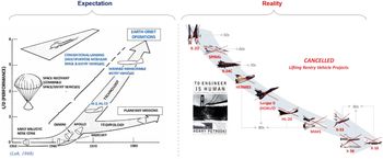
THE design process of any aerospace system can be generically broken down into three distinct phases: (1) conceptual design (CD), (2) preliminary design (PD) and (3) detailed design (DD). The CD phase is the first step in the design cycle, where a system’s primary requirements are used to define a conceptual blueprint and starting baseline for the physical system. Since these primary requirements can be fulfilled by distinctly different systems, the primary goal of the CD phase is to assess alternative, feasible solution concepts and identify the best case or baseline design that will be further refined throughout the PD and DD phases. To this effect, the initial exploration and visualisation of the design solution space continuum become a key deliverable to the designer. It is apparent that the early gestation phase of the design life cycle clearly lays the foundation for the success or failure of the evolving product. Failure to quantify the available design solution space topography correctly from the outset may lead to severe forecasting risk consequences, in that the project may be conditioned towards failure right from the beginning (selecting a poor performance or sometimes non-feasible baseline design). In Fig. 1, the graphics on the left from 1968 (reproduced from Loh(Reference Loh1)) show how lifting re-entry vehicles (LRVs) have been considered as a suitable option for Earth-orbit missions, while those on the right show the track record of cancelled and failed LRV projects over half a century.(Reference Rana and Chudoba2) Although there are multiple aspects associated with the failure of such complex projects, one contributing reason for project failure is the incorrect initial identification of a feasible and well-performing baseline configuration during the early conceptual design (CD) gestation phase (see for example the ill-conditioned baseline configuration choice for HOTOL and NASP). After all, that is essentially what correct aerospace forecasting is all about, being able to predict whether a mission–hardware–technology combination can generate a viable product or not.
Expectation for LRV designs from the early space days and examples (reality) of failed LRV programs.

The author has conducted a comprehensive review of 60 LRV programs worldwide in reference (Reference Rana3), indicating that the published CD documentation for LRV vehicles tends to be notoriously deficient. Consequently, the initial critical reasoning outlining the overall forecasting process, and therefore underlying the quality of mission–hardware–technology projecting decisions, tends to be severely under-documented. A review of past to present CD synthesis methodologies(Reference Rana3) indicates that existing CD methodologies approach the design process in a rather non-integrated manner. In particular, they lack the fundamental capability of total system convergence, which is a key feature to enable screening of the available mission–hardware–technology design solution space continuum. Such synthesis methodology deficiency tends to result in the selection and development of an incorrect baseline concept.
The current study introduces an adaptation to AVDS, a state-of-the-art conceptual design synthesis methodology and software under development since 2002 at the AVD Laboratory. AVDS approaches system design by facilitating total flight vehicle convergence for a multitude of flight vehicle configurations (generic capability), thereby enabling screening and thus visualisation of the feasible design solution space topography. This capability enables the decision-maker to identify the correct baseline design with regards to the program’s needs, thereby ensuring the development of a technologically and economically competitive vehicle.
The first section of this paper provides an introduction to the overall study. The second section provides an overview of past-to-present CD synthesis methodologies and software implementations. This literature review is presented to (a) identify major shortcomings of existing CD synthesis methodologies and software implementations, followed by (b) a specification for the next-generation AVDS space launch vehicle synthesis capability. In this regard, the first subsection of the second section summarises the overall problem that this paper addresses, while the second subsection provides the solution logic that facilitates answering the problem. The third section describes AVDS from a systems perspective, in particular its unique paradigm shift for CD mission–hardware–technology forecasting work. The fourth section focusses on a verification case study, for which the 1957 Boeing X-20 Dyna-Soar data-rich legacy LRV development program has been selected. This case study section addresses the primary synthesis logic and the disciplinary analysis methods selected, facilitating the multi-disciplinary execution of the framework. The fifth section offers an interpretation of the sizing results, followed by the sixth and final section providing a summary and conclusions.
2.0 CONCEPTUAL DESIGN SYNTHESIS SYSTEMS
A synthesis methodology is a multi-disciplinary framework and the primary toolset that is used during the conceptual design (CD) phase. The synthesis methodology parametrically establishes the conceptual feasibility of prospective flight vehicles and generates a solution space topography of potential design concepts for specific mission requirements. In the context of aerospace vehicle design, the synthesis process systematically distinguishes feasible from non-feasible complex flight vehicle systems by considering the interdisciplinary interactions among the primary design disciplines and their underlying gross design drivers.(Reference Coleman4) A design synthesis methodology includes a set of disciplinary analysis methods that model the primary design disciplines (aerodynamics, propulsion, performance etc.), while the synthesis process logic integrates those analysis methods into an iterating and total-system converging cohesive system modelling environment. The true value of the synthesis environment is its ability to converge individual total flight vehicle systems to the mission objective and visualise the emerging solution space topography consisting of a continuum of feasible designs.(Reference Chudoba and Heinze5)
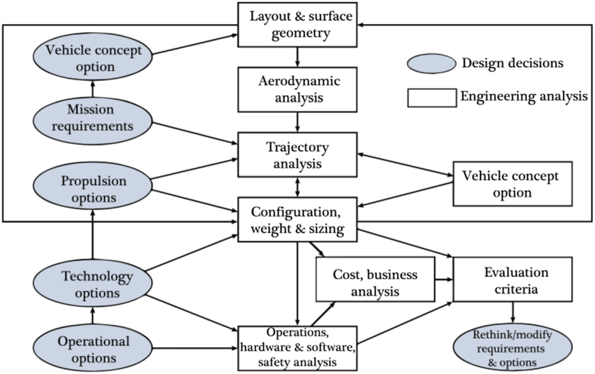
NASA space launch vehicle design process by Rowell and Korte.(Reference Rowell and Korte6)

An example of the multi-disciplinary conceptual design process implementation is shown in Fig. 2 from a National Aeronautics and Space Administration (NASA) technical memorandum report by Rowell and Korte.(Reference Rowell and Korte6) This process figure identifies two primary design functions: (1) design decisions (critical system decisions such as the selection of the propulsion system, material, configuration etc.) and (2) engineering analysis (mathematical, analytical and parametric computation of the involved design disciplines). These two design process functions highlight how decisions are made during the CD phase and their overall influence on the technological and operational aspects of the prospective flight vehicle. (Note that this implementation example does not show iteration or, in particular, system convergence.) Clearly, the emphasis is on early design decisions that must be correctly forecasted for informed decision-making during the project gestation phase. Consequently, the ability of the initial forecasting capability to substantiate design decisions is mostly desired by the chief engineer and strategic decision-makers alike, as it directly indicates the overall success or failure potential of the project and program.
The AVD Laboratory at the University of Texas at Arlington (UTA) is a research environment that focusses on advancing the state of the art in conceptual design practices for aerospace flight vehicle systems. Through the cumulative and continuing research efforts of several generations of researchers, the AVD Laboratory has been developing and expanding the AVDS synthesis methodology and software since 2002. As a result, an extensive foundation of valuable data and knowledge applicable to conceptual design synthesis has been generated.(Reference Czysz, Bruno and Chudoba7) Several previous AVD Laboratory research members have studied and reviewed past-to-present synthesis methodologies in detail. The current research study applies lessons learned from these reviews that entail the synopsis and key features of 126 representative synthesis approaches. A detailed summary of these reviews can be found in reference.(Reference Rana3) To this effect, the next section provides an overview of existing aerospace synthesis methodologies and the major drawbacks identified. This discussion describes the primary problem that is answered by the current research paper.
2.1. Review of existing synthesis capability – problem definition
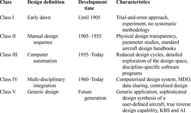
Chudoba(Reference Chudoba8) provides a historical review of flight vehicle design synthesis systems and tracks the evolution of design methodologies from legacy handbook design processes to modern-day computerised synthesis systems. A hierarchy of five classes of synthesis systems is defined based on the level of increasing proficiency at integrating multi-disciplinary effects (Table 1). The classification scheme adopted is based on the modelling complexity and the multi-disciplinary integration capacity of the existing flight vehicle synthesis approaches.
Class I methodologies address the trial-and-error approach applied at the dawn of aeronautics. During this initial era, flight vehicles were poorly understood from a design perspective without any systematic design methodology in place. Class II design methodologies are based on an improved physical understanding of the flight vehicle’s interdisciplinary complexities. These were the first parametric processes and methodologies to assemble individual analysis disciplines into design handbook methodologies and manual slide-rule-type processes.
The transition from class II to class III approaches represents the first step towards computer application and automation in the design environment. These early design methodologies focus on discipline-specific analysis and computer integration but lack multi-disciplinary integration, which still has to be accomplished manually.(Reference Lovell27)
Five generations of evolution of CD synthesis approach by Chudoba(Reference Chudoba8)

Class IV synthesis systems involve multi-disciplinary integration of the disciplinary analysis, but they tend to be limited in application to one specific vehicle implementation. Most synthesis systems leading up to class IV are applicable to subsonic/transonic aircraft, while only a few address SAVs. Synthesis systems such as Czysz’s Hypersonic Convergence(Reference Czysz9) and PrADO-Hy(Reference Heinze10) are identified as significant class IV methodology implementations.
This assessment leads Chudoba to define the requirements for the next generation of class V methodologies with a focus on generic synthesis capability, which is identified as a design process rather than a design tool. In this regard, the focus here is on developing the capability over its application.
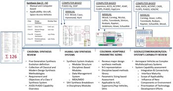
Continuing with Chudoba’s review of synthesis approaches, Huang,(Reference Huang11) Coleman,(Reference Coleman4) Gonzalez,(Reference Gonzalez12) Omoragbon(Reference Omoragbon13) and Oza(Reference Oza14) have conducted additional surveys of existing aerospace vehicle synthesis approaches. These reviews cover a total of 126 synthesis approaches including the complete spectrum from legacy textbook design approaches (e.g. Torenbeek,(Reference Torenbeek15) Roskam(Reference Roskam16) etc.) to computerised synthesis systems (e.g. PRADO-Hy,(Reference Heinze10) FLOPS,(Reference Mccullers17) and SSSP(18)). See Fig. 3 for a summary of CD synthesis system reviews by the AVD Laboratory.
CD synthesis system reviews by the AVD Laboratory.

Based on these reviews, the following conclusions provide a summary of the major drawbacks of the traditional and current design methodologies (class II to IV):
1. The majority of existing synthesis systems have been developed for fixed-wing aircraft design applications. Only a few, selected design synthesis systems can effectively address highly integrated flight vehicles such as the hypersonic cruiser, hypersonic accelerator (SAV) and hypersonic glider (space re-entry) classes.
2. Synthesis is the primary integration capability that is tasked with closing (converging) the total system through iteration and convergence proof. Overall, very few synthesis systems deliver the crucial mathematical proof of total system design convergence.
3. From aircraft to SAV applications, most synthesis implementations are not able to identify or visualise the design solution space topography by representing a grid of converged and thus feasible total system designs.
4. Most synthesis implementations tend to have a common disciplinary analysis structure but non-transparent multi-disciplinary computational implementations. There is a lack of transparent multi-disciplinary integration quality applied at the conceptual design level.
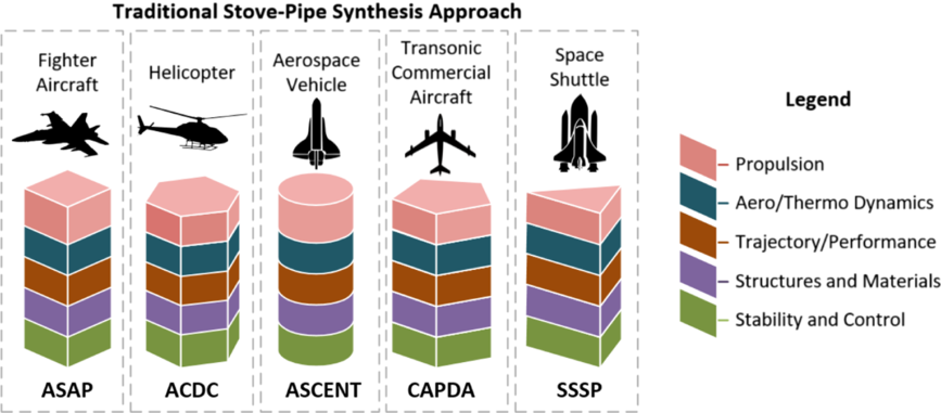
5. Existing synthesis systems have been predominantly developed for a specific application (e.g. transonic commercial transport implementing the tail-aft wing-body configuration). This implies that a range of initial assumptions and methods are encoded during the development of the synthesis system. Since most legacy systems have been developed for their specific application right from the outset, their application is by definition limited to only those applications (a stovepipe situation). Figure 4 presents five multi-disciplinary synthesis methodologies with their application-specific domain, showing the stovepipe approach implementation dilemma. Note that a specific color represents a design discipline, while the different shapes in each approach signify different analysis methods in each application for the same discipline. None of these synthesis approaches are applicable to another flight vehicle category for the needed comparison purposes. As a traditional class IV system is applied over time, it remains stagnant and thus limited to the initial application boundaries. No generic (meaning configuration-independent) synthesis system has been developed from the outset for aerospace vehicle conceptual design with consistent modeling of a range of mission and configuration alternatives for performance or benefit assessment comparison purposes. Clearly, this capability is required to enable true comparisons of dissimilar mission–hardware–technology implementation options via the assessment of all available design solutions independently of hardware, configuration and technology specifications.
Figure 4.Representative examples of existing class IV synthesis approaches showing the prevailing stovepipe approach scenario.


2.2. State-of-the-art design synthesis system capability criteria definition – solution logic
The previous subsection recognised the major deficiencies in the suite of existing aerospace synthesis implementations. This subsection defines requirements towards a best-practice synthesis capability that provides a first-ever configuration-independent mission–hardware–technology forecasting process and software. These characteristics act as guidelines for enhancing the solution specification for the AVDS process and software, overall truly shifting the status quo of today’s CD community. The next-generation class V synthesis capability clearly represents an advance beyond the current CD state of the art. The following discussion provides an overview of its most pertinent features:
1. Generic: The primary focus when developing a class V synthesis capability is on the underlying development process, strategy and logic. Class V synthesis is rooted in a generic logic, thereby enabling applicability to a wide array of flight vehicle categories (mission–hardware–technology permutations) instead of one specific vehicle class.
2. Consistency: Class V synthesis capability must be modular in structure and developed such that it can be consistently applied to different types of aerospace vehicle classes. The modular framework must be established such that the synthesis capability can sustainably adapt to and grow with every new application.
3. Convergence: Parametric sizing is a vital capability implemented in a mathematical framework to integrate the range of necessary disciplinary methods in a multi-disciplinary process. The true challenge in developing a sizing methodology is the formulation of a robust convergence criterion. The primary function of the convergence criteria is to implement the mathematical checks to confirm that an individual design iteration has been completed and a feasible design solution obtained. To implement such a sizing methodology, distinct computational algorithms are required for managing a library of discipline-specific analysis methods and the multi-disciplinary integration process.
4. Transparency: The database management system (DMS) is a crucial computational element that enables a class V synthesis system to model a range of dissimilar aerospace configurations transparently. For each aerospace vehicle application, the DMS generates a consistent customised synthesis code. Distinctly different mission–hardware–technology aerospace configurations can thus be compared by comparing the results generated by consistent synthesis codes, each modeling a specific configuration implementation. The DMS regulates the flow of information within the parametric sizing execution, controls the data transfer between involved disciplinary modules and implements disciplinary methods in the multi-disciplinary framework. A robust data management system has been central to the AVDS prototype class V synthesis capability. This DMS approach enables the development and execution of the synthesis process in a transparent manner. For each mission–hardware–technology aerospace configuration implementation, a custom synthesis code/executable is newly generated, thereby permitting maximum transparency of parametric information flow to the designer. Clearly, this approach avoids the non-transparency pitfall of decades-old legacy codes maintained by the aerospace design community.
5. Solution space: The class V synthesis system screens and thus generate a comprehensive design solution space topography during the CD phase, consisting of various design configurations and concepts, each showing the potential for satisfying the required mission objectives. A design solution space topography is assembled from specific converged mission–hardware–technology configuration and concept design points. Clearly, this requires that the class V capability systematically screens and visualises feasible (converged) point designs for relevant mission–hardware–technology configurations and concepts assembled into a two- or three-dimensional topography visualisation. The emerging solution space or feasibility topography is scrutinised using comparative criteria to access prospective baseline designs satisfying the cost–risk–time objective function.
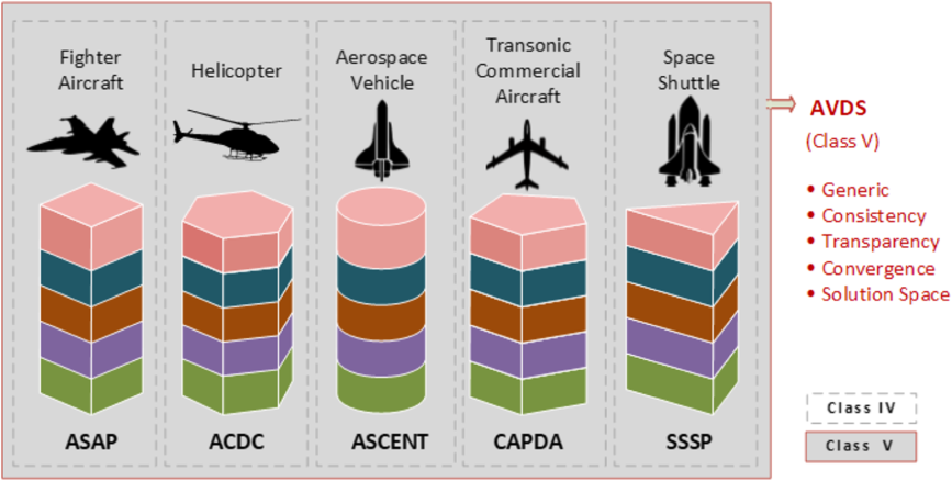
Figure 5 shows how AVDS overarches the existing stovepipe approaches and graphically illustrates the difference between representative class IV approaches and the new class V synthesis implementation. As shown in the legend, the dotted lines mark bounds of earlier synthesis approaches (called the stovepipe approach or the class IV category). The outer box represents the AVDS (a class V capability), which can be used for all the applications, as it can develop customised synthesis codes specific to the problem and is not limited to any one application. Also listed are characteristic features that define the fundamental requirements for the class V generic synthesis capability as implemented with AVDS. The following section focusses on AVDS by providing a detailed introduction to the primary system logic, software attributes and significant capabilities of this prototype system.
A class V (AVDS) synthesis capability is generic in application and transcends the limitations pertinent for an individual traditional stovepipe application.

3.0 AVDS: A NOVEL DESIGN SYNTHESIS APPROACH
The AVD Laboratory at the University of Texas at Arlington has developed and is applying a proprietary prototype conceptual design synthesis tool named AVDS. This application has evolved over more than a decade and provides a unique capability of creating custom-tailored sizing codes specific to the problem at hand. AVDS distinguishes itself from a class IV capability primarily in the manner in which it automatically generates project-specific synthesis codes. For example, if a class IV CD tool is a machine that manufactures a product (a design for a particular type of flight vehicle), then AVDS (a class V CD tool) is a factory that custom-generates those machines (class IV CD tools) by incorporating iteration, convergence, screening and solution-space visualisation into each custom-generated synthesis code.
The AVDS software architecture is divided into three primary layers, details of which are shown in Fig. 6. The Graphical User Interface (GUI) and database layers are executed in Microsoft Access (using the VBA and SQL programming languages). The analysis layer consists of MATLAB files comprising parametric, analytical and empirical methods for individual design disciplines. The MS Access implementation acts as a warehouse for the independent modules (vehicle database, vehicle knowledge base, methods library and process library) that form the basic building blocks of any synthesis code. The user selects problem-specific components from this warehouse-type setting. These blocks are then combined following a best-practice step-by-step process to create a unique synthesis architecture consisting of MATLAB files. Once this synthesis architecture is created, it is executed to size the specific design application, outside and independent of the MS Access framework. In this manner, the MS Access implementation acts as a generic pre-setup platform while the MATLAB-based sizing architecture is the problem-specific post-setup design execution platform. AVDS is the overarching total system and process that combines both the pre-setup MS Access and post-setup MATLAB architecture portions. This implementation demonstrates a fundamental paradigm shift from how design has been approached traditionally to date and is recognised as a class V synthesis capability.
AVDS: system overview.

This latest incarnation of the AVD Laboratory synthesis methodology and software AVDS has been developed through the collaborative research effort of Gonzalez,(Reference Gonzalez12) Omoragbon(Reference Omoragbon13) and Oza.(Reference Oza14) AVDS has been applied to demonstrate the aforementioned unique capability as a part of the AFRL Summer Faculty Fellowship Program by Chudoba and Gonzalez.(Reference Chudoba19) In the context of this AFRL initiative, the AFRL generic hypersonic vehicle (GHV) study has been used as the primary AVDS verification case study. The AVDS results showed general agreement with the AFRL-generated GHV reference data. The AVDS development process, GHV verification results and further details of the system can be found in Gonzalez,(Reference Gonzalez12) Omoragbon(Reference Omoragbon13) and Oza.(Reference Oza14)
3.1. AVDS – system description
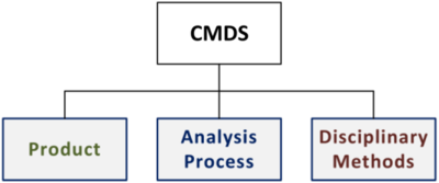
The development of AVDS followed the fundamental logic of a Complex Multi-Disciplinary System (CMDS) which is composed of three primary functional information classes: (1) Product, (2) Analysis Process, and (3) Disciplinary Methods (Fig. 7). The three primary components of a CMDS are discussed next, enabling us to characterise a design synthesis system.
AVDS is developed following CMDS principles.(Reference Gonzalez12)

3.1.1. Product
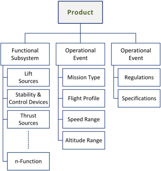
The first component, the Product, refers to the physical representation of the flight vehicle being modelled/designed. Three general considerations describe a product: (1) what it does, (2) when it does it, and (3) the limitations or requirements for its operation. In the context of an aerospace system, the Product component comprises three parts; (1) Functional Subsystem, (2) Operational Events, and (3) Operational Requirements (Fig. 8).
Functional concept of primary component 1: Product.

These three parts are defined as follows:
1) Functional Subsystem: individual hardware components added to achieve one or more primary function(s)
2) Operational Event: an operational attribute that is time dependent
3) Operational Requirement: an operational attribute that is time independent
With this implementation, AVDS creates a functional model of the flight vehicle in terms of the subsystem hardware, flight trajectory and mission profile. It must be noted here that, at this point, the vehicle model is a shell vehicle of involved subsystems and mission attributes. For instance, at this point, it is specified whether the propulsion system to be used is rocket-based or of scramjet type, while the sizing of the engine, amount of fuel required etc. are not known at this point. Another key aspect to note is that, while modelling the flight vehicle, it is specified which subsystems will be functional in which trajectory segment. An example of this aspect is, if a trajectory segment is for unpowered glide, then the propulsion module (thrust source) will not be active during this particular segment. In this manner, the flight vehicle model is developed in conjunction with a model mission profile.
3.1.2. Analysis process
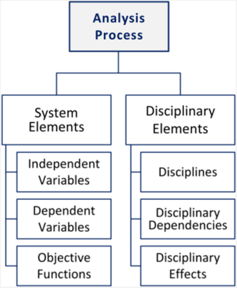
The second primary information class of AVDS is the Analysis Process, which defines the overall parametric framework of the multi-disciplinary sizing process. Figure 9 shows the conceptual build-up of the Analysis Process, which is broken into two classes of information: System Elements and Disciplinary Elements.
Functional concept of primary component 2: Analysis Process.

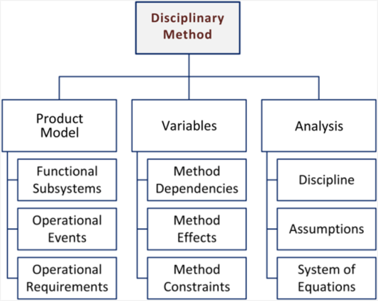
Functional concept of primary component 3: Disciplinary Methods.

The System Elements block is composed of the System Process Variables, the most important variables that control and regulate the flow of data in the MDA framework. They make up the objective function and are iterated until the objective function is satisfied, thus providing the mathematical system convergence proof or feasibility of the overall solution. The Disciplinary Elements define the primary design disciplines and their top-level output variables. The top-level output variables of a discipline are only those which are required by other disciplines and hence define interdisciplinary dependencies and effects.
3.1.3. Disciplinary method
The third and final primary component of AVDS is the Disciplinary Method. Figure 10 shows the functional decomposition of this component into three main parts along with the description of each constituent. This component primarily relates to the ability of AVDS to handle and store individual disciplinary methods in the system. The product model part of the method describes how it is associated with the Product component, identifying at which product node the disciplinary method is applied. The Disciplinary Variables define the involved variables that the method is made up of and further specify the input and output variables for each method. The Analysis part of the Disciplinary Method component contains the system of equations or the empirical data that connect input and output variables.
3.2. AVDS – system execution
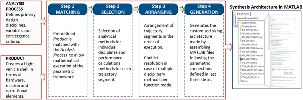
The AVDS system is assembled and managed in MS Access, where it is executed in four sequential steps to finally create a customised flight vehicle sizing code. The four executable steps are: (1) Matching, (2) Selecting, (3) Arranging, and (4) Generation. These four steps create a parametric map of parameter connections that specify how the information flows during the sizing execution. At the end of the fourth step (Generation), AVDS produces a sizing code architecture which is custom-tailored, and stitched from disciplinary method MATLAB files that are connected via the parametric connections defined in AVDS. The following text provides a brief description of each step:
1. Matching: The first step matches the Product (defining the hardware, mission, and operational aspect of a flight vehicle) with the Analysis Process (defining the design disciplines and parametric structure of the sizing logic). It must be noted here that, before executing this first step, the Product and the Analysis Process must already be defined by the user. The matching is done to ensure that the selected Analysis Process has all the required disciplines that can model all functional aspects of the Product.
2. Selection: Once the vehicle and analysis process template is matched, the next step (Selection), provides the user with a list of disciplinary methods that produce the output variables. This is a user-dependent step in which the user selects the methods that are consistent with the vehicle and analysis process. For the case study presented in this paper (in the next section), the disciplinary methods have been created specific to the architectures, so they are created by the user. Once a method is created in the system, it can be used in any new architecture given that it satisfies the limitations imposed by the selected Product and the Analysis Process.
3. Arranging: Once the methods are selected for each design discipline, the execution process moves to the next step (Arranging), in which the trajectory segments are arranged in the sequence of the mission profile. This arrangement stitches the performance analysis methods in a sequence such that the total weight ratio and fuel fraction for the entire mission trajectory can be calculated. This step also ensures that no two methods are being executed for the same flight phase for the same disciplines. This provides the user with options to specify the filter for how and where each method must be executed. Such is specifically done for the aerodynamic methods, where the methods specific to the Mach number range are assigned.
4. Generation: The next step is the final step of the process, where a variable-based check is implemented for the entire product arrangement, disciplinary methods and variables such that no inconsistent variable selection occurs. Once this check is found to be satisfied, AVDS has arranged all the disciplinary variables in a sequential order of execution following the logic defined in the Analysis Process. At the end of this step, the system selects the MATLAB analysis files for each discipline (that are stored on a server) and stitches them together in the variable execution logic defined in the MS Access system. Thus, the final MATLAB-based flight vehicle sizing architecture is generated.
At this point, the user has a problem-specific custom-build sizing framework in the form of a MATLAB file architecture that does not require any further input or interaction from the MS Access-based implementation. Thus, the MS Access implementation can be considered as the pre-setup portion of the AVDS, and the MATLAB-based customisation–synthesis–architecture–execution as the post-setup portion. The user at this point starts to input the required disciplinary values as demanded by the disciplinary methods and problem specification. The overall execution process and four steps are presented in Fig. 11, which provides a brief description for each execution step. A crucial point to note here is that the four steps and the sizing architecture generation are generic in nature and thus are independent of any specific product type. Clearly, AVDS provides a true generic design synthesis capability that is applicable to any flight vehicle category. The next section describes a SAV case study that demonstrates the application of this next-generation AVDS sizing capability.
AVDS execution process flow to generate a custom synthesis system architecture.

4.0 CASE STUDY EXECUTION
As mentioned above, AVDS has been applied to design a scramjet-based hypersonic vehicle during the AFRL-GHV study.(Reference Chudoba19) The author has also applied the AVDS system to lifting-body and wing-body re-entry vehicle studies, where more than 1100 LRV or hypersonic glider concepts have been designed, details of which can be found in reference (Reference Rana3).
Since these studies lie beyond the scope of the current paper, this section demonstrates the execution of AVDS for a legacy re-entry vehicle to be sized by the custom-built synthesis architecture. The vehicle selected for the case study, the Boeing X-20 Dyna-Soar, stems from a late 1950s legacy USAF LRV program. This case study illustrates the capability of AVDS to develop a customised sizing architecture for a specific flight vehicle, in this case, a rocket-powered lifting re-entry hypersonic glider, to be executed for a specified mission. Since the X-20 program provides a data- and knowledge-rich history, this case study is also advantageous as a verification case study for the sizing results obtained. It should be noted here that, prior to this application, AVDS has been primarily used and verified for scramjet-based hypersonic cruise vehicles. Overall, the X-20 case study thus demonstrates the flexibility of AVDS to generically and consistently address different types of flight vehicle categories, independent of mission, configuration or application limitations.
Dyna-Soar program phases and vehicle layout.(Reference Rana, Mccall, Haley and Chudoba28)

The X-20 customised synthesis system developed using AVDS is explained in this section via the following three subsections, one for each primary component of a CMDS: (1) Product, (2) Analysis Process, and (3) Disciplinary Methods. The first subsection focusses on the product to be modelled that is specified for the architecture. This involves developing a functional model of the physical vehicle, creating a mission profile model that defines the major trajectory segments to be analysed and matching the functional attributes of the vehicle to the trajectory sections (i.e. which functions are operational in which particular trajectory segments). The second subsection then describes the analysis process or the synthesis sizing logic that is composed of primary design disciplines arranged in an executable order. The third subsection provides an overview description of the disciplinary methods used for the analysis of individual disciplines.
4.1. Product
4.1.1. The vehicle: Boeing X-20 Dyna-Soar
The X-20 Dyna-Soar was the first operational vehicle initiative to apply all the available 1950s high-speed knowledge into a single program with practical application. The main objective of the Dyna-Soar program was to obtain hypersonic flight data and experience to develop a space bomber with a global range. The program was to be developed in multiple stages, with each stage’s mission requirements becoming sequentially more demanding (Fig. 12). Phase 1 of the program was aimed at delivering a test vehicle as a testbed for the boost-glide operation. This stage of the program was supposed to be a proof of concept, validating the feasibility of the technology and hardware selection for a low Earth orbit (LEO) re-entry mission. The second stage of the program would deliver a sub-orbital mission-capable vehicle with limited capabilities over a restricted range of around 5000 nmi. This stage was a single-person vehicle. The third and final stage of the program aimed at developing the first-of-its-kind hypersonic, global range, strategic bomber/reconnaissance system. This variant would attain orbital speeds and perform single- and multi-orbit missions. The orbital version was envisioned to have multiple variants with single- or multi-crew capacity.(Reference Godwin20)
The name Dyna-Soar stands for dynamic soaring, a flying technique commonly used by birds to save energy whilst maximising range. The X-20 was designed to use this method to gain lift by crossing between air masses of different velocity due to changing atmospheric density layers. The X-20 was supposed to be the first space plane in an era that was later dominated by re-entry capsule designs operated under the Mercury, Gemini and Apollo programs.(Reference Rana, Mccall, Haley and Chudoba21) In contrast, the X-20 hypersonic glider was a horizontal landing system implementing a fuselage-low delta-wing design (Fig. 12). Stability and control during re-entry would be provided by winglets and elevons; there was no conventional vertical tail. The general layout of the vehicle consisted of the pilot compartment followed by the equipment bay used to house the payload (scientific and reconnaissance equipment, weapons etc.). The orbital variant had an extended pilot compartment allowing for a four-person mid-deck. The vehicle retained the upper-most rocket stage from the launcher (Titan IIIC) for in-orbit manoeuvres and de-orbital burns for re-entry. This propulsion module, called a trans-stage, was jettisoned prior to descent into the atmosphere.(Reference Geiger22)
4.1.2. Mission profile
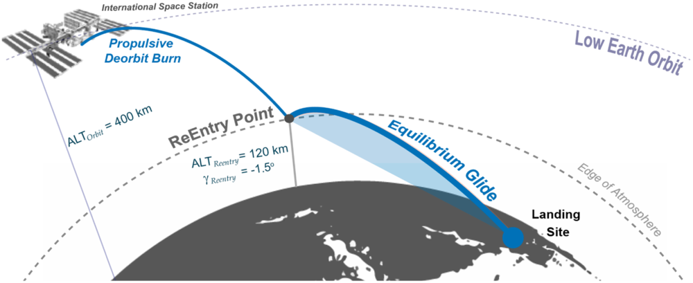
For the present study, an International Space Station (ISS) resupply mission is the model mission selected for the sizing activity. This mission is a suitable representative for the X-20 vehicle, as the orbital version of the Dyna-Soar was developed as a glider vehicle able to execute a lifting re-entry trajectory following a de-orbit burn.(Reference Godwin20,Reference Geiger22) In these regards, the chosen ISS resupply mission lies within the capability and performance domain of the X-20 vehicle. The mission begins, as shown in Fig. 13, with the vehicle in a circular parking orbit at an altitude of 400km. The vehicle de-orbits from this altitude, using an onboard liquid rocket propulsion system. The de-orbit burn is instantaneous with a retro burn angle of 180°. After de-orbiting, the vehicle follows a Keplerian orbit until atmospheric re-entry. Atmospheric re-entry is assumed to occur at 120km altitude and −1.5° flight path angle. After re-entry, the mission profile is a generic LRV equilibrium glide profile (see Galman(Reference Galman23) for a discussion on equilibrium glide). No atmospheric skip occurs. The re-entry analysis assumes a small flight path angle and small flight path angle variation conditions, which are standard assumptions in the equilibrium glide analysis as seen in Galman(Reference Galman23) and Eggers.(Reference Eggers, Allen and Neice24)
LEO re-entry mission profile selected to design the case study.(Reference Rana, Mccall, Haley and Chudoba26)

4.2. Analysis process: AVDS sizing process logic
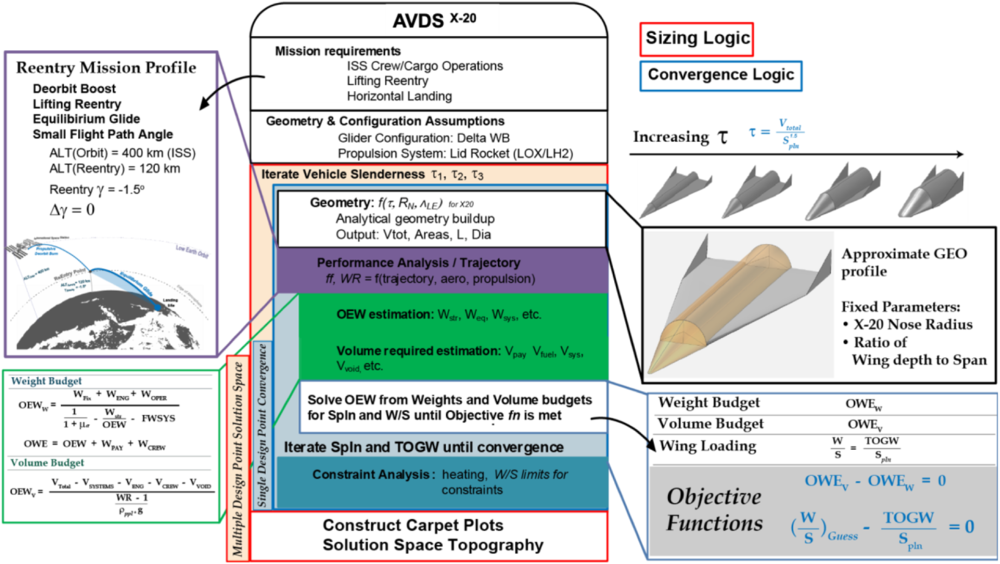
The multi-disciplinary synthesis logic is applied to size the vehicle and identify the first physical characteristic estimates of fundamental variables such as weight, volume and physical dimensions. Such information is vital to any feasibility investigation. The sizing methodology (AVDSX-20) used for this study is based on the constant mission sizing logic Hypersonic Convergence by Czysz.(Reference Czysz, Bruno and Chudoba7,Reference Czysz9) The sizing logic and related analysis discipline arrangement is shown using the Nassi–Shneiderman diagram in Fig. 14.
Sizing and convergence logic of the synthesis systems developed using AVDS.(Reference Rana, Mccall, Haley and Chudoba28)

This is a first-order sizing application where the most critical design parameters are identified and employed to develop a design solution space of converged design points. This sizing application is a multi-disciplinary analysis toolset where key technology parameters are recognised. These parameters are used to characterise the whole vehicle system, allowing technology forecasting studies, mission exploration studies, design feasibility studies and more. The sizing-based forecasting approach is used to measure the design with current-day available industry capability versus future technology. In the process, the system identifies if there is any specific requirement which can cause the program to fail during later stages (show-stopper assessment). The complete MDA methodology developed in the present context is a modular structure implementation, composed of individual disciplinary analysis methods and the integration process.
The sizing logic is implemented through the Analysis Process component of AVDS, where the fundamental independent and dependent system process variables are initially defined. The independent variables (planform area and wing loading) are the initial input into the system which are fed into the geometry methods to start the sizing analysis. The disciplines are then executed in the following order: geometry, aerodynamics, propulsion, performance, weights, and volume. The dependent variables (TOGW and total weight estimate from the weight and volume method) are calculated at the end of each sizing execution sequence and are used with the independent variables to define the objective function. This process is iterated until the objective function is satisfied and process convergence is achieved using the calculated primary disciplinary results.
The vehicle’s planform area and wing loading are the primary input variables that are iterated until a converged design solution is achieved. The designer provides an initial guess estimate of these variables, which feeds into the MDA framework shown in Fig. 14. The geometry module acts as the ‘gearbox’ of the synthesis system where the vehicle’s geometry is defined in terms of the vehicle slenderness parameter (τ = V total/S plan1.5) such that the geometry shape can be scaled efficiently using just τ, which takes account of area and volume effects collectively. Thus, for a fixed planform area, increasing τ results in an increase in the overall volume and thus produces a thicker/stouter vehicle. The geometry module then passes the vehicle’s geometric characteristics to the aerodynamic analysis method, which calculates lift and drag values for the specified mission profile. Next, the aerodynamic results are passed to the propulsion module, which calculates the required thrust for a selected propulsion type. The performance calculation method is then applied to determine the fuel fraction and the vehicle’s mass ratio for the overall mission trajectory. The results from the geometry, aerodynamics, propulsion and performance matching modules are used to assess the vehicle’s weight and volume. In this manner, for a given vehicle slenderness parameter (τ), the initial estimates of vehicle planform area and wing loading are iterated through the total design process until the available weight and volume equal the required weight and volume. The algebraic sizing process solves for weight and planform area simultaneously by converging the weight and volume for a given set of design variables. At this point, a single vehicle concept (for a fixed τ) has been sized. This process is shown in the internal blue box (labelled “Single Design Point Convergence”) in Fig. 14. As the system is sized for one particular τ, by iterating the independent variables, an outer sweep of τ then provides a means to develop a solution space of converged vehicles that are sized to the same mission. This process is shown in the external red box (labelled “Multiple Design Point Solution Space”) in Fig. 14.
The sizing code is created by AVDS as a modular structure of the MATLAB script files for disciplinary analysis. A central input file stores the required disciplinary and mission variable input values. These variables are also iterated with τ via the outer sweep loop to size multiple vehicle concepts and develop the design solution continuum visualised as the solution space topography.
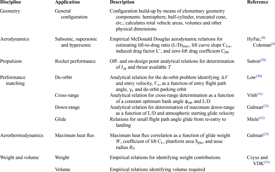
Summary of disciplinary methods used in X-20 MDA

4.3. Disciplinary methods
The disciplinary method references and their respective input/output variables are stored in the Disciplinary Methods component of AVDS. They are applied through the Analysis Process of the AVDS platform into an MDA framework as explained in the previous section. The following five primary disciplines are engaged for sizing the vehicle in the current case study:
1. Geometry: Calculates the overall geometric properties of the vehicle. The method used for modeling the geometrical shape of the X-20 vehicle is composed of the first-order analytical geometric relations of standard shapes (cone, cylinder, ellipse etc.). The analytical model’s validity is verified against the physical dimensions of the legacy X-20 data (Table 2).
2. Aerodynamics: Calculation of primary aerodynamic coefficients (CL, CD, L/D, etc.) for subsonic, supersonic and hypersonic flight regimes based on empirical data derived for already trimmed LRVs. This method takes into account the stability and trim of the vehicle for the selected mission trajectory (Table 2).
3. Propulsion: Calculation of thrust available for an off-the-shelf rocket engine (X-20 transtage) based on standard textbook method (Table 2).
4. Performance matching: Calculation of primary performance values for the de-orbit and equilibrium glide flight path based on analytical performance studies (Table 2).
5. Weights and volume budget: Calculates overall weights and volume budgets of the primary hardware components based on parametric relationships. The method takes into account the thermal protection system (TPS) and structural implications (Table 2).
The details and references of the disciplinary methods used for this case study are summarised in Table 2.
5.0 SIZING RESULTS
This section provides the results for the execution of the X-20 sizing architecture which is developed by combining elements described in the previous section. The sizing architecture generation process using AVDS has been explained earlier.
5.1. Single-point convergence
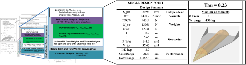
A single-point convergence design study is executed first. The single point design is evaluated for a fixed slenderness value of τ = 0.23, calculated based on original X-20 three-view drawings. The mission constraints of a single crew and payload of 450 kg are adopted from the X-20 vehicle data.(Reference Godwin20) The convergence logic iterates the planform area and wing loading until the objective function is satisfied. The result is a converged vehicle solution, details of which are shown in Fig. 15.
Single design point solution obtained by iterating S pln and W/S while converging on gross weight and volume.

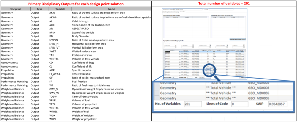
The vehicle’s defining variables are shown in Fig. 15, identifying the overall vehicle configuration characteristics and performance. Between all the analysis disciplines engaged, the sizing process calculates 27 primary output sets. Each one is a variable that is iterated for every combination of planform and wing loading. Note that there are a total of 201 variables involved in a single sizing iteration, including those used internally within all the disciplines (Fig. 16). Given the large quantity of data generated, it is impractical to illustrate and discuss all results. Therefore, only the most significant variables representing the overall design solution and those that provide a holistic representation of the case study are presented through the solution space topography as discussed in the next subsection.
Total number of internal and external variables involved in a single point convergence.

5.2. Multi-point design solution space
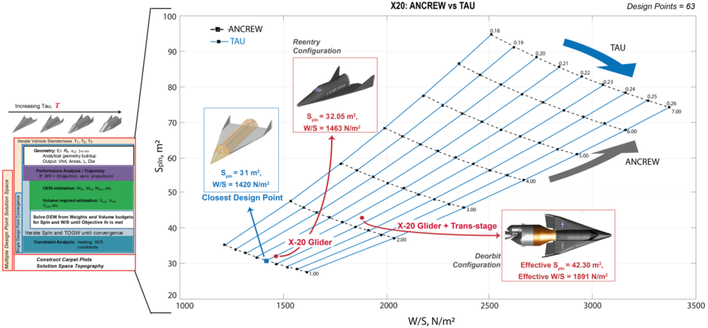
As mentioned above, the Küchemann slenderness parameter τ defines and controls the overall geometrical properties of the vehicle.(Reference Czysz, Bruno and Chudoba7) For a single point design solution, the planform area is iterated along with the wing loading to converge the sizing process. Further iterations of τ and other mission parameters are implemented next to develop a solution space continuum (solution space topography) consisting of individually converged total vehicle design points. The overall design solution space provides a carpet plot visual that is of significant value for the decision-maker during the early design phase. Figure 17 shows the overall solution space generated for the X-20 vehicle by iterating τ and the crew size (parameter ANCREW).
Single design point solution is iterated for τ and crew members (ANCREW) for developing a design solution space. Each design point is a converged vehicle concept.

As seen in this figure, the carpet plot consists of a total of 63 design points where each vehicle represents a converged solution similar to the case shown in the previous section. Each design point accounts for approximately 200 variables and produces 27 disciplinary outputs. Since the actual X-20 vehicle jettisoned the trans-stage before re-entry, the total X-20 vehicle had two operational configurations. Both of these configurations, the X-20 glider and the glider with trans-stage, are shown (by the red dots) to lie within the sized solution space. Further, it can be seen that the X-20 glider lies on the τ = 0.22 line and slightly above the crew size equal to one case. The closest design point sized to the mission constraints of the original X-20 glider is also indicated on the carpet plot. This nodal point on the carpet plot is the closest solution concept to the actual X-20 vehicle that was sized in the multi-point iteration and represents the delta between the solution found by the code and the actual X20, which is within an acceptable margin for the conceptual design results.
5.3. Constraint implementation
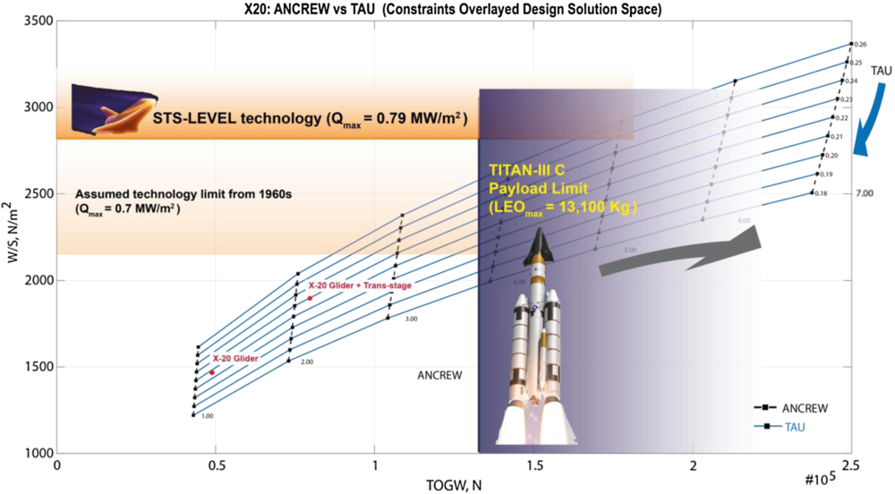
Following the generation of the solution space carpet plot, the next step is to identify the limiting constraints that define the feasible design options. Two principle constraints are considered: (a) maximum heat flux and TPS, and (b) lift-off vehicle max payload. These constraint limits are implemented and visualised in Fig. 18.
Constraints applied based on TPS system technology and launch vehicle (Titan-IIIC) payload limitations.

The constraints for the maximum heat flux (Q max) during the equilibrium glide section of the trajectory are provided by Galman(Reference Galman23) as a function of the wing loading and nose radius (see equation (4) in Galman(Reference Galman23)). The TPS technology level identifies the constraining regions in terms of wing loading on the vertical axis. First, the TPS technology level of the Space Shuttle(Reference Jenkins25) is plotted and found to affect the current developed solution design space for the X-20. Assuming a reduced technology level, one equivalent to that of the X-20 program era, it can be seen in Fig. 18 that the solution space decreases significantly. The TPS technology level limits the feasible design space to a maximum crew size of 3 and τ = 0.23.
The second constraint corresponds to the payload limit of the Titan-IIIC launch vehicle. The Titan-IIIC was selected as the primary launch vehicle for the X-20 glider in the early 1960s.(Reference Godwin20) The Dyna-Soar program was cancelled before the first flight of the launch vehicle. As can be seen from Fig. 18, the launch vehicle ability also reduces the overall solution space significantly. However, although the feasible design solution space reduces significantly after application of those constraints, both configurations, the X-20 glider and the glider with trans-stage, still lie comfortably in the feasible design space. The second phase of the X-20 program was planned with a higher-performing mission profile and increased crew member capacity. Consequently, vehicles with higher payload capability would not lie in the solution space shown in Figs 17 and 18.
6.0 CONCLUSION
The primary goal of this study has been to describe a prototype generic class V synthesis design capability, AVDS. The primary capability criteria factors defined in Section II.B identified five key aspects of a state-of-the-art class V synthesis capability and act as the enabling solution logic for the AVDS. These five criteria require that the AVDS system be generic and consistent in the application, must have a transparent structure, provide a proof of convergence and produce a design solution space topography of feasible concepts.
The logical framework of the synthesis system has been described, providing an overview of the primary components of AVDS. The execution process provides information on how AVDS develops a problem-specific synthesis architecture. This feature makes AVDS analogous to a factory that can develop customised machines (a customised synthesis architecture) which then creates a specialised product (flight vehicle design concepts).
Following this general system definition, the X-20 case study has been executed to demonstrate how AVDS satisfies all five capability criteria of a class V synthesis implementation. As mentioned above, the AVDS system has been applied to design hypersonic cruise vehicles(Reference Gonzalez12) before this SAV application. Besides, the AVDS system has also been applied to design a range of lifting-body(Reference Rana, Mccall, Haley and Chudoba26) and wing-body(Reference Rana, Mccall, Haley and Chudoba21) re-entry vehicles. These applications (that lie outside the scope of the current publication) prove the generic capability of the AVDS system independent of the application constraints.(Reference Rana3) Since the customised synthesis architecture is executed outside and independent of the pre-setup MS Access framework, this implies that the complete AVDS process is consistent in applications for all categories of flight vehicles. The MS Access framework acts as a sophisticated DMS which keeps track of all the involved variables, disciplinary methods, synthesis process and the convergence logic. This provides a high level of transparency for the system that enables the information flow and process to be tracked in real-time execution. The X-20 case study shows the capability of the AVDSX-20 architecture (and consequently the AVDS) to effectively converge the sizing process and design a vehicle concept that is proven to be physically feasible and thus meets the required mission objectives. Further, the X-20 case study also shows the ability of AVDS to develop a solution space continuum or topography by trading off a mission parameter (number of crew in the X-20 case) to size multiple converged vehicles. A total of 63 converged design points have been obtained for the X-20 type vehicle, which leads to the development of an unbound solution space continuum. The selected constraint implementation is superimposed to define the feasible design space. It further acts as a validation of the correctness of the AVDS generated results, where the legacy X-20 design is shown to lie within the feasible solution space.
Overall, AVDS represents a prototype novel class V capability. The modular structure of the system is deliberately created such that it will become more advanced with further applications for other flight vehicle categories. Each new application will add to the library of products, analysis methods and synthesis processes. The AVD Laboratory continuously enhances AVDS to become a best-practice forecasting process, environment and software.
ACKNOWLEDGEMENTS
The authors would like to thank past and present AVD researchers for their contributions towards the development, advancement and application of the AVDS system.