Introduction
Pseudoelliptic bandpass filter responses are preferred for modern microwave transceiver frontends because of their ability to achieve a sharper transition from passband to stopband [Reference Snyder, Mortazawi, Hunter, Bastioli, Macchiarella and Wu1]. This sharp transition is possible because of the availability of finite frequency transmission zeros (TZs) in elliptic and pseudoelliptic responses, thus enabling better frequency selectivity. When low loss/high-power-handling capability is a concern, such filters are often based on waveguide technology because of the high quality factor achievable in waveguide implementation [Reference Boria and Gimeno2]. Many ways to realize TZs in waveguide technology have been proposed in the literature, including cross-coupling between non-adjacent resonators and/or the use of dual, triple, or quadruple mode cavities [Reference Boria and Gimeno2–Reference Guglielmi, Jarry, Kerherve, Roquebrun and Schmitt8]. Pseudoelliptic response can also be realized using the extracted pole synthesis method [Reference Rhodes and Cameron9] or by using frequency dependent coupling sections as inverters [Reference Amari and Bornemann10]. A more recent approach to generate pseudoelliptic characteristic that has been developed in the last decade is to create multiple paths for energy flow using non-resonating modes [Reference Snyder, Mortazawi, Hunter, Bastioli, Macchiarella and Wu1, Reference Bastioli11]. These non-resonating modes are either propagating or evanescent at the filter passband. The additional energy paths implemented by the non-resonating modes can lead to the realization of arbitrarily placed finite frequency TZs while still keeping the inline configuration. The earliest work in this regard involves asymmetric irises in rectangular waveguide [Reference Arndt, Duschak, Papziner and Rolappe12, Reference Guglielmi, Montauti, Pellegrini and Arcioni13] to implement TZs but in this structure, the non-resonating mode dies down very quickly along the length of the waveguide, thus limiting the flexibility in positioning of TZs. This limitation is eliminated by utilizing an enlarged width waveguide cavity with the resonating mode of TE201 [Reference Iguchi, Tsuji and Shigesawa14–Reference Macchiarella, Gentili, Tomassoni, Bastioli and Snyder16]. A more compact singlet structure (A singlet [Reference Amari, Rosenberg and Bornemann17] is a structure that realizes a reflection zero along with a TZ.) can be implemented using TM110 mode as the resonant mode [Reference Rosenberg, Amari and Bornemann18]. Further compactness is achieved by combining the idea of TM dual-mode cavity with the concept of non-resonating modes [Reference Bastioli, Tomassoni and Sorrentino19–Reference Pelliccia, Cacciamani, Tomassoni and Sorrentino21].
The above techniques require folded configurations or some arrangements that increase the cross-section size relative to the standard direct-coupled-cavity waveguide filters. For the applications where this increase in cross-section is a concern, inline waveguide filters capable of providing pseudoelliptic characteristic can be realized using the methods proposed in [Reference Tomassoni, Bastioli and Snyder22–Reference Bastioli, Marcaccioli and Sorrentino25]. Dielectric pucks appropriately placed in a propagating rectangular waveguide can be used to realize pseudoelliptic filters [Reference Tomassoni, Bastioli and Snyder22, Reference Tomassoni, Bastioli and Snyder23]. However, this arrangement requires fine positioning of each dielectric puck at a particular angle in the waveguide making the fabrication process cumbersome. TZs can also be implemented using an inline filter configuration by using dual-post resonators [Reference Tomassoni and Sorrentino24]. The dual-post resonators having different post heights can realize a TZ below the passband, while rotated dual-post resonators can be utilized to produce a TZ in the upper stopband. These dual-post resonators have to be fabricated separately and then push fit into the waveguide, again making the fabrication process tedious and less repeatable. Rectangular ridge resonators based waveguide filters [Reference Bastioli, Marcaccioli and Sorrentino25] maintain the inline filter configuration and are capable of producing TZs in the upper or lower stopbands, using rotation, or offset properties of the rectangular ridge resonators. This configuration has the advantage of ease of manufacturing because it involves only computer numerical control (CNC) machining of solid aluminum block and no additional components are required, making it economical and repeatable for production purposes. However, a TZ realized using offset of ridge resonator has limited flexibility because of the physical constraints of waveguide.
In this paper, we propose a new class of singlet capable of realizing pseudoelliptic inline waveguide filters, using non-resonating modes. The singlet is comprised of a transverse rectangular ridge resonator with asymmetric irises, as shown in Fig. 1. The ridge resonator is at the fixed location at the center of the waveguide and is transverse to the waveguide axis. The asymmetric irises can be configured to achieve a TZ either below (Fig. 1(a)) or above the passband (Fig. 1(b)), without involving any rotation or offset of the ridge. Since, no rotation of the ridge is involved, this will allow the usage of more efficient electromagnetic (EM) simulation tools like FEST3D [Reference Melgarejo, Cogollos, Guglielmi and Boria26], in addition to the more general purpose segmentation based (finite element or finite difference) EM simulators like HFSS or CST. Since, the ridge resonator is fixed and centered at the waveguide axis with no offset, thus no practical machining limitations are encountered. No offset, enables the ease of machining by having ample space for the milling tool on each side of the ridge. The dominant mode TE10 of the rectangular waveguide forms the non-resonating mode enabling the direct source to load coupling, thus creating an alternate path to realize a TZ. The ridge is excited by higher-order modes of the waveguide particularly TE20 mode (and to a lesser extent by other similar symmetry waveguide modes like TE40, TE60, etc.) which are a consequence of the discontinuity created by asymmetric irises at the input and output of the singlet. The input/output couplings to the resonator can be different from each other and are achieved by dimensioning each asymmetric iris. Input/output coupling to the resonator can be controlled by dimensioning each asymmetric iris without any additional elements.
Transverse rectangular ridge resonator with asymmetric irises (a) on the same side and (b) on the opposite sides.

The singlet structures of [Reference Bastioli, Marcaccioli and Sorrentino25] are capable of producing TZs in the upper or lower stopbands, using rotation or offset properties of the rectangular ridge resonators. The slant ridge is used to realize a TZ in the upper stopband. In other words, the authors of [Reference Bastioli, Marcaccioli and Sorrentino25] used the rotation angle as the design variable to implement a TZ at the desired location in the upper stopband. However, this slant ridge cannot be analyzed using the more efficient EM simulation tools like FEST3D, or mode matching methods, and thus requires the general purpose but much slower simulation tools such as HFSS and CST. In contrast, the singlet structures proposed in this work, make use of a ridge that is always centered and transverse with respect to the waveguide axis and utilize asymmetric irises to realize TZs either above or below the passband. This enables the proposed structure to be simulated using FEST3D. Additionally, in [Reference Bastioli, Marcaccioli and Sorrentino25] offset of the transverse ridge from the waveguide center axis is used to implement a TZ in the lower stopband. Note that this offset range is limited because of the physical constraints of the waveguide. This limitation is more pronounced if the filter passband is located closer to the lower recommended frequency range of the standard waveguide. On the other hand, the singlet structures proposed in this work do not involve any offset of the ridge from the waveguide center axis, thus allowing ample space for machining tools on both sides of the ridge resonator. Same side irises are then used to excite the fixed centered ridge to realize the TZ at the desired location in the lower stopband.
Singlet: asymmetric iris coupled transverse rectangular ridge resonator
The ridge can be modeled as a length of parallel plate line open circuited at both ends [Reference Bastioli, Marcaccioli and Sorrentino25]. The ridge resonate at the frequency f 0, when the length ℓ is

where λ0 is the free space wavelength at f 0.
Being a half-wave length section of an open-circuited parallel-plate line, the transverse ridge has positive electric field maximum at the one end and a negative maximum at the other end [see Fig. 2(a)]. The TE10 mode having a maximum electric field at the center with diminishing fields at the side walls [see Fig. 2(b)], thus cannot excite the resonant mode of the ridge. The symmetry is broken by introducing asymmetric irises, which then excite the higher-order modes particularly TE 20 mode [see Fig. 2(c)], that has a field configuration aligned to the ridge mode and thus can excite the ridge resonator.
Cross-sectional views showing electric field distribution for (a) fundamental resonant mode of transverse ridge inside a rectangular waveguide, (b) TE10 mode in a rectangular waveguide, and (c) TE20 mode in a rectangular waveguide.

Thus, in the presence of asymmetric irises, the dominant mode of the rectangular waveguide forms the source to load coupling (J SL), while the higher-order modes like TE20 couples energy to or from the resonator (J S1 or J 1L), thus forming a singlet.
The 3 × 3 normalized coupling matrix of the form shown below can be utilized to represent the response of the proposed ridge resonator structures:

The coupling and routing diagram for this singlet structure is shown in Fig. 3.
Coupling and routing diagram of the proposed transverse rectangular ridge-based singlet.

Different filter responses can be achieved from the proposed singlet structure by modifying the structure.
Transverse rectangular ridge resonator with no irises
Here a rectangular ridge resonator is placed transverse to the waveguide axis [see Fig. 4(a)]. For symmetry reasons explained above this ridge resonator will not be excited by the dominant TE10 mode of the rectangular waveguide and thus behaves as just a capacitive discontinuity. This case does not create any pole or any TZ, i.e. J S1 = J 1L = 0. Source to load coupling is not zero J SL ≠ 0, because of the TE10 mode of the waveguide.
Transverse rectangular ridge resonator with (a) no irises, (b) same side irises, and (c) opposite side irises. Dotted arrows: source to load coupling (J SL). Solid arrows: input and output to ridge couplings (J S1, J 1L).

Transverse rectangular ridge resonator with asymmetric irises on the same side
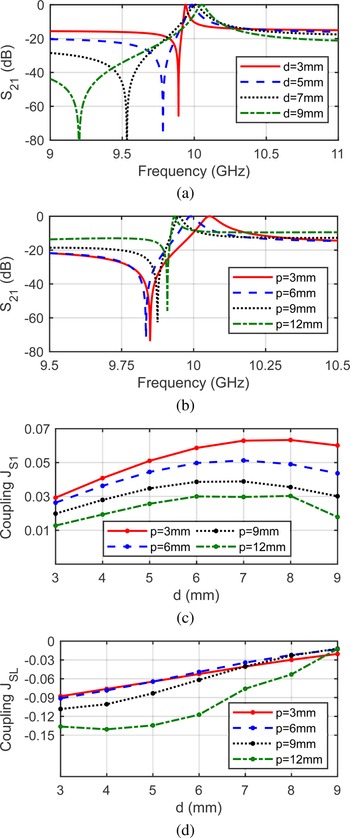
When asymmetric irises are on the same side [see Fig. 4(b)], a TZ below the passband can be realized. As shown in Fig. 5(a), the location of the TZ can easily be varied by varying dimension d of each iris. Some fine adjustment is also achievable by changing distance p of each iris from the ridge [Fig. 5(b)]. In this case, all couplings are non-zero J S1 ≠ 0, J 1L ≠ 0, and J SL ≠ 0. Fig. 5(c) shows the source to resonator coupling versus d and p. Fig. 5(d) gives the plot of source to load coupling versus d and p. Note that J S1 is positive and J SL is negative for the same side irises.
Transverse rectangular ridge resonator with asymmetric irises on the same side. (a) S 21 for different values of d, (b) S 21 for different values of p, (c) J S1 versus variations in d and p, and (d) J SL versus variations in d and p.

It is worth mentioning that Fig. 5 shows the singlet for which d and p of input and output irises are equal and thus J S1=J 1L, which is not necessarily required by the structure.
Transverse rectangular ridge resonator with asymmetric irises on the opposite sides
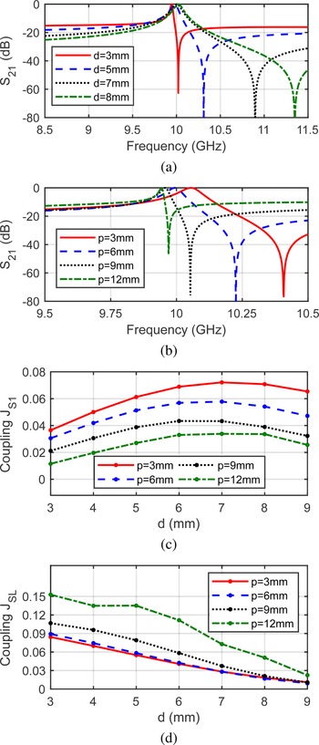
For asymmetric irises located on the opposite sides [see Fig. 4(c)], a TZ above the passband can be realized. Location of the TZ can be changed by varying dimension d and/or p, as shown in Figs 6(a) and 6(b). All coupling coefficients namely J S1, J SL, and J 1L are non-zero in this case. As shown in Figs 6(c) and 6(d), both J S1 and J SL are positive thus leading to a TZ above the passband. Note that Fig. 6 shows the singlet for which d and p of input and output irises are equal and thus J S1=J 1L, which is not necessarily required by the structure.
Transverse rectangular ridge resonator with asymmetric irises on the opposite sides. (a) S 21 for different values of d, (b) S 21 for different values of p, (c) J S1 versus variations in d and p, and (d) J SL versus variations in d and p.

It is worth mentioning, that for cases discussed in subsections ‘Transverse rectangular ridge resonator with asymmetric irises on the same side’ and ‘Transverse rectangular ridge resonator with asymmetric irises on the opposite sides’, dimensions d and p, of each input and output irises can be adjusted independent of each other. This means J S1 and J 1L do not necessarily have to be the same, leading to more flexibility in realization of desired filter responses.
Third-order pseudoelliptic filter with one TZ
A third-order filter with one TZ in the lower stopband is designed. Lower stopband TZ is realized using the singlet with the same side irises [see Fig. 4(b)]. The coupling and routing diagram for this filter is shown in Fig. 7. The coupling matrix is of the form

Coupling and routing diagram for the third-order filter with one TZ.

The coupling matrix for the required filter response is synthesized using optimization-based technique [Reference Amari, Rosenberg and Bornemann27]. The coupling matrix response is shown in Fig. 8. The synthesized coupling matrix is given below:

To design the filter from this coupling matrix, an equivalent circuit shown in Fig. 9 has been synthesized. The equivalent circuit is comprised of input and output couplings (K S1 and K 3L), waveguide sections (WG 1 and WG 3 of lengths ℓ1 and ℓ3, respectively) and singlet (S2). Using the basic microwave network theory [Reference Pozar28], each block of the equivalent circuit can be represented as ABCD matrix. The resulting ABCD matrix of the complete filter is obtained by multiplying individual matrices and is given as:

where ABCD matrices for input and output couplings and waveguide sections may be given as below [Reference Pozar28, Reference Hong29]:


where β is the phase constant of the TE10 mode in the rectangular waveguide.
Comparison of coupling matrix, circuit, FEST3D, and HFSS responses for the third-order filter.

Equivalent circuit for third-order filter with one TZ.

The singlet ABCD matrix is obtained from scattering parameters by using standard conversion tables [Reference Pozar28]. Singlet S-parameters can be obtained from its coupling matrix of (2), using equations from [Reference Amari, Rosenberg and Bornemann27].
To synthesize the equivalent circuit of Fig. 9, optimization-based methodology [Reference Amari, Rosenberg and Bornemann27] is utilized. The design parameters to be obtained through optimization are given as the vector below:

The cost function utilized is given in (7), where the S-parameters for each iteration and each frequency point are obtained using (5) and converting the ABCD to S-parameters.

where S 11req = 10−RL/20. f pi and f zj are the required poles and TZs frequencies, respectively. w pi and w zj are the weights for poles and zeros, respectively, which may be adjusted to give more importance to certain terms in the cost function. w pi = 1 and w zj = 100 have been used for this third-order filter design. RL is the required return loss in the passband of the filter. f 1 and f 2 are the frequency points at the edges of the passband. m is the number of TZs and n is the number of poles. For this filter, f 1 = 10.1 GHz, f 2 = 10.4 GHz, RL = 20 dB, n = 3, and m = 1.
The synthesized equivalent circuit parameters are shown in Table 1.
Synthesized equivalent circuit parameter values for the designed third-order filter.

The frequency response of this synthesized equivalent circuit has been plotted in Fig. 8, and it compares well to the coupling matrix response.
Using the synthesized equivalent circuit [see Table 1], the physical dimensions of the filter can be determined. Using K S1 and K 3L, the iris width of the input and output irises, respectively, can be determined using the well-known inductive iris-based filter design procedure [Reference Cameron, Mansour and Kudsia30]. The physical lengths for the two waveguide sections are already synthesized and are given in Table 1. For the singlet S2, full-wave electromagnetic simulations have been used to match the S-parameter response of the synthesized singlet coupling matrix, to the actual structure of Fig. 4(b). The comparison of circuit response and the simulation response is shown in Fig. 10, which shows the two responses are almost similar. The reference planes at the input and output of the simulated singlet structure are adjusted, to achieve phase response almost similar to that of the singlet coupling matrix phase response.
Comparison of circuit and simulation responses of the singlet S2.

The resulting dimensions are then utilized to draw the structures in FEST3D and HFSS. Some optimizations are essential in these three-dimenstional electromagnetic simulation tools, since the circuit model does not cater for all the higher-order mode effects. Optimizations are first carried out in FEST3D and then finalized in HFSS. The resulting responses are shown in Fig. 8, which indicate that FEST3D and HFSS responses are a good match to the coupling matrix and circuit responses.
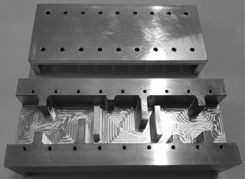
The designed third-order filter is manufactured using CNC milling of aluminum blocks. Photograph of manufactured prototype is shown in Fig. 11.
Manufactured prototype of the third-order filter.

The measurements are carried out on a vector network analyzer. The measured results along with simulated response are shown in Fig. 12. These results indicate a good agreement of the measured S-parameters to the simulated response. Detailed view of the passband insertion loss is shown in the inset of Fig. 12, which indicates the measured insertion loss of 0.28 dB at the center frequency of 10.25 GHz, instead of the simulated value of 0.1 dB. Measured 3 dB bandwidth is 483.8 MHz in contrast to the simulated bandwidth of 489 MHz.
Comparison of measured and HFSS responses of the third-order filter.

Fig. 13 shows the comparison of measured and simulated spurious responses. It can be seen that the upper stopband extends up to 14.65 GHz while no spurious response is observed in the lower stopband.
Comparison of measured and FEST3D broadband responses of the third-order filter.

Fifth-order pseudoelliptic filter with two TZs
A fifth-order pseudoelliptic filter with two TZs above the passband is designed by using two singlets and three half-wave waveguide sections. The singlets utilized make use of the opposite side irises as shown in Fig. 4(c). The coupling and routing diagram for this filter is shown in Fig. 14.
Coupling and routing diagram for the fifth-order filter with two TZs.

The filter can be represented by a 7 × 7 coupling matrix of the form shown below:

This coupling matrix is synthesized using the same method as explained in Section ‘Third-order pseudoelliptic filter with one TZ’, and is given below: M =

The frequency response of the coupling matrix of (9) is shown in Fig. 15. To design this filter, the equivalent circuit of Fig. 16 is utilized. The design procedure makes use of optimization-based strategy and is similar to the one described in Section ‘Third-order pseudoelliptic filter with one TZ’. Each block of the equivalent circuit is represented by its ABCD matrix. The synthesized parameters of the equivalent circuit of Fig. 16 are shown in Table 2.
Comparison of coupling matrix, circuit, FEST3D, and HFSS responses for the fifth-order filter.

Equivalent circuit for the fifth-order filter with two TZs.

Synthesized equivalent circuit parameter values for the designed fifth-order filter.

For each singlet S2 and S4, the frequency response of the circuit [see Table 2] is matched using HFSS. The S-parameter response comparison between circuit and full-wave simulation for each singlet is shown in Fig. 17. The simulated response matches the circuit response for each singlet reasonably well.
Comparison of circuit and simulation responses of the singlets.

Using the same procedure as in Section ‘Third-order pseudoelliptic filter with one TZ’, the resulting dimensions are realized in FEST3D and HFSS for the fifth-order filter. The results of simulations are shown in Fig. 15, which shows good consistency with the coupling matrix and circuit responses. The filter is manufactured and is shown in Fig. 18.
Manufactured prototype of the fifth-order filter.

The measured results for this fifth-order waveguide filter are shown in Fig. 19, which also compares the measured S-parameter response with the HFSS simulated response. The measured S 21 match well with the simulated response. The measured S 11 response indicates that the return loss is deteriorated partially in the passband, which is attributed to machining tolerances.
Comparison of measured and HFSS responses of the fifth-order filter.

To understand the cause for this deterioration in return loss, tolerance analysis is carried out using FEST3D. For each iteration, random error with a Gaussian distribution is added to all filter dimensions, except for the dimensions a and b of the rectangular waveguide. In FEST3D, 50 iterations are performed with the standard deviation of 12.5 μm. The results are shown in Fig. 20. It is observed that the return loss is more sensitive to manufacturing errors while the locations of TZs are less influenced by these errors.
Tolerance analysis of the fifth-order filter.

The inset of Fig. 19 shows the close-up view of the in-band insertion loss. Measured insertion loss is 0.475 dB at 10.175 GHz, instead of the simulated value of 0.24 dB. Measured insertion loss is 0.862 dB at the center frequency of 10.25 GHz, instead of the simulated value of 0.25 dB. The increase in insertion loss at the center frequency is because of the deteriorated return loss at this frequency, which can be estimated using the S-parameters unitary condition for a lossless network [Reference Pozar28] that implies |S 11|2 + |S 21|2 = 1. Thus the measured dissipation loss at 10.25 GHz is 0.45 dB. Using this measured dissipation loss, unloaded quality factor of a waveguide section is estimated as $Q_u^{WG} = 3680$ and that of a ridge resonator as $Q_u^{ridge} = 1363$
 . Measured 3 dB bandwidth is 343.4 MHz in contrast to the simulated bandwidth of 353.3 MHz.
The comparison of measured and simulated spurious responses is shown in Fig. 21, which indicates that the upper stopband extends up till 14.6 GHz while no spurious response is observed in the lower stopband.
Comparison of measured and FEST3D broadband responses of the fifth-order filter.

Conclusion
A new singlet structure for the implementation of waveguide pseudoelliptic filters, using asymmetric iris coupled transverse rectangular ridge resonator has been proposed in this work. This singlet makes use of a rectangular ridge that is fixed at the center of the waveguide and is always tranverse to the waveguide axis, thus making the structure easier to design and manufacture. The ridge is excited by asymmetric irises, whose dimensions are adjusted to achieve the required location of TZs. It has been shown that by proper placement of asymmetric irises relative to each other, a TZ either below or above the passband can be realized.
The proposed singlets along with half-wave waveguide sections have been used to design and manufacture a third-order waveguide filter with one TZ in the lower stopband and a fifth-order waveguide filter with two TZs in the upper stopband. These filters are manufactured by CNC milling of aluminum blocks and are measured using a vector network analyzer. The measured results are compared to simulated responses, thus validating the proposed singlet structure and the design methodology.
 Muhammad Anis Chaudhary received the B.E. and M.S. degrees in Electrical Engineering from the National University of Sciences and Technology (NUST), Pakistan in 2003 and 2010, respectively. He is currently pursuing his PhD degree in Electrical Engineering from the Capital University of Science and Technology (CUST), Islamabad, Pakistan. His research interests include microwave filters and passive structures.
 Muhammad Mansoor Ahmed completed the PhD degree in Microelectronics from the University of Cambridge, UK, in 1995, and joined academia where he worked at different positions including Professor; Chairman; Dean, and Executive Vice President. He is currently working as a Vice Chancellor Capital University of Science and Technology (CUST), Islamabad. Dr Ahmed research interests are in Microelectronics, Microwave and RF Engineering and he has supervised numerous MS and PhD research projects. He authored over 100 research papers in the field of microelectronics. Dr Ahmed is a fellow of the Institution of Engineering and Technology (IET), UK; a Chartered Engineer (CEng) from the UK Engineering Council and holds the title of European Engineer (Eur Ing) from the European Federation of National Engineering Association (FEANI), Brussels. He is a life member of PEC (Pak); EDS & MTTS (USA).