I. INTRODUCTION
Zirconium (Zr) and Zr alloys show many desirable physicochemical properties, namely, small thermal neutron absorption cross-section, good corrosion resistance, excellent anti-irradiation, and so on. These materials have been widely used in the nuclear industry and in applications that require high chemical corrosion resistance. Recently, Zr alloys are appreciated by researchers.Reference Zhilyaev, Sabirov, González-Doncel, Molina-Aldareguía, Srinivasarao and Pérez-Prado1–Reference Han, Zhang, Lu and Zhang4 To develop Zr alloys as structural materials, Zr-based bulk metallic glasses with high strength and hardness have been intensively researched.Reference Li, Zhang, Dong, Qiang, Makino, Fukuhara and Inoue5,Reference Wang, Yang, Jiang, Saksl, Franz, Fecht, Liu and Xian6 However, the disadvantages such as fragility, small size, expensive, and more singularities limit their application. Recently, Liang et al.Reference Liang, Ma, Jing, Zhang and Liu7–Reference Liang, Ma, Jing and Liu9 supplied several high-strength ZrTi-based alloys with two ductile phases. However, the plastic deformation mechanisms of those high-strength Zr alloys have been rarely reported.
Plastic deformation mechanisms of metals and alloys are greatly dependent on lattice structure, grain size, deformation temperature, strain rate, stacking fault energy, and so on.Reference Zhu, Liao and Wu10,Reference Liao, Zhao, Srinivasan, Zhu, Valiev and Gunderou11 However, the lattice structure has one of the most important effects on deformation mechanism. Metals and alloys with face-centered cubic (fcc) and body-centered cubic (bcc) lattices have enough independent slip systems for free deformation. Thus, coarse-grained metals and/or alloys with fcc or bcc lattice structure, such as copper, only deform by dislocation slip but not by twinReference Hansen and Ralph12,Reference Johari and Thomas13 except at very high strain rates and/or low temperatures.Reference Liao, Zhao, Zhu, Valiev and Gunderov14,Reference Wu, Liao, Srinivasan, Zhou, Lavernia, Valiev and Zhu15 Kaibyshev et al.Reference Kaibyshev, Musin, Avtokratova and Motohashi16 showed that no deformation twin could be found in the transmission electron microscopy (TEM) microstructure of the 5083 Al strained up to a true strain of 2.3. Ivanisenko et al.Reference Ivanisenko, Kurmanaeva, Weissmueller, Yang, Markmann, Rösner, Scherer and Fecht17 investigated the deformation mechanism of metal palladium and also showed that the operative deformation mechanism of palladium in common grain size was only dislocation slip. Resulting from only three independent slip systems in metals and/or alloys with hexagonal close-packed (hcp) structure, such as zirconium, titanium, magnesium and their alloys, it is insufficient to adapt to a consecutive plastic strain according to the von Mises criterion. In addition to the dislocation slip, deformation twin plays an important role in these metals and/or alloys. Nemat-Nasser et al.Reference Nemat-Nasser, Guo and Cheng18 investigated the deformation mechanism of cp-Ti deformed at various temperatures and showed that deformation twins in cp-Ti can present even at temperatures exceeding 800 K. StanfordReference Stanford, Sotoudeh and Bate19 also observed the deformation twins when researched the deformation mechanism of magnesium alloy AZ31.
Metallic Zr has two crystal structures, namely, hcp (α-phase) and bcc (β-phase) structures. α-Zr transforms into β-Zr when the temperature is increased to the transition temperature that is greatly affected by addition of an alloying element.Reference Dargusch, Bermingham, McDonald and StJohn20 As enough β-stabilizer is added, the β-phase can be retained at room temperature and pressure. Based on the crystal structure at room temperature and pressure, Zr(Ti)-based alloys can be classified into three basic types, α, α + β, and β types. According to the above presentation about deformation mechanism, nearly all of the reports are targeted to the deformation mechanism of single-phase alloys or two-phase alloys with a fine, hard, and brittle second phase. The aim of this paper is to study the deformation mechanism of a typical high-strength Zr(Ti)-based alloy with α and β two ductile phases.
II. EXPERIMENTAL PROCESS
Sponge Zr (Zr + Hf ≥ 99.5 wt.%), sponge Ti (99.7 wt.%), industrially pure Al (99.5 wt.%), and V (99.9 wt.%) were used to prepare the Zr–62Ti–5Al–3V (wt.%) alloy. The preparation procedures contained smelting, breakdown, and forging, and the details are available in Ref. Reference Hsu, Wu, Hsu, Sung and Ho2. The heat treatments were performed in a SK-G06143-type tubular vacuum heat-treatment furnace with protective argon atmosphere. The samples with 10 × 10 × 70 mm were held at 850 °C for 30 min and cooled at 0.35 °C/min.
X-ray diffraction (XRD), scanning electron microscopy (SEM), and TEM were used to test and/or analyze the phase structure and composition, surface morphologies, and microstructures, respectively. A differential scanning calorimeter (DSC) was used to test the phase transition temperatures. SEM specimens were prepared by a standard method of metallographic specimen and electropolishing technology. The electrolyte is the solution of 10% (v/v) perchloric acid and 90% (v/v) glacial acetic acid. Electrolysis voltage is in the range from 12 to 20 V, and the electrolysis time is in the range from 30 s to 2 min. TEM specimens were prepared by twin-jet electrochemical polishing in a solution of 10% perchloric acid and 90% methanol at 13 V and 238 K.
III. RESULTS AND DISCUSSION
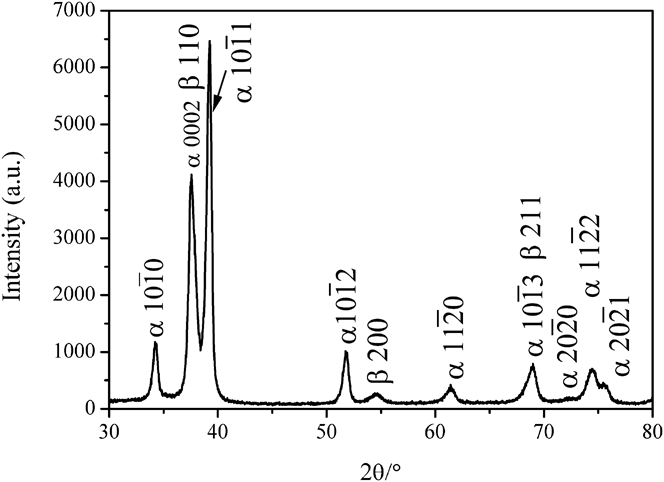
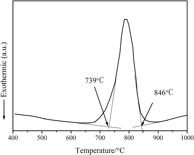
Figure 1 shows the XRD pattern of the examined ZrTiAlV alloy held at 850 °C for 30 min and cooled at 0.35 °C/min. Apart from the main peaks of the α-phase and the obvious peak 2θ ≈ 54° of the β-phase, no other peak can be found. The XRD results show that the heat-treated ZrTiAlV alloy is wholly composed of α and β phases. Although the element Al is a typical α-stabilizer for Zr and Ti, the addition of element V as a typical β-stabilizer can increase the stability of the β-phase in the alloy system. The DSC result (Fig. 2) shows that the α + β to β transition temperature of the examined alloy is about 846 °C much lower than that of TC4 alloy. The β-phase in the studied ZrTiAlV alloy system is stable enough to be retained at room temperature and pressure. Further study of the XRD pattern shows that the lattice constants of the α-phase with hcp structure are 0.29938 nm for a and 0.47832 nm for c, namely the value of axial ratio c/a is 1.5977, and the lattice constant of the β-phase with bcc structure is 0.33538 nm.
XRD pattern of the heat-treated ZrTiAlV alloy.

DSC curve of the examined ZrTiAlV alloy.
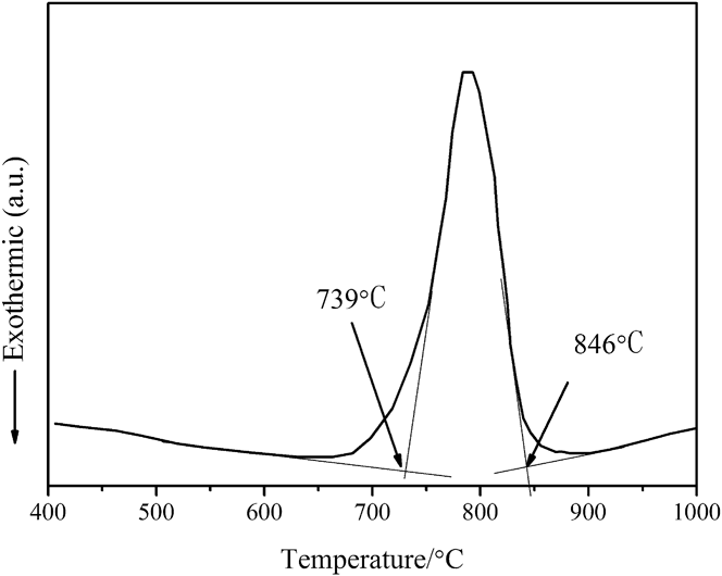
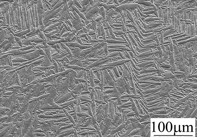
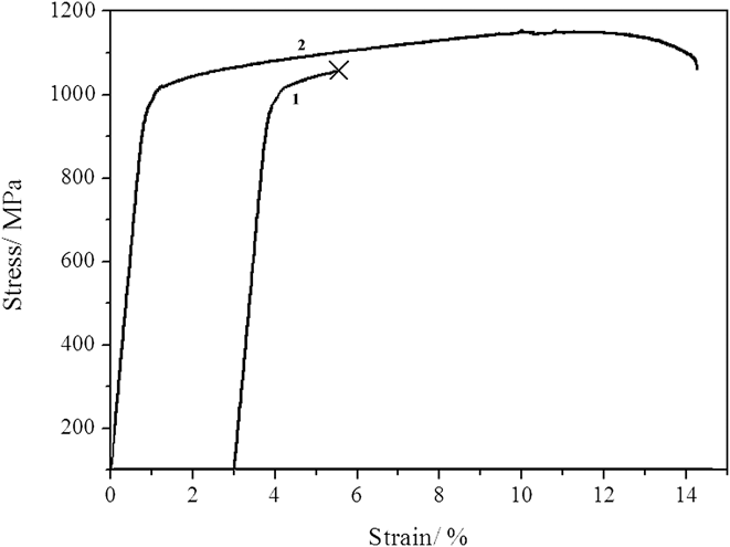
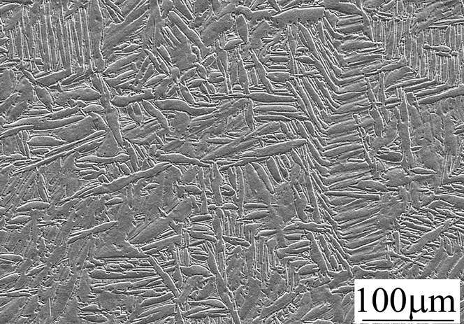
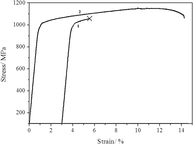
Figure 3 shows the SEM microstructure of the examined ZrTiAlV alloy. The examined ZrTiAlV alloy exhibits a typical basketweave microstructure,Reference Oh, Jeong, Lee and Kim21 which is characterized by the plate second phase in the matrix phase. According to the theory of solid phase transformation, SEM and XRD results, it is easy to know that the plate α-phase is interlaced and the retained β-phase is separated by the interlaced α-phase. Figure 4 shows the stress–strain curves of the examined alloy. The curve 1 in Fig. 4 belongs to the tensile test stopped artificially at strain 2.5%, and curve 2 belongs to the fractured specimen. According to these two stress–strain curves, the yield strength, tensile strength, and elongation are 988 MPa, 1155 MPa, and 13.3%, respectively.
SEM microstructure of the heat-treated ZrTiAlV alloy.
Stress–strain curves of the examined alloy.
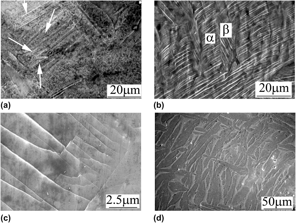
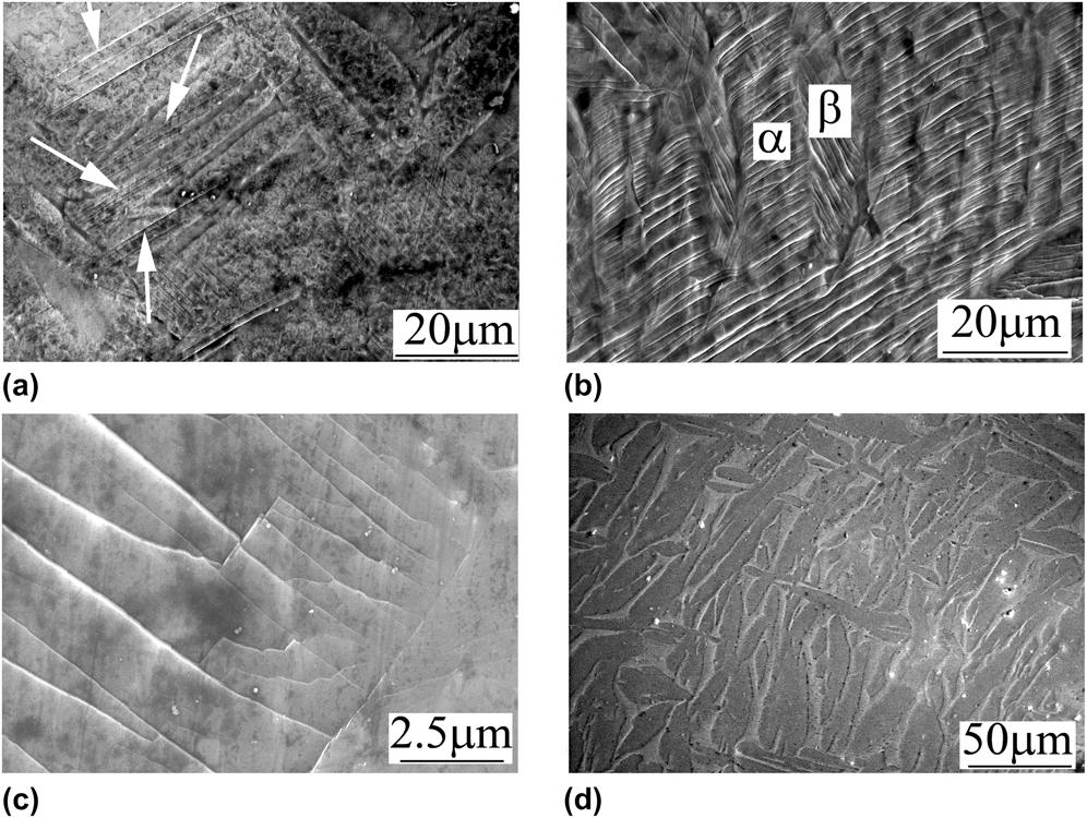
The surface morphologies of the examined alloy after room temperature tensile tests are shown in Fig. 5. Figure 5(a) shows the surface morphology after the tensile test is stopped at ε = 2.5%. A small number of slip bands are observed in the plate α-phase, but not in the β-phase. Thus, the plastic deformation can be inferred to start at the α-phase. The surface morphologies of the fractured specimens [Figs. 5(b) and 5(c)] show a large number of slip bands both in α and β phases, as well as some characters of multisystem slips. The fact that the crystalline orientation does not change while dislocation line slip through grains and some small steps can be observed on deformed surfaces. These steps (slip bands) will disappear after repolishing. Conversely, grains are separated by twin boundaries if the deformation mechanism is twin and crystalline orientations beside twin boundaries are different, so, the deformation twins can still be observed on repolished deformed surfaces. In a word, after repolishing the deformed surface, slip bands will disappear but deformation twins will visualize if any. From what was said above, no deformation twin can be observed in the repolished surface morphology of a fractured specimen in Fig. 5(d). Thus, the deformation mechanism of the examined alloy is only a slip mechanism, and plastic deformation starts at the α-phase.
SEM images of the surface morphology after tensile tests (a) ε = 2.5%, (b) and (c) fracture, and (d) repolishing after fracturing.
TEM images and the corresponding diffraction patterns of slip bands near the tensile fractured surface are shown in Fig. 6. Analysis of TEM images shows that the plastic deformation in the α-phase of examined ZrTiAlV alloy with a basketwave (BW) microstructure is mainly derived from an (0001) basal slip [Fig. 6(a)] as well as a few multisystem slips composed of (0001) basal and  $(10\bar 10)$ prismatic slips [Fig. 6(b)]. The deformation twin is still not observed in the TEM specimen. TEM results further demonstrate that the plastic deformation mechanism of the examined ZrTiAlV alloy with hcp structure and bcc structure two ductile phases is only a slip mechanism. Generally, the plastic deformation capacity of the hcp structure is weaker than that of the bcc structure. However, the slip starts at the α-phase, whose structure is hcp in the examined alloy with two ductile phases. This finding can be attributed to the β-phase encircled by α-phases in the BW microstructure. To ensure the integrality of the specimen during deformation, plastic deformation must first occur at α-phases. Furthermore, the critical resolved shear stresses of dislocation slipping along the basal and prismatic planes in the α-phase are 0.15 and 0.12 GPa, respectively, lower than 0.24 GPa in the β-phase.Reference Cai, Daymond and Holt22 The ductile behavior of an alloy with a hcp structure usually results from the activation of twining deformation modes in addition to conventional slips by dislocations. Previous reportsReference Manero, Gil and Planell23–Reference Mccabe, Proust, Cerreta and Misra26 on the deformation of Zr or Ti alloys also show both slipping and twining deformation modes. However, the twining deformation modes are not activated in the examined ZrTiAlV alloy. Apart from the α-phase, the β-phase is also contained in the examined alloy. The slipping of dislocation in the β-phase is not activated in the early stage of the tensile test. However, the critical resolved shear stress of dislocation slipping in the β-phase is far less than that of the activation of twining deformation modes in the α-phase resulting in the activation of dislocation slipping in the β-phase before twining deformation in the α-phase. The plastic deformation capacity of the β-phase is strong, resulting from the large number of slip systems. Therefore, twining deformation modes in the α-phase are inhibited by the existence of the β-phase. Otherwise, the maximum flow stress in tensile tests is about 1155 MPa, which can only activate the dislocations slipping along the basal and prismatic planes in the α-phase and dislocations slipping in the β-phase, but is not enough for the activation of deformation twins in α-phase, which is hard than the activation of dislocations in β-phase. The TEM analysis also indicates that the slip plane in the α-phase is mainly the (0001) plane in the examined alloy with α and β two ductile phases, different from previous reports,Reference Brenner, Béchade, Castelnau and Bacroix27–Reference Liu29 which show that the slip of dislocation motion in Zr or Ti alloys is mainly along the
 $(10\bar 10)$ prismatic plane. In α-Zr, the lattice parameters of the hcp structure are a = 0.3232 nm and c = 0.5147 nm, giving a c/a ratio of 1.5925. For an ideal hcp lattice, the c/a ratio is 1.633. The increase of the c/a ratio from 1.592 of α-Zr close to 1.633 (ideal c/a ratio) may result in a change of the slip system from the
 $(10\bar 10)$ prismatic slip to the (0001) basal slip. The incorporation of substitutional atoms with smaller atomic radii than Zr, e.g., Al and V, slightly increases the c/a ratio of α-Zr. The c/a ratio of the examined alloy is 1.5977 closer to 1.633 than 1.592, resulting in the lower critical resolved shear stress of the basal slip than that of the prismatic slip. Thus, the basal slip is easy to activate than the prismatic slip.
TEM images near the fractured area and corresponding fraction patterns in the top right-hand corner: (a) (0001) basal slip and (b) multisystem slips: (0001) basal slip and  $(10\bar 10)$ prismatic slip.
IV. CONCLUSIONS
The Zr–62Ti–5Al–3V (wt.%) alloy was prepared in this paper. To obtain two ductile phases, the heat treatment held at 850 °C for 30 min and cooling at 0.35 °C/min was performed on that alloy. The XRD and microstructural results indicate that the heat-treated alloy is composed of the hcp structure α-phase and the bcc structure β-phase, and its microstructure shows the typical character of the basketweave microstructure. The deformation mechanism of the examined alloy with hcp and bcc two structure phases is studied in this paper, and the main conclusions are as follows:
(1) The plastic deformation in the examined ZrTiAlV alloy with α and β two ductile phases starts at the α-phase first, and then at the β-phase.
(2) The plastic deformation mechanism of the examined alloy with hcp and bcc structure phases is only a dislocation slip mechanism. No deformation twin was found near the fractured area of the examined alloy.
(3) The main slip plane in the α-phase with hcp structure is the (0001) plane as well as a few slips along the
 $(10\bar 10)$ plane.

ACKNOWLEDGMENTS
This work was supported by the SKPBRC (Grant No. 2013CB733000/2010CB731600), NSFC (Grant No. 51121061/51171160/51171163), and DFME of China (Grant No. 20101333110004).