I. INTRODUCTION
Over the past few years, a remarkable development in indoor and outdoor wireless activities enhances the multiple input multiple output (MIMO) antenna technology. Most of the wireless work on MIMO antenna systems was reported and investigated for wireless local area network (WLAN)/worldwide interoperability for microwave access (WiMAX)/long term evolution (LTE) and other required applications. MIMO technology is a good candidate in non-line of sight (NLOS) communication to provide better quality of services. The idea of MIMO was started with the capacity theorem [Reference Shannon1] and its application on wireless communication with pulse amplitude modulation signals [Reference Kaye and George2], multivariate analysis over the Gaussian channel with memory [Reference Branderburg and Wyner3], multi-channel digital transmission systems [Reference Van Etten4, Reference Van Etten5], and directional digital transmission and reception using beam-forming signal-processing applications [Reference Winters6, Reference Salz7]. The idea of using an array at the base station to improve channel characteristics for transmission and reception with space division multiple access invoked in minds of Richard Roy and Bjorn Ottersten [Reference Roy and Bjorn8]. The concept of gain enhancement using spatial multiplexing (SM) techniques in MIMO was proposed by Arogyaswami Paulraj and Thomas Kailath. They showed the concept of increasing data rate by dividing, transmitting, and receiving high-data rate signals into low-data rate signals [Reference Paulraj and Kailath9]. A new concept of link through improvement of MIMO by using co-located antennas at the transmitter was carried out by Greg Rayleigh, Gerard J. Foschini, and Emre Telatar. The Bell laboratory first demonstrated a practically realizable prototype of SM to enhance the performance of MIMO communication systems [Reference Rayleigh and Cioffi10–Reference Telatar12].
The need of MIMO arises due to the drawbacks of single-input single-output (SISO) system established at the transmitter and receiver. The SISO places impossible bandwidth demands on the gigabit wireless system. Therefore, gigabit per second wireless links in NLOS communication networks using SISO are in general not feasible due to signal-to-noise ratio limits, average signal to interference with noise ratio limits, high-power/bandwidth requirements, and due to range reduction in practical receivers [Reference Paulraj and Kailath9]. MIMO can be a integral part of present key technologies for the performance enhancement, i.e. gain, capacity, data rate, and efficiency, etc.
However, the compact and portable devices place a lower and upper bound on the space limits for the commercial/experimental wireless communication products. The close proximity of radiating elements in MIMO has compactness but at the cost of performance degradation. Another degradation is due to the shared ground effects. Such degrading effect is jointly known as a mutual coupling, which severely affects the diversity behavior and radiation characteristics. Various diversity techniques like space diversity, polarization diversity, and pattern diversity are having their merits and demerits to control the degrading effects of mutual coupling. Other techniques are also required along with diversity techniques to control the mutual coupling between radiators. The paper is discussed in three sections. Section II explains different diversity and mutual coupling reduction techniques with their merits and demerits. Section III shows the second aspect of Section II utilized for the miniaturization of MIMO antennas.
II. DIVERSITY AND MUTUAL COUPLING REDUCTION TECHNIQUES
An envelope correlation coefficient (ECC) is evaluated for the uncorrelated channels to find whether the channel is good, bad, or good enough. In real propagation world, even in line of site communication, finding a truly uncorrelated channel is impossible. Therefore, ECC is used for the measurement of such conditions. The S parameter approach as well as far-field analysis are considered to find the value of ECC. The effect of mutual coupling between any of the two ports of MIMO can be seen in terms of two scattering parameters, i.e. S 12 and S 21. However, ECC involves all the scattering parameters of the designed MIMO to show their effects on the correlation coefficient (ρ). Lower the value of ECC means less correlation between antenna elements, while higher values of it shows the negative impact. For the good diversity behavior, the value of ECC must be <0.5 for mobile applications. The values of ECC [Reference Han and Choi34] may be obtained using the formula given in equation (1). Here the values of i = 1 to n, j = 1 to n, and N = number of radiating elements.
 $$\left \vert {\rho _e (i,j,N)} \right \vert = \displaystyle{{\left \vert {\sum\nolimits_{n = 1}^N {S_{i,n}^* S_{n,j}}} \right \vert} \over {\sqrt {\left \vert {\prod\nolimits_{k( = i,j)} {\left[ {1 - \sum\nolimits_{n = 1}^N {S_{i,n}^* S_{n,k}}} \right]}} \right \vert}}}. $$
The ECC can be obtained using the far-field characteristics [Reference Yang, Kim and Kim104] of the radiating elements. Let the
 $\bar F_1 (\theta, \phi )$
and
 $\bar F_2 (\theta, \phi )$
are the field patterns of two radiating elements with respect to the θ and ϕ components, then ECC can be written in equation (2):
 $$\rho _e = \displaystyle{{\left \vert {\int\!\!\!\int_{4\pi} \left[ {\bar F_1 (\theta, \phi ) \bullet \bar F_2 (\theta, \phi )} \right]} \right \vert ^2} \over {\int\!\!\!\int_{4\pi} \left \vert {\bar F_1 (\theta, \phi )} \right \vert ^2 d\Omega \int\!\!\!\int_{4\pi} \left \vert {\bar F_2 (\theta, \phi )} \right \vert ^2 d\Omega}}, $$
where
 $ \bullet $
is the Hermitian product operator and Ω is the solid angle.
The another way of utilizing the far-field characteristics to get ECC [Reference Ghosh, Tran and Le Ngoc39, Reference Singh, Pandey, Bharti and Meshram73], is given by equation (3):
 $$\left \vert {\rho _e} \right \vert ^2 = 1 - \displaystyle{{\eta _{max}} \over {\eta _1 \eta _2}}, $$
where η max is the maximum efficiency, η 1 is the total efficiency of radiating element 1, and η 2 is the total efficiency of radiating element 2. The η max is the function of power distribution of the radiating elements. Therefore, the ECC is dependent on the efficiency and power distribution of the radiating elements.
Similarly, the diversity gain (DG) is also dependent on correlation (mutual coupling) [Reference Singh, Pandey, Bharti and Meshram73], which is obtained in terms of maximum theoretical DG (10 dB) and ρ by using equation (4). Lower the value of correlation, higher will be the DG and vice versa.
 $$G_{DG} = 10 \times \sqrt {1 - \left \vert \rho \right \vert ^2}. $$
Similarly, the total active reflection coefficient (TARC) is also one of the parameter, which is dependent on the returnloss and correlation. The TARC involves random signals and their phase angles for diagonal/adjacent ports to compute the radiation performance of designed MIMO. It also investigates the actual behavior of the scattering parameters like S 12 (between ports 1 and 2), S 13 (between ports 1 and 3), and S 14 (between ports 1 and 4) in case of four-port MIMO with required phase angle(s) between ports for better performance of design.
Let a i is excitation vector, and b i is scattering vector. The ratio of b and a for a particular port results in return-loss/isolation parameter (S ii or S ij ). The formula of TARC [Reference Sharawi, Khan, Numan and Aloi101] can be written in equation (5).
 $$\Gamma _a^t = \displaystyle{{\sqrt {\sum\nolimits_{i = 1}^N {\left \vert {b_i} \right \vert ^2}}} \over {\sqrt {\sum\nolimits_{i = 1}^N {\left \vert {a_i} \right \vert ^2}}}}. $$
The complete formula of TARC for any of the two adjacent/diagonal radiating ports can be shown in equation (6) as:
 $$\Gamma _a^t = \displaystyle{{\sqrt {\left \vert {(S_{ii} + S_{ij} *e^{jq} )} \right \vert ^2 + \left \vert {(S_{ji} + S_{jj} *e^{jq} )} \right \vert ^2}} \over {\sqrt N}}, $$
where θ is the phase angle between any of the two adjacent/diagonal ports.
Similarly, the performance of the MIMO is also characterized by the channel capacity [Reference Singh, Pandey, Bharti and Meshram73], which is also dependent on the scattering parameters (i.e. returnloss and ρ) of the designed MIMO antenna. Let us consider a multipath transmission channel having multiple transmitting antennas (N t ) on one side and receiving antennas (N r ) on the other side. The formula of channel capacity may be written as shown in equation (7):
 $$C = \mathop {\log} \nolimits_2 \left( {I_{Nr} + \displaystyle{P \over {NN_t}} HH^*} \right),$$
where P is the signal power, N is the noise power (capacity of SISO is
 $C = \mathop {\log} \nolimits_2 (1 + (P/N))$
), * denotes a complex conjugate transpose operation, H is the channel matrix and its transpose is H*. The response of H is completely dependent on the correlation/mutual coupling between radiators, which is the function of channel parameters of the propagation environment, i.e. delay, gain, noise, interference, etc. The appropriate knowledge of channel and its parameters enable to find out the value of H. The channel matrix for two-port MIMO is shown in equation (8):
 $$H = \left[ {\matrix{ {h_{11}} & {h_{12}} \cr {h_{21}} & {h_{22}} \cr}} \right].$$
Similarly, in NLOS conditions, the directive gain is insufficient to deliver accuracy of results. Therefore, mean effective gain (MEG) is used in such conditions and is measured in an anechoic chamber for the far-field characterization. The MEG [Reference Sharawi, Khan, Numan and Aloi101] includes efficiency and power patterns of the MIMO antenna. Let the cross-polarization ratio of the incident field is denoted by XPR. The probability distribution functions (pdf) of the incident wave are p θj and p ϕj for θ and ϕ components. The power gains of 2 × 2 MIMO antenna elements are G θj and G ϕj . The value of j is 1–4 for four elements. The formula of MEG in two-dimensional plane is given by equation (9).
 $$\eqalign{MEG_j & = \oint \left( {\displaystyle{{XPR} \over {1 + XPR}}P_{\theta j} (\Omega )G_{\theta j} (\Omega )} \right. \cr & + \left. {\displaystyle{1 \over {1 + XPR}}P_{\phi j} (\Omega )G_{\phi j} (\Omega )} \right).}$$
The above equation of MEG can also be written as shown in equation (10).
 $$\eqalign{MEG_j & = \displaystyle{1 \over {2\pi}} \int_0^{2\pi} \left[ {\displaystyle{{XPR} \over {1 + XPR}}G_{\theta j} \left( {\displaystyle{\pi \over 2},\phi} \right)} \right. \cr & + \left. {\displaystyle{1 \over {1 + XPR}}G_{\phi j} \left( {\displaystyle{\pi \over 2},\phi} \right)} \right]d\phi.}$$
The maximum value of MEG with 100% efficiency is −3 dB. However, the efficiency also depends on the mutual coupling. For MIMO, each element should have equal value of MEG to get optimum diversity performance. The value of XPR(XPD) = 0 dB for outdoor uniform environment, and XPR(XPD) = 6 dB for indoor uniform environment. As MEG includes the effect of G θj and G ϕj , which are the functions of the mutual coupling between radiators.
A thorough literature survey of diversity and mutual coupling reduction techniques are explored in details in literature.
A) Space diversity
The space diversity is the first kind of isolation enhancement technique between the closely packed radiating elements. The space variation is the key of this approach to achieve de-correlation or low mutual coupling between radiators. This is equally valid for all types of MIMO antenna structures such as monopole-, dipole-, conventional-shaped, planar inverted frequency antenna (PIFA), and fractal geometries, etc [Reference Azremi13]. A reasonable distance between the radiating elements ensures the proper operation of the design and produces the desired performance parameters along with the limited coupling current, responsible for mutual coupling [Reference Vaughan and Anderson14]. The close spacing between radiators is the major source of coupling (radiation emission) and common conductor (ground) emission [Reference Paul15]. The analysis of transfer function of a correlation coefficient revels the behavior of a designed MIMO. The separation, placement, and the orientation of radiating elements with the partial/stepped/full ground play a major role in deciding the value of mutual coupling [Reference Manteuffel16].
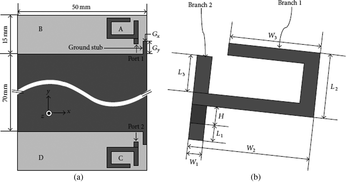
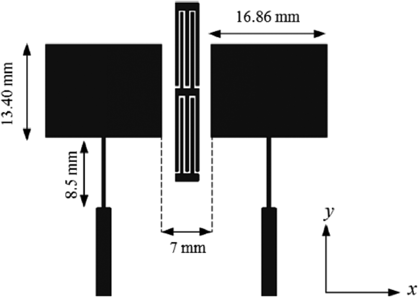
The spacing constraint must be there to ensure the compactness of the overall size along with the proper treatment of degrading factors [Reference Lau and Ying17]. A space orientation (digonally placement, face to face, 180° face shifted, etc.) is also the prime requirement for controlling mutual coupling and enhancing diversity parameters of a designed MIMO [Reference Karaboikis, Papamichael, Tsachtsiris, Soras and Makios18, Reference Lin and Liu19]. The space orientation has one of the important characteristics that it changes the direction of current flow, which in turn controls the correlation. The narrow/wide-band MIMO antennas were designed for WLAN/WiMAX/LTE applications with reasonable separation (space diversity) and space orientation for desired band of operations as shown in Fig. 1 [Reference Jeong, Choi, Lee and Kim20, Reference Khan and Sharawi21]. The value of isolation is more than 10 dB in this approach.
Space diversity MIMO antenna © [Reference Jeong, Choi, Lee and Kim20].

B) Polarization diversity
The space diversity technique at the base station is having a lot of space for implantation of MIMO antennas due to no space constraint there. However, at the mobile station, space constraint is required due to portability and mobility of devices. The polarization diversity on the other hand is simple and results in compactness of the overall MIMO antenna system. All the antennas are placed as a diversity branches, i.e. vertically and horizontally positioned [Reference Lee and Yeh22, Reference Malviya, Panigrahi and Kartikeyan23]. This in turn enhances capacity also due to the improvement in link quality. The placement of radiators and ground planes in 90° results in lower installation costs and better performance than space diversity. It can be equally incorporated with similar/desimilar or mixed radiating structures. Designers take the benefit of dielectric slabs placed between the radiators for the compactness of the overall design with polarization diversity. Experimentally, this verifies the improved performance of MIMO antennas in terms of compactness, gain, isolation (mutual coupling), and bandwidth [Reference Yeap, Chen, Dupuy, Chiau and Parini24].
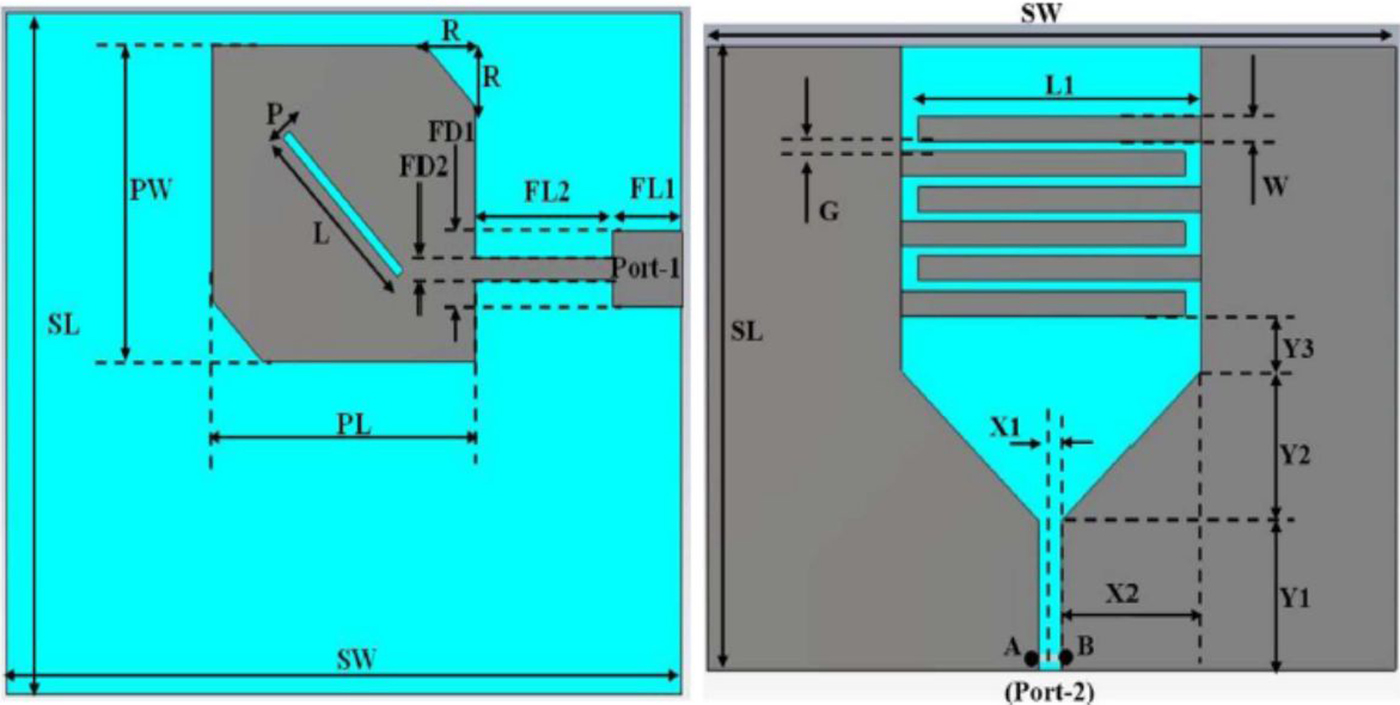
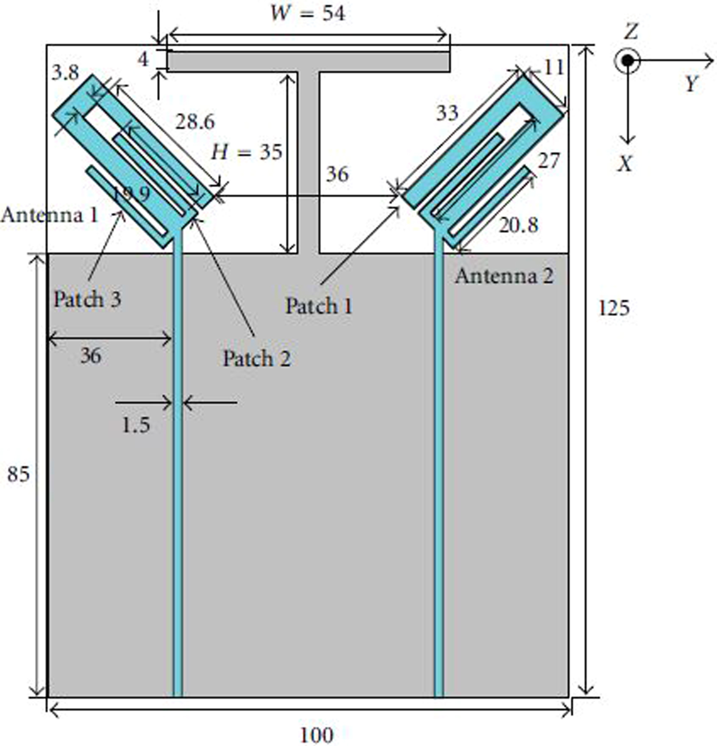
Many times, feed probes are designed to ensure polarization diversity [Reference Garcia, Lindmark and Orlenius25]. The link reliability along with the low mutual coupling can be achieved by the joint incorporation of polarization and pattern diversities in a MIMO antenna [Reference Oh and Sarabandi26, Reference Zhang, Wang, Yu and Huang27]. The combination ensures enhanced diversity properties. A design related with this is shown in Fig. 2 [Reference Malik, Patnaik and Kartikeyan28, Reference Liao, Hsieh, Dai and Hsiao29].
MIMO antenna with pattern and polarization diversities © [Reference Malik, Patnaik and Kartikeyan28].

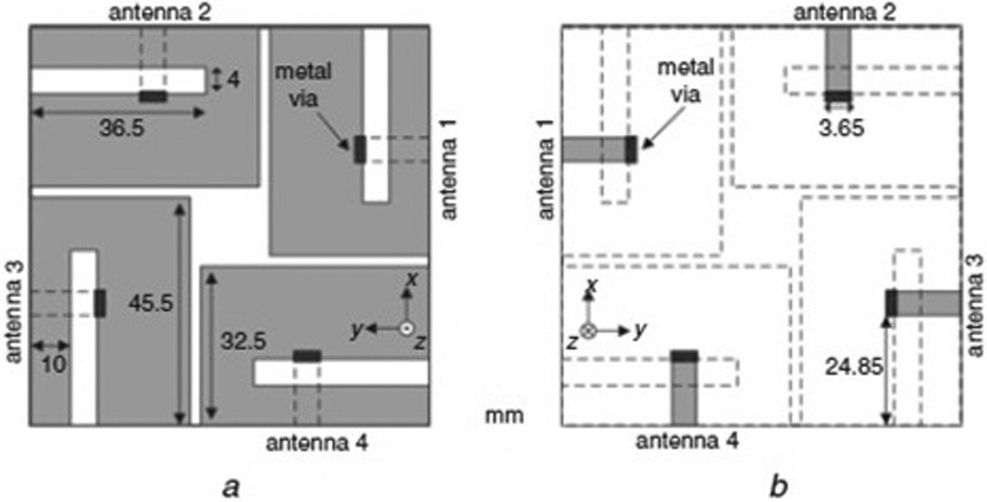
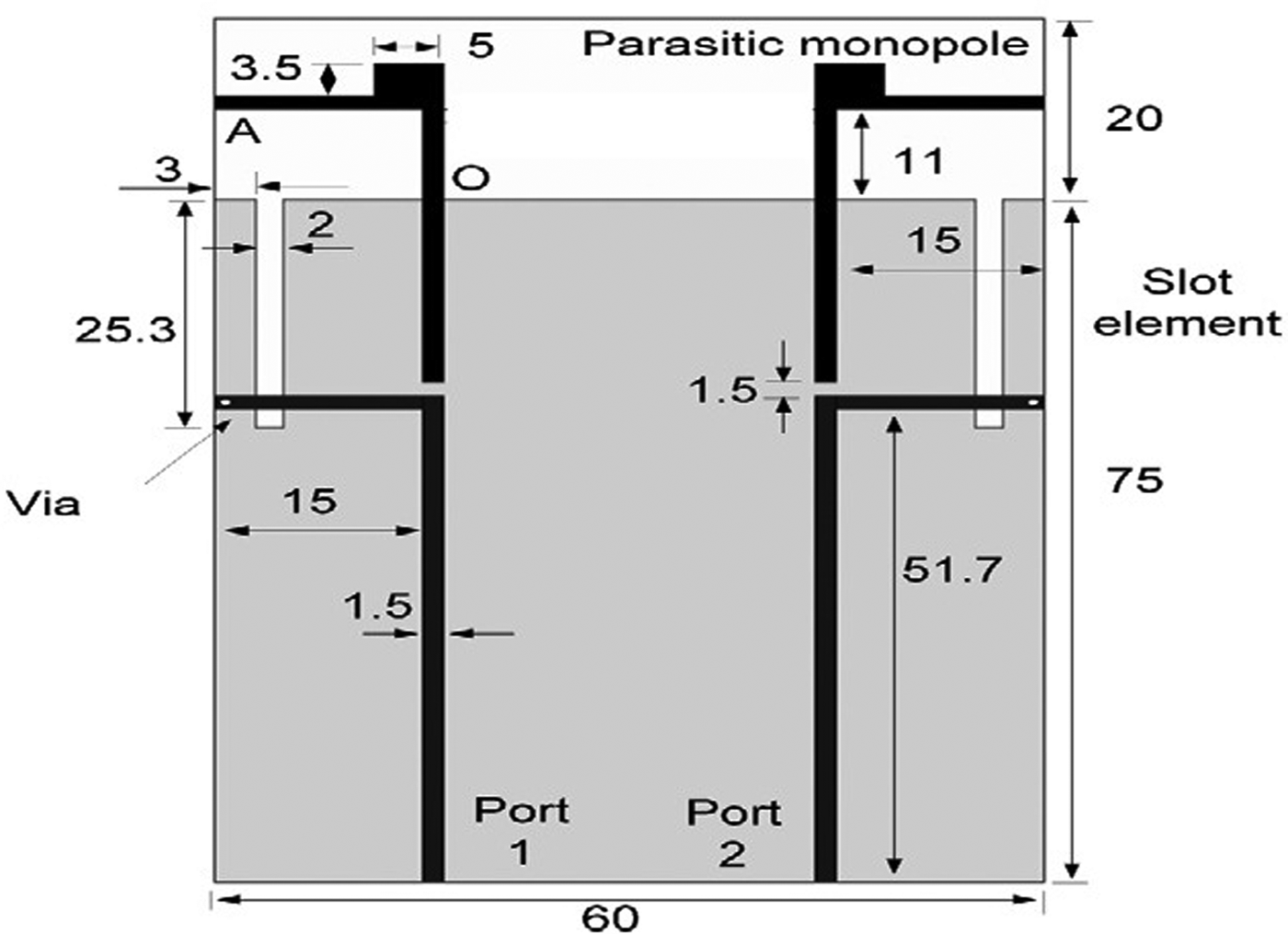
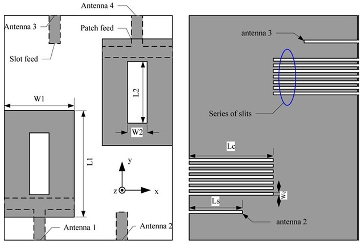
The undesired energy coupling can be limited in orthogonal polarization, since the field orientation is in cross-polarization due to the directional radiators [Reference Adamiuk, Beer, Wiesbeck and Zwick30]. MIMO with polarization diversity is also one of the approach used in cognitive radio communication for spectrum utilization [Reference Awang Da, Dzulkifli and Kamarudin31]. Polarization diversity can also be realized if orthogonal slot antennas (2 × 2) along with metal via to short ground plane are used as shown in Fig. 3 [Reference Zhang, Zetterberg and He32]. Similarly, a multi-layer approach enhances the bandwidth of a orthogonally placed PIFA elements (2 × 2) [Reference Chang, Tsai, Hsu and Liu33], whereas slotted strips in PIFA antenna aids certain amount of isolation (reduces mutual coupling) used for LTE and WiMAX applications [Reference Han and Choi34]. MIMO antenna with crossed exponentially tapered slot (XETS) was also realized as an orthogonal polarization and used for the wireless applications [Reference Costa, Lima, Medeiros and Fernandes35]. The self-balancing radiation patterns (due to the design shown in Fig. 4) [Reference Su and Lee36], port-to-port decoupling [Reference Xiong, Zhao, Li, Ying and Wang37], diversion of ground linking current [Reference Wi, Kim, Jang and Lee38], better efficiency [Reference Ghosh, Tran and Le Ngoc39], and wider bandwidth responses with required in-band isolation [Reference Koohestani, Moreira and Skrivervik40] are certain advantages of the polarization diversity MIMO antennas. The port isolation in this approach is more than 15 dB.
MIMO using slot antennas with polarization diversity © [Reference Zhang, Zetterberg and He32].

Circular loop MIMO antenna for access point application © [Reference Su and Lee36].

C) Pattern diversity
To ensure the radio link reliability in multi-path environments, MIMO antenna radiators are designed to build radiation patterns in different directions. The patterns may be complementary (180° in phase reversal) symmetric or asymmetric depending on their orientation and placement. Such approach has benefit of getting equal amount of return-loss and mutual coupling between complementary symmetric case and vice versa at different ports [Reference Malviya, Panigrahi and Kartikeyan41]. A multi-mode and multi-layered MIMO antenna with pattern diversity and with stepped profile [Reference Iglesias, Teruel, Gonzalez and Sanchez Fernandez42] was designed for bandwidth expansion, and reconfigurability of radiation patterns [Reference Piazza, Kirsch, Forenza, Heath and Dandekar43]. The pattern reconfigurability is the effect of ground current alteration [Reference Cai and Du44]. An open-loop resonator with curved slots [Reference Ramadan, Constantine, Tawk, Christodoulou and Kabalan45], and I-shaped conductor [Reference See, Abd Alhameed, Mcewan, Jones, Asif and Excell46] approaches were implemented with pattern diversity technique.
D) Parasitic element/structure approach
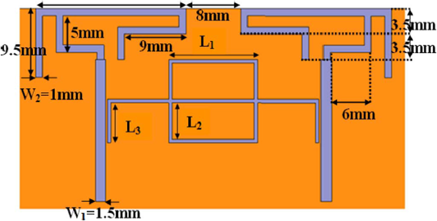
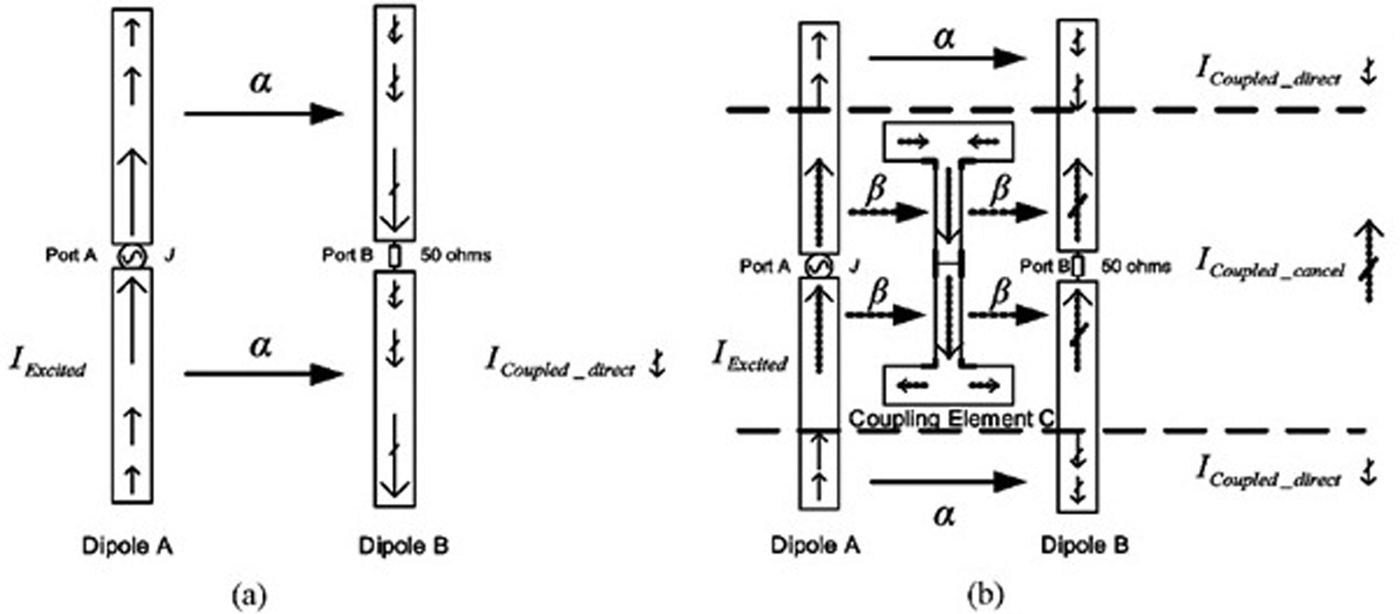
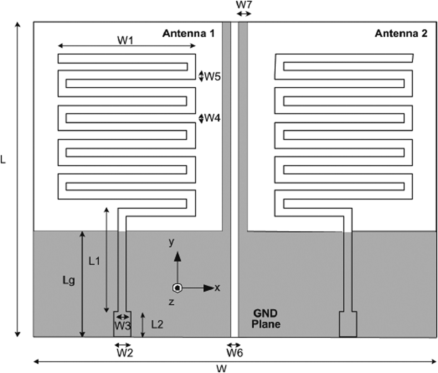
In most of the cases, an indirectly connected metallic structure is introduced between the MIMO antenna radiators, which is known as a parasitic element. The location of a parasitic element ensures the diversion of certain unwanted field/current, and to enhance some specific characteristics such as bandwidth, isolation, and efficiency [Reference Min, Kim and Moon47]. Also, a meandered line slot etched between the slotted radiating elements acts like a parasitic element [Reference Ayatollahi, Rao and Wang48] and serves the same purpose. A design with broadband technique used a parasitic structure as shown in Fig. 5 between the radiators to produce surface currents in existing coupling path to cancel out it and also to produce less ohmic losses [Reference Addaci, Diallo, Luxey, Le Thuc and Staraj49]. A parasitic element showed in Fig. 6 cancel out the field by reverse coupling approach and limits the effect of correlation between the radiators [Reference Li, Du, Takahashi, Saito and Ito50, Reference Payandehjoo and Abhari51]. Similarly, an indirectly coupled, coupling element, as shown in Fig. 7, introduces an extra current path and hence reduces coupling between the closely spaced antennas [Reference Mak, Rowell and Murch52]. However, the parasitic element approach seems to be simple, and provides effective decoupling among radiators, yet very much sensitive to the position and placement of these elements. Parasitic element results in inductive loading and forms inductor–capacitor (LC)-equivalent circuit to shift mutual coupling from desired frequency band to out of band. The port isolation in this approach is more than 10 dB.
MIMO antenna with parasitic element between radiators © [Reference Addaci, Diallo, Luxey, Le Thuc and Staraj49].

MIMO antenna with parasitic element to enforce reverse coupling © [Reference Li, Du, Takahashi, Saito and Ito50].

MIMO antenna with I-shaped coupling element © [Reference Mak, Rowell and Murch52].

E) Neutralization line approach
A neutralization line is connected between the shorting/feeding strips to reverse the amount of coupling current and hence enhances the isolation. It can be placed between radiating elements or between ground plane and radiators. It results in inductive loading and forms LC circuit due to capacitive electromagnetic coupling between radiators to produce an open circuit at a desired frequency for mutual coupling reduction [Reference Diallo, Luxey, Le Thuc, Staraj and Kossiavas53, Reference Diallo, Luxey, Le Thuc, Staraj and Kossiavas54]. A neutralization line is a kind of port decoupling technique implemented with short-circuited monopoles as shown in Fig. 8 [Reference Su, Lee and Chang55], antennas with shorting posts for directive/rotational radiation patterns [Reference Wang, Liu, Zhang, Li and Feng56], and helps to achieve wide-band characteristics [Reference Zhang and Pedersen57]. Similarly, a directly connected decoupling network is used as a neutralization line to get the dedicated radiation patterns for MIMO antenna elements. The direct connection of both radiators as shown in Fig. 9 allows the current to pass through the other (during the excitation of a single port) and protects the load from coupling current [Reference Ssorin, Artemenko, Sevastyanov and Maslennikov58]. Although the neutralization line is an easy and simple approach of decoupling radiators, searching a low-impedance path for its placement is still challenging.
MIMO antenna with neutralization line technique © [Reference Su, Lee and Chang55].

MIMO antenna with directly connected decoupling network © [Reference Ssorin, Artemenko, Sevastyanov and Maslennikov58].

F) Slit/slot-etching approach
The importance of slots and slits on different MIMO antenna designs with their advantages/disadvantages is described in this section. Different geometric shapes of slot etching into the radiating element and/or ground plane leads to the enhancement of specific characteristics like isolation (reduction in mutual coupling), wavelength shifting, and miniaturization, etc. The slot etching is a slow-wave structure technique to reduce the signal wavelength, which in turn reduces distance between the radiators and hence reduces correlation between them [Reference Andujar and Anguera59, Reference Kim and Park60]. Different slot structures play a role of isolation improver and multi-band creator [Reference Addaci61, Reference Ghouz62], i.e. J-shaped slot in ground [Reference Manteghi and Samii63]. Similarly, a slit etched in ground is a thought of a capacitive effect and helps in reducing mutual coupling between radiators [Reference Chiu, Cheng, Murch and Rowell64]. The effect of slits and slots may induce back-lobe radiation. Though, they may help in improving efficiency and ensures compactness of the MIMO.
A PIFA antenna design with C-shaped (λ/2 wavelength) slots and T-shaped slits along with λ/4 wavelength resonator controls back-lobe radiation, reduces size, and enhances efficiency. However, such design demands matching circuit to control mutual coupling [Reference Bhatti, Choi and Park65]. While using slits and slots, the problem of matching can also be seen in case of proximity-coupled feeding. Sometimes, increasing the height of patch may solve the matching problem, likewise as shown in Fig. 10 [Reference Li, Xiong and He66]. The slits not only improve isolation, but sometimes are also used to widen the bandwidth [Reference Wu, Cheung, Yuk and Liu67]. MIMO antenna design with a pair of air-insulated λ/4 wavelength slots etched in a ground plane blocks the near-field radiations and some amount of coupling current to reduce mutual coupling [Reference Zuo, Yin, Wu, Zhang and Ma68]. A combined effect of XETS and intersecting square slot with parallel-piped cavity is also used for mutual coupling reduction and wide-band operation. A cavity is introduced in a design to reduce back radiations [Reference Medeiros, Lima, Costa and Fernandes69]. However, an indirectly excited slot in a cavity-backed slot array antenna acts like a parasitic element and distorts the radiation pattern by re-radiation of energy [Reference Dumali, Raitton and Paul70]. The port isolations in this approach is more than 20 dB.
MIMO antenna with slot in patches and slits in ground © [Reference Li, Xiong and He66].

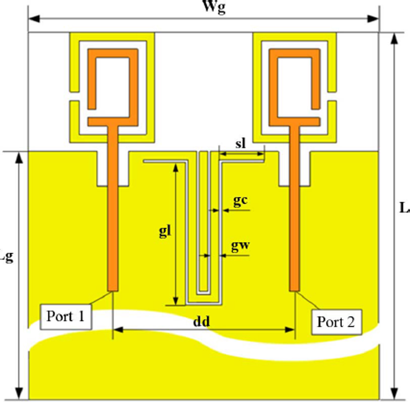
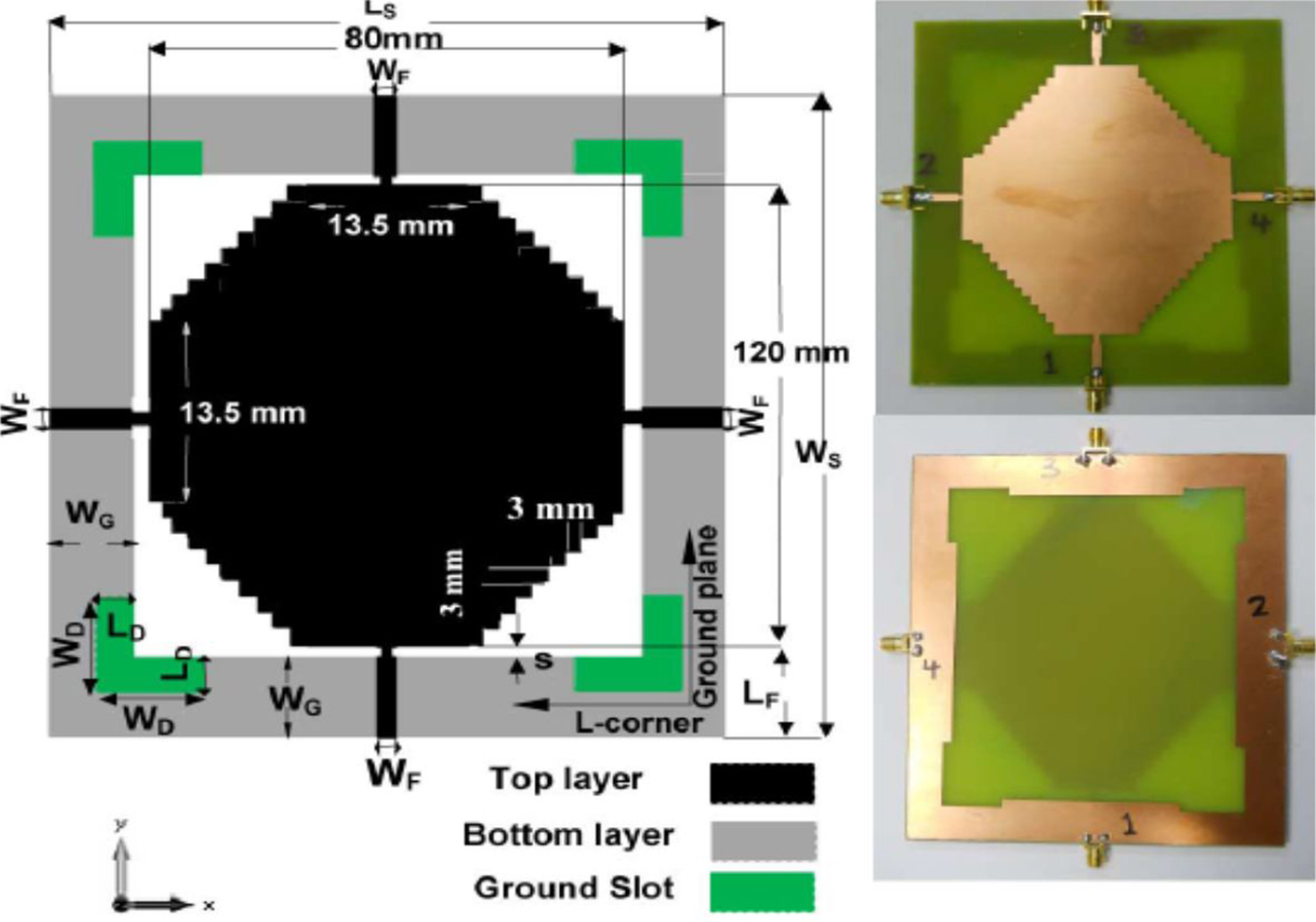
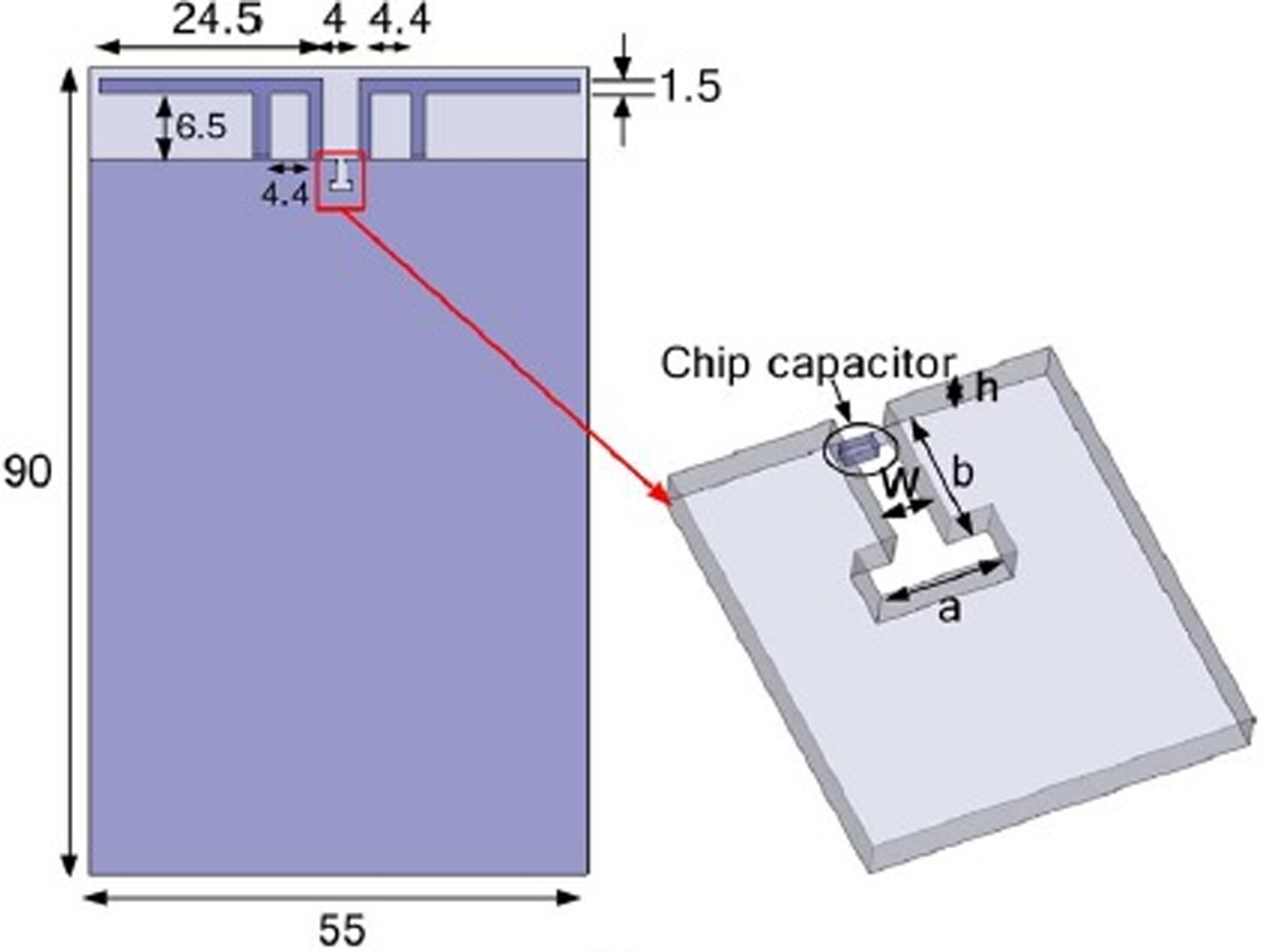
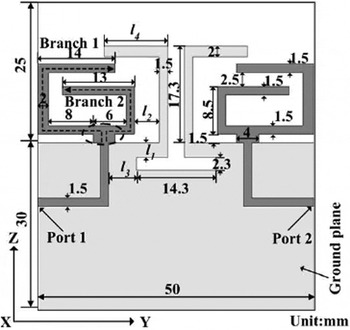
A slot etching can be a form of defected ground structure (DGS) [Reference Sonkki and Salonen71], like H-shaped slot [Reference Wei, Zhang, Chen and Feng72] and fork-shaped slot (combination of J- and L-shaped slots) [Reference Singh, Pandey, Bharti and Meshram73], to revert the direction of current flow for mutual coupling reduction. Similarly, a horn-shaped slot helps to achieve omnidirectional radiation patterns with enhanced bandwidth in a multi-antenna array system [Reference Wu, Hui and Ming74]. In elctromagnetically excited loops, decoupling can be achieved with U-shaped slot etched in a ground plane. Such technique helps to reduce mutual coupling and provides broadband features. The corresponding MIMO antenna design is shown in Fig. 11 [Reference Zhou, Quan and Li75]. Similarly, the slots etched at the corners of the ground are used to enhance the bandwidth and isolation between radiators. The design is shown in Fig. 12 [Reference Moradikorordalivand, Rahman and Khalily76]. Similarly, a MIMO antenna with a T-shaped open-ended slot and a chip capacitor as shown in Fig. 13 were combined for band rejection property and in turn reduces mutual coupling [Reference Park, Choi, Park and Sarabandi77]. The combination of slot with ground branches as shown in Fig. 14 can be used to create multi-band operation and improves in-band isolation [Reference Zeng, Yao, Liu, Yu, Xie and Chen78].
Dual-loop MIMO antenna with dual U slots in ground © [Reference Zhou, Quan and Li75].

MIMO antenna with corner slots for isolation enhancement and wide banding © [Reference Moradikorordalivand, Rahman and Khalily76].

MIMO antenna with T-shaped slot and capacitor © [Reference Park, Choi, Park and Sarabandi77].

MIMO antenna with ground slot and inverted L-shaped ground branches © [Reference Zeng, Yao, Liu, Yu, Xie and Chen78].

G) Coupling/decoupling structure approach
A through analysis of coupling/decoupling approaches has been included in this section with their advantages and disadvantages. A transmission line of λ/4 wavelength or submultiple of it is used for decoupling/descattering, and is placed at a point where the impedance is purely imaginary [Reference Andersen and Rasmussen79]. Similarly, a decoupling network converts the transadmittance of antenna ports into pure imaginary part [Reference Chen, Wang and Chung80]. Some designs use ring hybrid decoupling structure [Reference Gong, Jiao and Gong81] to control mutual coupling. The combination of both the decoupling and matching networks are required in some designs to improve antenna characteristics [Reference Cui, Gong, Liu, Jiang and Guan82]. A T-shaped ground arm also serves the purpose of port decoupling [Reference Kwon, Kim, Lee and Choi83].
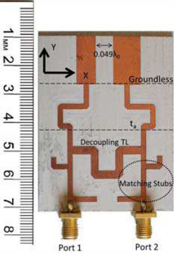
Similarly, a design uses a decoupling network with a chip capacitor and is connected to each feed line for the improvement of impedance matching and reduction of mutual coupling [Reference Kim, Han, Lee and Choi84]. A transmission line with matching network is also used for decoupling purpose in some designs [Reference Cui, Liu, Jiang, Gong, Guan and Yu85]. Similarly, a U section can also be used between the radiating elements to decouple them [Reference Farsi, Aliakbarian, Schreurs, Nauwelaers and Vanderbosch86]. A reactive decoupling structure uses a T-shaped neutralization stub between the radiators for impedance matching and good isolation condition [Reference Wu, Zhou, Wu and Ma87]. The effect of decoupling network using transmission line and matching stub as shown in Fig. 15 is utilized for decorrelation of antenna elements [Reference Moharram and Kishk88]. There are different types of decoupling networks and decoupling elements and are used according to the requirement in design [Reference Pelosi, Knudsen and Pedersen89, Reference Wang, Mauermayer and Eibert90]. Similarly, the cross-shaped arms are used as a self-decoupling structure to generate orthogonal modes, which in turn enhances decoupling properties [Reference Wang, Zhang and Feng91]. The decoupling level is more than 10 dB in this approach.
MIMO antenna with decoupling network © [Reference Moharram and Kishk88].

H) Meta-material approach/resonators
Different types of meta-material-inspired electromagnetic band gap (EBG) materials, along with their merits/demerits has been given in this section. These are specially used to control mutual coupling [Reference Yang and Samii92]. A meta-material-inspired element forms the LC-equivalent resonant circuit to shift the in-band mutual coupling elsewhere. Many of the EBG structures are available in antenna designs. These are also used to enhance certain properties of antennas to reserve the shape of radiation patterns, prevent back side reflection to increase DG, and reduces the loading effect of the adjacent antenna elements. The stacking of EBG layers offers a very low mutual coupling [Reference Payandehjoo and Abhari93].
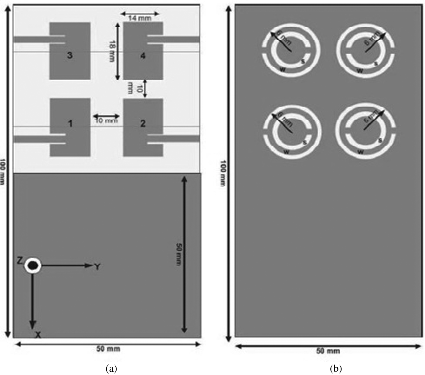
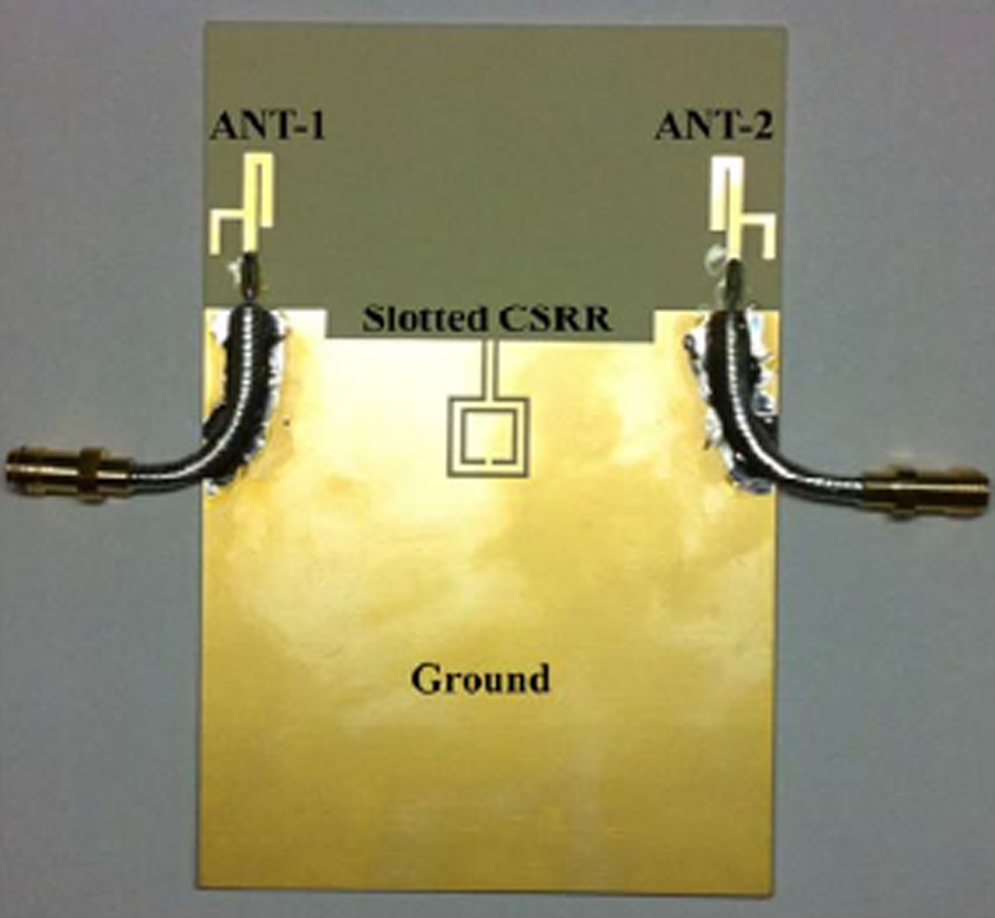
A meta-material-inspired broadband isolator is used to enhance in-band isolation [Reference Hsu, Lin and Su94]. A split-ring resonator (SRR)-loaded antenna utilizes the benefit of negative epsilon [Reference Lee, Kim and Jang95–Reference Ntaikos and Yioultsis97]. Similarly, a complementary split-ring resonator (CSRR)-loaded ground is used for size and mutual coupling reduction [Reference Khan and Sharawi98–Reference Payandehjoo and Abhari100]. The SRR and CSRR structures are available in different shapes like an open-ended ring pair as shown in Fig. 16 [Reference Sharawi, Khan, Numan and Aloi101, Reference Sharawi102]. The capacitively coupled loop is also used for the reduction of mutual coupling [Reference Sharawi, Numan and Aloi103]. The Babinet's principle can be applied to find out the field analysis of SRR/CSRR as shown in Fig. 17 [Reference Yang, Kim and Kim104]. The port isolation in this approach is more than 10 dB. The difference between the slot/slit etching in the ground and SRR/CSRR lie on their operation. As SRR/CSRR produces isolation, but results in narrow band operation, while slot/slit etching not only provides isolation, but also results in wide-band operation.
A 2 × 2 MIMO antenna with CSRR © [Reference Sharawi, Khan, Numan and Aloi101].

MIMO antenna with slotted CSRR in ground © [Reference Yang, Kim and Kim104].

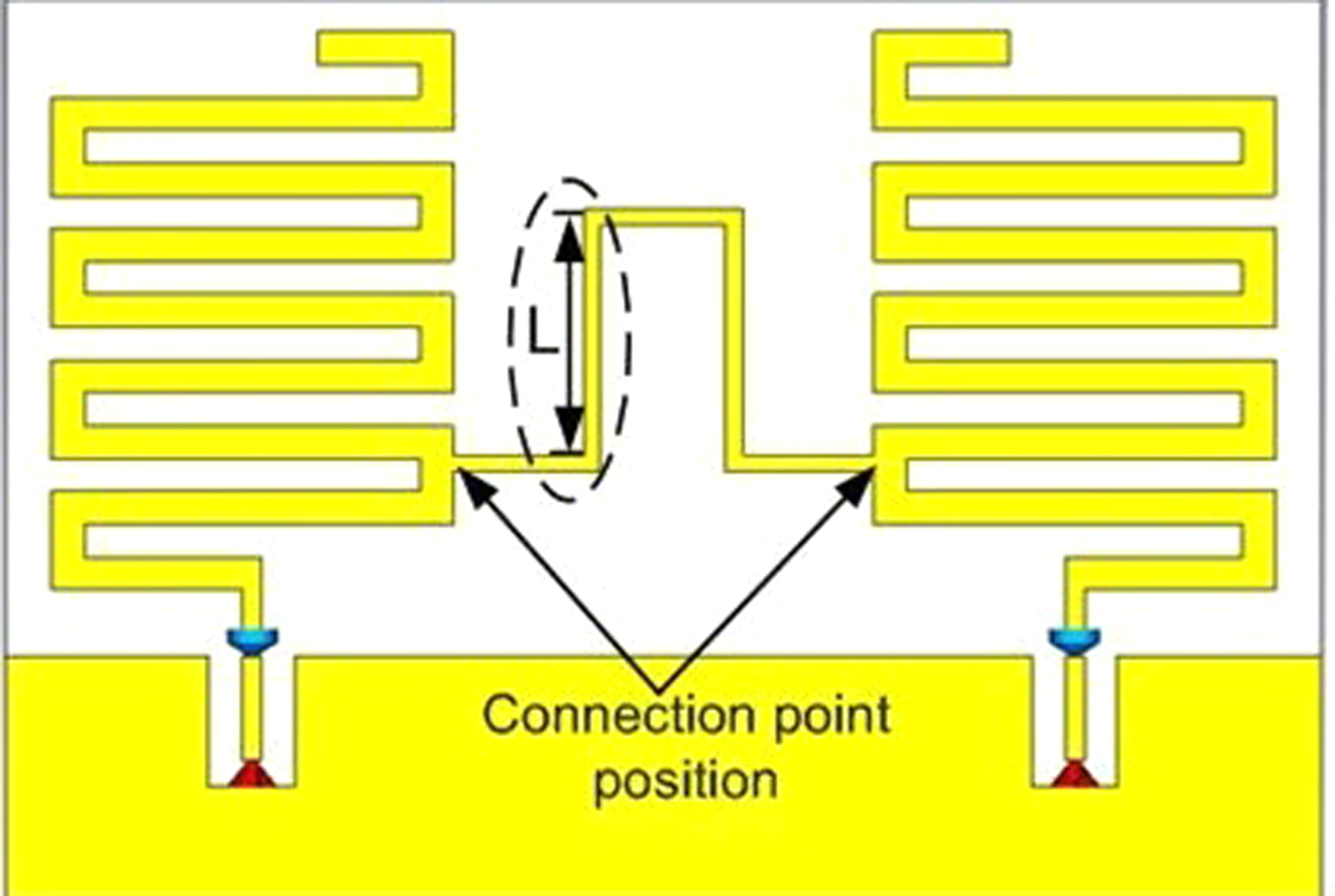
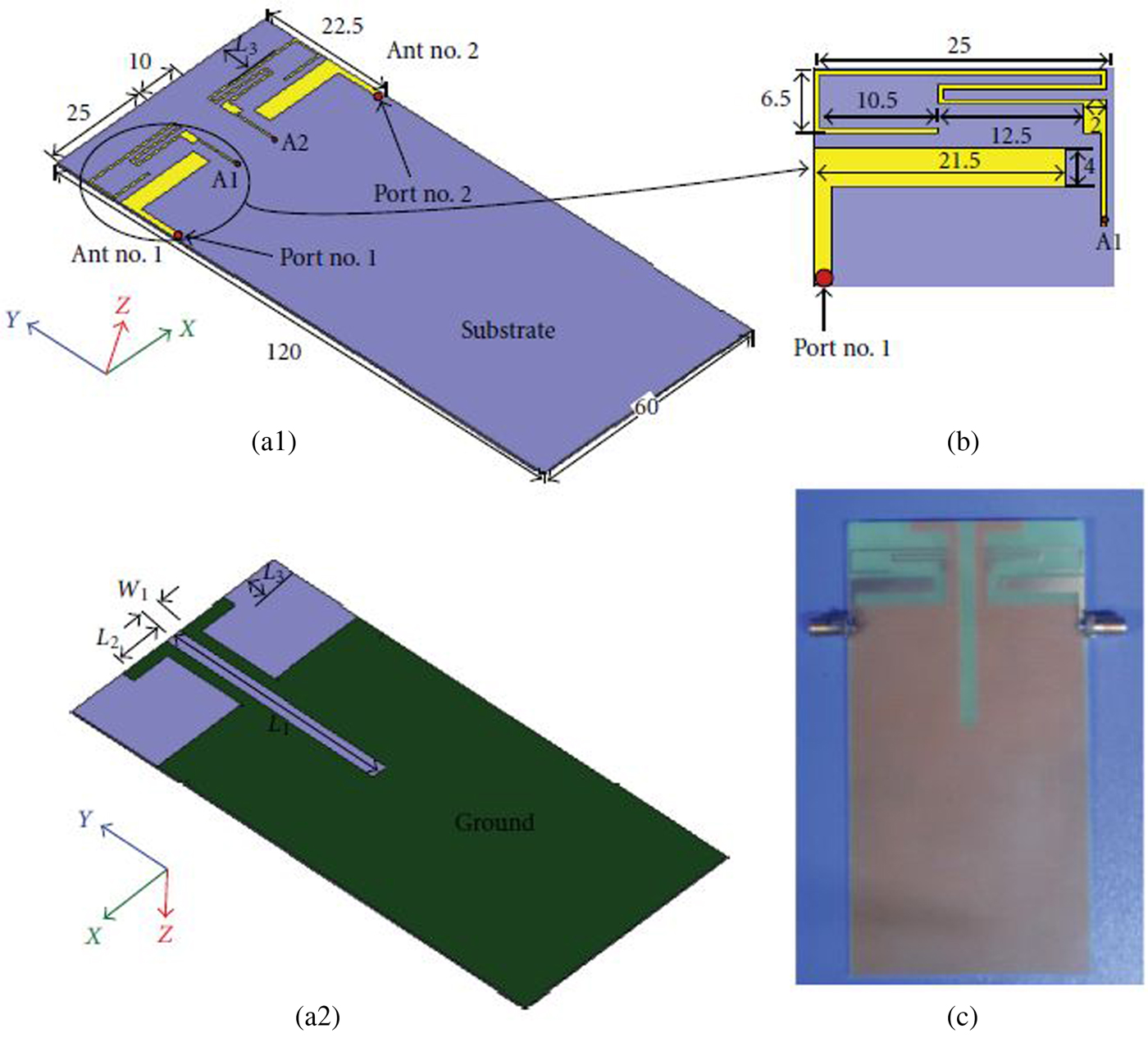
Similarly, a complementary pattern approach using a composite right/left-handed (CRLH) meta-material transmission line reduces mutual coupling and size of the radiators. The CRLH can be analyzed using a LC-resonant structure [Reference Hwang, Yang, Byun and Kim105]. Similarly, a slotted meander-line resonator as shown in Fig. 18 is used to create defects between radiators, which in turn produces band notch operation to control the mutual coupling effects [Reference Alsath, Kanagasabai and Balasubramanian106]. Also, to capture and control the surface currents of a radiator, a modified serpentine structure is inserted between the radiators [Reference Arun, Sharma, Kanagasabai, Velan, Raviteja and Alsath107]. A polarization diversity MIMO antenna utilizes the benefits of SRR by loading it between the radiators to offer multi-band operation with low mutual coupling, and reduction in size [Reference Cheng, Sun, Lu and Zhu108]. Having been enriched with many advantages, this approach results in slow wave structure, narrow band operation, as well as in low efficiency.
MIMO antenna with slotted meander line resonator © [Reference Alsath, Kanagasabai and Balasubramanian106].

I) Metallic/shorting strips/stubs
In most of the MIMO antenna designs, a PIFA array antenna uses the shorting strips/posts for size and mutual coupling reduction [Reference Browne, Manteghi, Fitz and Samii109]. The shorting pins/posts are used for the inductive loading, and in turn to form appropriate LC-equivalent circuit to control mutual coupling effects. The cross-polarization phenomena was seen in case of shorting pins/posts to distort co-polarization as well as gain pattern of the antennas. The effect of cross-polarization was reduced by meandering probe feeding of a W-shaped antenna structure. The design results in high bandwidth and was suitable for array application for LTE bands [Reference Shakib, Islam and Misran110]. A broadside and conical patterns are also achieved with mode excitation by shorting posts and L-shaped probe feeds [Reference Lung, Yang, Luk, Lai, Kishk and Lee111]. Thick circular patch with grounding pins/posts are also used in designs for specific characteristics [Reference Callaghan and Batchelor112]. A multi-branch MIMO antenna with a shorting strip and an isolation stub was utilized for portable wireless devices to divert the coupling current [Reference Ling and Li113]. In such designs, the effect of shorting strip is to create the current loops, and in turn controls the direct-coupled currents [Reference Singh, Meruva, Pandey, Bharti and Meshram114, Reference Chacko, Augustin and Denidni115]. Although the approach seems to be beneficial for size reduction, gain enhancement, and mutual coupling reduction, the resulted structures become complex and increases the weight of overall structure.
J) Feeding networks
A common feed enhances radiation efficiency and gain, counter attacks on the channel fading due to multi-path propagation, and provides beam steering in radiation pattens [Reference Khawaja, Tarar, Tauqeer, Amir and Mustaqim116]. A 180° asymmetrical T-shaped power divider (to avoid feed overlapping) [Reference Wang, Feng and Luk117], U-shaped folded feed line (power divider) structure [Reference Lu, Kuai, Zhu and Zhang118], L-shaped feed structure [Reference Antonino Davin, Cabedo Fabres, Bernardo Clemente and Bataller119], crossed feeding network [Reference Sim120], four-shaped feed structure [Reference Sharawi, Jan and Aloi121], coupled feed [Reference Li, Lin and Yang122], capacitive feed [Reference Li, Chen, Zhang, Zhou and You123], and mixed micro-strip and coplanar feed [Reference Wong, Islam and Kibria124] are used to control certain characteristics like mutual coupling between radiators. These feed structures also form the LC-equivalent circuits. Feeding networks with insufficient space between radiating elements result in inappropriate gain/isolation, and always have bigger sizes, though, these structures are easy to design and implement.
K) Ground branches/utilization
Different shapes of inverted/non-inverted L and T ground branches help in reduction of mutual coupling. Such branches have different effects on low/high frequencies [Reference Ding, Du, Gong and Feng125, Reference Shoaib, Shoaib, Shoaib, Chen and Parini126]. Similarly, a MIMO design has two isolation approaches, first that looks into the depth of the ground and other looks between the radiators in terms of partially extended ground arms as shown in Fig. 19 [Reference Sharawi, Iqbal and Faouri127]. In many of the applications L/T ground branches are used with matching stubs [Reference Panda and Kshetrimayum128, Reference Lu and Li129] for proper impedance matching as shown in Fig. 20 [Reference Yang, Yao, Yu, Xie and Chen130]. Few designs take the benefit of wide-band characteristics using L-protruded branches and T-shaped slots along with mutual coupling reduction as shown in Fig. 21 [Reference Xia, Chu and Li131].
MIMO antenna with ground split and ground arms © [Reference Sharawi, Iqbal and Faouri127].

MIMO antenna with T-shaped ground branch © [Reference Yang, Yao, Yu, Xie and Chen130].

MIMO antenna with T slot and protruded L branches in ground © [Reference Xia, Chu and Li131].

Similarly, the effect of multi-grounds in a MIMO design with inductive coil produces additional resonance and reduces mutual coupling effects [Reference Zhao and Choi132]. A mutual coupling reduction and impedance bandwidth improvement approach uses embedded protruded ground arm between the radiators for MIMO antenna design [Reference Ban, Chen, Chen, Kang and Li133]. The effects of mutual coupling may also be controlled by combining the effects of inverted L branches and a loop etched in a ground as shown in Fig. 22 [Reference Shoaib, Shoaib, Shoaib, Chen and Parini134]. The ground can be utilized as a reflector and to excite less surface currents in a directive multi-loop MIMO antenna design [Reference Su and Lee135]. The port isolation in this approach is more than 10 dB. The ground branch approach is easy and simple, although placement on unwanted place may result in reduction of gain and enhancement in mutual coupling.
MIMO antenna with ground slot and inverted L branches © [Reference Shoaib, Shoaib, Shoaib, Chen and Parini134].

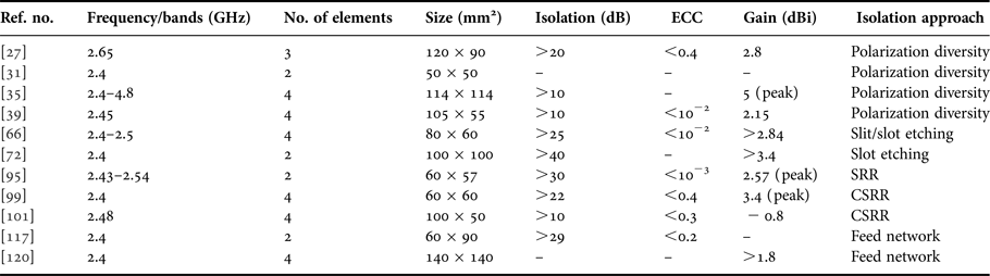
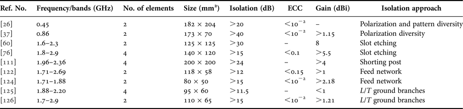
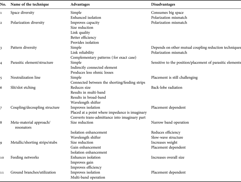
All the above diversity and mutual coupling reduction techniques are compared with their diversity performance using frequency bands/resonant frequencies, number of elements, size, isolation, and ECC as showed in Tables 1–3. The amount of isolation is dependent on the type of radiating elements, diversity technique, their placement, orientation, and the type of mutual coupling reduction technique used. For example, the ground branches/utilization approach is simple and suitable to design LTE operations such as 700, 800, and 900 MHz frequency bands using meander line or monopole radiators. The advantages and disadvantages of diversity and mutual coupling reduction techniques are compared in Table 4.
Comparison of considered references for WLAN band

Comparison of considered references for WLAN/WiMAX bands

Comparison of considered references for LTE bands

Comparison of diversity and mutual coupling reduction techniques

III. MIMO ANTENNA MINIATURIZATION
The miniaturization and space utilization are two of the important aspects of MIMO antenna designs and must be optimized for the present/future mobile communications [Reference Vainikainen136]. As the antenna is an energy transformation device to transform the wave generated by the antenna into the radiating wave and vice versa. The reduction in the separation between MIMO antenna radiators affects transformation of energy and in turn discussed antenna parameters. The miniaturization of a MIMO antenna is concerned with the type of radiating element and ground. The most of the above discussed approaches of mutual coupling reduction serves the dual purpose. They not only help in reduction of mutual coupling, but also reduce the overall size of MIMO antennas for the present/future wireless communications. The first part of mutual coupling reduction approaches has already been presented thoroughly in previous section.
In first approach, high degree of miniaturization may be achieved with dielectric material loading, though such materials are very much expensive, and much care is needed in their designing and placement. Another disadvantage of this approach is that it has limited bandwidth [Reference Staub, Zurcher and Skrivervik137, Reference Shin, Choi, Kim and Park138].
The second approach of size reduction uses folding and shorting pins/posts. This approach provides four times of reduction in size, but has cost-effective solutions and non-planar structure with complex geometry. This approach also has no specific design rules. In a PIFA design, a meander line with the rectangular patch was combined for size reduction. A MIMO antenna with such design was utilized for SM transmission [Reference Wang, Zhang, Plettemeier, Ohlmer and Fettweis139]. Similarly, a 2 × 1 MIMO miniaturization with the meander line was used to make electrically small antenna to operate at low-frequency band [Reference Sharawi, Faouri and Iqbal140]. This approach takes the benefit of reactive impedance, exists due to the short circuiting (with via) in PIFA antennas [Reference Chiu, Shum and Chan141], and also in inverted F antenna with stub loading [Reference Mendez, Herrera, Leal, Miranda and Aguilar142].
n the third approach of size reduction, different patch shapes and slots are used, especially a fractal (having space-filling property) geometric patch provides eight times of miniaturization, and slots can provide wider bandwidths. This approach using fractal has complex geometry and has no standard design procedure [Reference Best and Morrow143, Reference Vishvakarma and Vishvakarma144]. The reconfigurable slot antenna can be used to alter many of the required MIMO antenna characteristics and helps in miniaturization [Reference Soliman, De Raedt and Vanderbosch145–Reference Anh and Ook147].
In the fourth approach of size reduction, ground is modified according to the requirement of MIMO antenna design. This approach also provides eight times of miniaturization, and is a planar and simple geometry, and also no standard design procedure is followed here. The drawbacks of this approach are that it provides increased the back-lobe level, and also reduces efficiency. In this approach, slots in the ground are also used for multi-banding and isolation enhancement. The slots in ground may be in the form of symmetric/asymmetric/square/rectangle shape [Reference Gosalia and Lazzi148, Reference Maddani, Sameena and Mulgi149], and in the form of DGS to achieve matching conditions [Reference Yu, Wang, Gao and Lu150].
In the fifth approach of size reduction, meta-materials such as ε r negative, μ r negative, double negative, and meta-material-inspired resonators/techniques are used. This approach has high degree of miniaturization, but low efficiency, low bandwidth, and complex geometric structures, and no standard design procedure. These meta-materials are loading in ground plane/patch/both in the form of SRR [Reference Arora, Pattnaik and Baral151] or CSRR [Reference Xie, Li, Zhu and Liang152].
IV. CONCLUDING REMARKS
The MIMO antennas are used to solve the problem of SISO antennas. On the other hand, their performance factors like gain, efficiency, MEG, and DG all are affected, due to the close proximity of MIMO antenna elements. The degradation in these parameters is due to the radiation and emission properties of radiators and ground, which is commonly encountered as a mutual coupling. A thorough literature review was presented to control the degrading factors of mutual coupling between the radiating elements. The impact of space/pattern/polarization diversity techniques was presented with their merits and demerits to control this factor. Similarly, the effect of parasitic element/structure, neutralization line, slits/slots, coupling/decoupling structures, meta-materials, metallic/shorting pins/stubs, feeding networks, and ground branches/utilization approaches was presented in depth with their utilizations in different designs to control mutual coupling.
Most of the considered techniques not only provides reduction in mutual coupling but also helps in miniaturization of the radiating elements. Therefore, these techniques are more important because these are capable in producing compact MIMO antennas for the present/future wireless communications. Each of the mutual coupling reduction technique loads a certain value of capacitance/inductance in between the radiating elements and forms a series/parallel resonance circuit to shift the in-band mutual coupling on the undesired frequency spectrum. The considered mutual coupling reduction techniques and their values are dependent on the type of radiating elements as well as orientation and placement of radiating elements.
 Leeladhar Malviya received his B.E. degree in Electronics and Telecommunication, from the Govt. Engineering College, Ujjain (MP), India, in 1998, M.E. degree in Electronics and Telecommunication, from Shri G. S. Institute of Technology and Science, Indore (MP), India, in 2008. Currently he is pursuing Ph.D. from Indian Institute of Technology Roorkee, India. His area of interest is MIMO antenna design for wireless applications.
 Rajib Kumar Panigrahi received his Ph.D. degree from IIT Guwahati in 2011. He has received his M.Tech. degree in Electronics with specialization in microwave engineering from Cochin University of Science and Technology and B.E. degree in Electronics and Communication from Bangalore University (now VTU). Since 2012, he has been with the Department of Electronics and Communication Engineering, Indian Institute of Technology, Roorkee, where currently he is an Assistant Professor. His research interests include Radar-based remote sensing, SAR image denoising and segmentation and classification of SAR images.
 M. V. Kartikeyan received the M.Sc. and Ph.D. degrees in Physics and Electronics Engineering from Banaras Hindu University, Varanasi, India, in 1985 and 1992, respectively. He was with Institut für Hochleistungsimpuls-und Mikrowellentechnik, Karlsruhe Institute of Technology, Karlsruhe, Germany, as an Alexander von Humboldt Fellow. He is a Full-Professor in the Department of Electronics and Communication Engineering, Indian Institute of Technology, Roorkee, India, since 2009. His current research interests include millimeter/THz wave engineering (high-power devices and allied components), microstrip antennas for communications, microwave-integrated circuits, and RF and microwave design with soft computing techniques.