Introduction
One of the most important quantities in all of optics is the refractive index. This is particularly true in the subfield of optical coatings, where the refractive index appears in virtually every equation as a figure of merit. However, in the design of optical coatings, the choices of optically transparent materials with a wide range of refractive index values are quite limited. Gases are materials with the lowest refractive index (n air ≈ 1.0), but they completely lack structural stability. MgF2, CaF2, and SiO2, which have refractive indices n MgF2 = 1.39, n CaF2 = 1.44, n SiO2 = 1.46, respectively, are materials with refractive indices among the lowest available for conventional, dense materials. The limited availability of materials across a wide range of refractive index values and the unavailability of very low-n materials for optical thin-film applications can strongly limit the performance of optical coatings.
Recently, nanoporous materials with both tailorable- and low-refractive index properties have been explored for their customizable optical characteristics.Reference Xi, Kim, Schubert, Ye, Juneja, Lu and Lin1–Reference Wang, Lai, Lin, Lin and He8 By controlling the porosity of such nanoporous films, the effective refractive index of the grown or deposited film can be controlled. The refractive index may be tailored within a wide range of values, from the value of the dense bulk material down to values close to the index of air. These two properties—tailorability of the refractive index and ability to attain very low-refractive index values—make nanoporous coatings ideally suited for achieving the highest possible performance in optical coatings.
Oblique-angle deposition
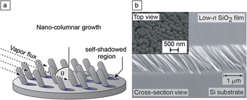
One particularly promising method to fabricate nanoporous films with highly desirable optical properties is oblique-angle deposition. Films deposited using oblique-angle methods have shown excellent control over the morphology and thickness of the deposited layers.Reference Xi, Kim, Schubert, Ye, Juneja, Lu and Lin1–Reference Robbie, Friedrich, Dew, Smy and Brett4, Reference Hawkeye and Brett9–Reference He and Zhao11 By controlling the vapor-flux incident angle during deposition, the porosity and thus the refractive index of the nanoporous film can be arbitrarily tailored. Oblique-angle deposition has enabled the fabrication of films with very high porosity, resulting in the lowest refractive index for a thin-film material ever reported, n ≈ 1.05.Reference Xi, Schubert, Kim, Schubert, Chen, Lin, Liu and Smart3 Further, the nature of the oblique-angle process easily lends itself to a wide variety of material systems and grants the control necessary to engineer specific nanostructure morphologies. Nanoporous optical films have been fabricated by oblique-angle deposition using electron-beam evaporation.Reference Xi, Kim, Schubert, Ye, Juneja, Lu and Lin1–Reference Robbie, Friedrich, Dew, Smy and Brett4, Reference Hawkeye and Brett9–Reference He and Zhao11 Oblique-angle deposition is a method to grow thin films with a porous nanostructure, driven by competitive growth due to the self-shadowing nature of the deposition process. Figure 1a shows the basic principle of oblique-angle deposition.Reference Lakhtakia and Messier12
(a) The oblique-angle deposition process with deposition angle θ and illustration of self-shadowing. (b) Scanning electron microscopy images of 1 μm thick thin film consisting of 80% nanoporous SiO2 that forms an array of nanorods.

A random growth fluctuation on the substrate surface will produce a shadow region that the incident vapor flux cannot reach and a non-shadow region where incident flux deposits preferentially. As deposition continues, areas of larger height variation will preferentially grow at the expense of shadowed regions, thereby creating an array of oriented nanorod material. For example, SiO2 nanorod films are routinely grown by oblique-angle electron-beam deposition on Si substrates with a vapor flux incident angle θ of 80°.Reference Xi, Kim, Schubert, Ye, Juneja, Lu and Lin1 Optical inspections have revealed a smooth specular surface with no indication of scattering. A scanning electron microscope (SEM) image of a highly nanoporous SiO2 film is shown in Figure 1b. The cross-sectional SEM clearly shows the tilted array of SiO2 nanorods and the nanoporous nature of the film.
Optical properties of nanofilms
Because the scale of the nano-feature sizes in the film is much smaller than the wavelength of the light of interest, nanoporous films can be considered to be optically homogeneous mixtures of air and the dense source material. Therefore, as an approximation, the effective refractive index of a nanoporous film may be considered to be the linear volume ratio of the dense source material and the air present in the porous film.
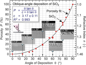
For optical films, two important characteristics exist: the refractive index and thickness of the film. Formulas accurately predicting these values for such nanoporous coatings, at a given vapor flux incident angle, are highly desirable. The qualitative tenets of oblique-angle deposition were laid out over a century ago, and there have been a number of studies on the structure of obliquely deposited thin films.Reference Kundt13–Reference Jensen and Brett20 Much research has been done to understand the structure and underlying growth processes for such nanoporous films. One of the earliest attempts to explain the orientation of nano-column growth with respect to the incident angle of deposition was by Nieuwenhuizen and Haanstra, who developed the so called “tangent rule,” which relates the nano-column growth angle to the incident angle of flux.Reference Nieuwenhuizen and Haanstra21 Later, analytic relations by Tait et al. were proposed to find better agreement between experimental data and theoretical predictions over a wider range of deposition angles.Reference Tait, Smy and Brett22–Reference Lichter and Chen24 More recently, Poxson et al. proposed a geometric theoretical model accounting for surface diffusion effects, and the model was verified to accurately predict the refractive index as a function of deposition angle over all possible deposition angles and a wide variety of material types.Reference Poxson, Mont, Schubert, Kim and Schubert25, Reference Krause, Taschuk, Harris, Rider, Wakefield, Sit, Buriak, Thommes and Brett26Figure 2 shows the porosity and refractive index of such nanoporous films as a function of deposition angle; the figure also shows several SEM images of nanoporous SiO2 films deposited by oblique-angle deposition. The result of the quantitative theoretical model is shown by the solid line, which matches the experimental results for SiO2 deposition very well.Reference Poxson, Mont, Schubert, Kim and Schubert25, Reference Krause, Taschuk, Harris, Rider, Wakefield, Sit, Buriak, Thommes and Brett26 Such formulas accurately predicting the refractive index for a given deposition angle are highly desirable in the design and fabrication of optical coatings.
Porosity and refractive index of nanoporous SiO2, inferred from a theoretical model of porosity, P (black line), and from experiments (red dots), plotted as a function of the deposition angle, where c is the porosity equation fitting parameter. R 2, mean square error between the fit and data.Reference Poxson, Mont, Schubert, Kim and Schubert25 Also shown are scanning electron microscopy images of nanoporous SiO2 films for a variety of deposition angles.

Because of the general lack of transparent materials with desired refractive index values and because no dense materials with very low-n values are available, one may be forced to select a material that is not ideal in terms of refractive index, mechanical hardness, lattice constant, or transparency. Therefore, a balance often must be struck between material availability, an application’s specific requirements, and overall optical coating performance. However, by utilizing nanoporous material systems in conjunction with a predictive quantitative model, a new paradigm becomes available in the design of high-performance optical coatings. Optical coatings can be designed and optimized for the highest possible optical performance, and films with virtually any desired refractive indices and thicknesses may be deposited to achieve the optimum performance of a coating.
Antireflection coatings
Widely used applications of thin optical films are antireflection (AR) coatings. AR coatings for solar cells reduce the reflection at the surface of solar cells; this directly increases the amount of light entering the cell and thus the overall efficiency of the cell. Simple AR coatings for solar cells consist of single-layer quarter-wave transparent films, typically silicon nitride for silicon solar cells. These coatings provide good AR characteristics at the designed wavelength and angle of incidence. However, the performance of such quarter-wave coatings falls off significantly when deviating from the optimum wavelength or angle of incidence. This is particularly problematic for AR coatings applied to solar cell devices. Because sunlight is inherently broadband, its angle of incidence changes throughout the day, and 20% of the light is diffuse.
The desire for the perfect, broadband, omnidirectional AR coating is not new. In 1880, Lord Rayleigh analyzed reflections of waves from graded refractive index interfaces between two dissimilar media. He correctly concluded that for an infinitely thick, continuously graded AR coating with the refractive index graded from the ambient medium to the substrate medium, Fresnel reflections approach zero for all wavelengths and angles of incidence. Fresnel reflections are optical reflections that occur because of a refractive index contrast between two different mediums. An example of such a near continuously graded antireflection coating occurs naturally in the Earth’s atmosphere. The refractive index of the atmosphere is effectively graded because of the continuous density change of atmospheric gases as a function of altitude. The result is a smooth gradation of refractive index. Because there is no refractive index contrast between open space and Earth’s atmosphere, very little light is reflected off of the atmosphere at any incident angle.
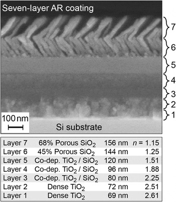
For over a century, much of the research on broadband and omnidirectional AR coatings, motivated by Lord Rayleigh’s insight, has focused on coating-design schemes that are continuously graded or that approximate continuous grading by utilizing multiple discrete layers. Recently, a discrete seven-layer, step-graded-refractive-index (GRIN) AR coating, approximating the continuous quintic profile,Reference Southwell27 was designed for the wavelength range of 400−1600 nm and for incident angles of 0−60° and subsequently fabricated.Reference Kuo, Poxson, Kim, Mont, Kim, Schubert and Lin28 By utilizing tailored- and low-refractive index materials, this seven-layer GRIN AR coating offers significant improvement to overall AR performance over traditional AR coatings. The reported average reflectance over these ranges was only 3.79%. The discrete seven-layer GRIN AR coating is pictured in Figure 3, where an SEM image is shown along with refractive index and layer thickness information. Based on the reduction in reflectance, and a corresponding increase in photocurrent, the calculated improvement in overall device efficiency for a silicon solar cell device utilizing such a discrete seven-layer GRIN AR coating compared to that of a single-layer quarter-wave coating is 18%.Reference Kuo, Poxson, Kim, Mont, Kim, Schubert and Lin28
Scanning electron microscopy image of graded refractive index seven-layer antireflection coating utilizing co-deposited bulk layers as well as tailored- and low-refractive index nanoporous layers.Reference Kuo, Poxson, Kim, Mont, Kim, Schubert and Lin28

Design of AR coatings
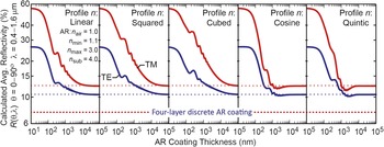
However, despite the significant AR performance improvement of this seven-layer AR coating over that of traditional single-layer AR coatings, its reflectance values are still not zero. One reason is that, in practice, a fundamental constraint exists: The refractive index boundaries of an AR coating are limited by the lack of available materials with refractive indices close to that of the substrate (e.g., Si) and close to that of the ambient medium (e.g., air). As a result, refractive-index gaps exist that result in unavoidable reflectance at these two boundaries. This is particularly true for many semiconductors such as Si, whose refractive index is large in comparison to the highest available index from transparent oxides. In an effort to better understand the effects of such refractive index gaps, the calculated average reflectance of several different continuous GRIN profiles as a function of coating thickness was recently analyzed. Each profile contains the same limiting refractive-index gaps (refractive-index discontinuities) and has a smooth and continuous grading of the refractive index. The results are shown in Figure 4.Reference Schubert, Poxson, Mont, Kim and Schubert29 Because of the refractive-index gaps at the boundaries between AR coating and substrate and ambient medium, it has been suggested that all infinitely thick, continuously graded AR coatings with such inherent refractive index gaps approach the same fundamental limiting reflectance value, as illustrated in Figure 4.Reference Schubert, Poxson, Mont, Kim and Schubert29 It is interesting to note that the way in which a continuous coating is graded can significantly alter how quickly the fundamental limiting reflectance value is reached.
Calculated average transverse electric (TE) and transverse magnetic (TM) reflectance (R) values from wavelengths 400−1600 nm and incident angles 0−90° of continuous step-graded refractive index (GRIN) antireflection (AR) coatings with different refractive-index profiles as a function of coating thickness. Also shown is the reflectivity of a 700 nm thick four-layer discrete-step AR coating. Surprisingly, the four-layer discrete-step AR coating has the lowest reflectivity, clearly better than that of infinitely thick continuous GRIN coatings.Reference Schubert, Poxson, Mont, Kim and Schubert29

Despite the existence of a limiting reflectance value for infinitely thick, continuous GRIN coatings, it has been shown that coatings consisting of several discrete layers (having discrete refractive-index steps) are able to achieve reflectance values far below this limit for coatings designed for specific wavelength and angle ranges.Reference Poxson, Schubert, Mont, Schubert and Kim30, Reference Chhajed, Schubert, Kim and Schubert31 A computational genetic algorithm method was employed to design optimized discrete-layer profiles that intentionally utilize optical interference effects for AR coatings.Reference Schubert, Mont, Chhajed, Poxson, Kim and Schubert32 The computational genetic algorithm method is an active optimization scheme for AR coatings. With this method, virtually any figure of merit can be taken into consideration. Using concepts from biology, namely selection, mutation, and combination, AR films optimized for specific applications can be designed. Furthermore, the computational genetic algorithm method is an application-specific optimization method because factors such as material availability, angles of incidence, device responsivity curves, and relative weighting of the solar spectrum can easily be used to achieve the optimum performance under specific conditions. It has been shown through this method that interference coatings utilizing discrete tailored- and low-refractive index layers are able to achieve broadband and omnidirectional AR characteristics with reflectivities lower than what is possible for a continuously graded AR profile.Reference Schubert, Poxson, Mont, Kim and Schubert29–Reference Chhajed, Schubert, Kim and Schubert31
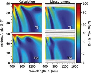
To demonstrate how discrete layer AR coatings can outperform continuously graded coatings, an optimized discrete four-layer AR coating was designed by the computational genetic algorithm.Reference Schubert, Poxson, Mont, Kim and Schubert29, Reference Schubert, Mont, Chhajed, Poxson, Kim and Schubert32 This four-layer AR coating was calculated using the same refractive index gaps as the continuous GRIN coatings shown in Figure 4. The calculated average reflectance of this discrete four-layer AR coating with a thickness of approximately 700 nm is also plotted against the average reflectivity of the continuously graded AR coatings in Figure 4. The four-layer AR coating utilizing optimized interference effects outperforms the infinitely thick, continuously graded refractive index profiles across a wide range of angles and wavelengths.Reference Zhao, Ye, Wang and Lu16 To experimentally demonstrate the performance of such multilayer coatings, a discrete four-layer AR coating utilizing tailored- and low-refractive index layers was fabricated on a Si substrate. The calculated and measured transverse electric and magnetic wave reflectance is shown in Figure 5. Reflectance measurements of this discrete four-layer AR coating were taken from 10°−80° and 400−1600 nm and found to be in excellent agreement with the calculation.Reference Zhao, Ye, Wang and Lu29
Excellent agreement is shown between calculated and measured transverse electromagnetic, TE and TM, reflectance (R) values of a discrete four-layer antireflection coating utilizing tailored- and low-refractive index layers fabricated on a Si substrate.Reference Schubert, Poxson, Mont, Kim and Schubert29

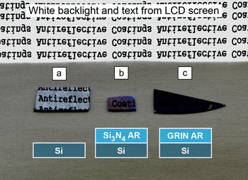
As final visual evidence, the superior performance of a discrete three-layer AR coating is shown in Figure 6; the photograph shows the white back light and text from an LCD screen and the reflected light off of Si, Si with a Si3N4 quarter-wave AR coating, and Si with a discrete three-layer AR coating utilizing nanoporous layers. It can clearly be seen that the reflected light from the quarter-wave coating is bluish, while there is virtually no discernable reflection from the three-layer AR coating.Reference Poxson, Schubert, Mont, Schubert and Kim30
Photograph of (a) reflection off of bare Si, (b) blue reflection off of a quarter-wave Si3N4 antireflection (AR) coating on Si, and (c) virtually no reflection off of a three-layer AR coating utilizing tailored- and low-refractive-index SiO2 layers on Si, all positioned so that light emitted by a monitor should be reflected.Reference Poxson, Schubert, Mont, Schubert and Kim30 GRIN, graded-refractive-index.

The key to the excellent AR performance of this discrete three-layer coating is the intentional utilization of interference effects that result from the refractive index contrasts between the two interfaces of the AR coating—one at the substrate side and one at the ambient-medium side. These interference effects are, in fact, beneficial for the performance of the AR coating.Reference Schubert, Poxson, Mont, Kim and Schubert29 Optimized interference coatings are able to have significantly better broadband and omnidirectional AR characteristics as compared to traditional single-layer quarter-wave AR coatings and even continuously graded GRIN AR coating profiles.
Conclusion
This article shows that tailored and low-refractive index nanoporous material systems hold enormous promise for a variety of optical applications. A quantitative model that accurately predicts the thickness and refractive index of such films has been developed. The “dial-in” tailorability of the refractive index for nanoporous material systems has the potential to usher in an era of high-performance, broadband, omni-directional antireflection coatings. Because sunlight is inherently broadband and its angle of incidence changes throughout the day, these characteristics are highly relevant for AR coatings used for solar cells. Significant AR performance advantages can be achieved by utilizing a tailored- and low-refractive index nanoporous material system in conjunction with design methods that expressly include interference effects. By reducing unwanted reflections at the surface of a solar cell, devices that utilize nanoporous coatings can result in significant device-performance enhancements over a wide range of wavelengths and incident angles.
Acknowledgments
This material is based upon work supported by the National Science Foundation under grant number DMR-0642573, U.S. DOE support under grant number DE-FG02-06ER46347, and by NYSTAR under contact number C070119. The authors also gratefully acknowledge support by Samsung LED, Sandia National Laboratories, Magnolia Solar Inc., Crystal IS, Troy Research Corporation, and New York State.