I. INTRODUCTION
Turbine rotors which are usually subject to high temperature and complex stress environment are the most critical components of ultra-super-critical (USC) steam turbine in modern power plants. Reference Barella, Bellogini, Boniardi and Cincera1,Reference Wu, Lu, Cui, Ding and Gao2 Advanced 9Cr heat resistant steels alloyed with Ni, Mo, etc. which show high temperature stability, high creep strength, good weldability, and outstanding corrosion resistance have been widely applied as high-pressure (HP) structure parts of turbine rotors working in the case of around 560–630 °C, Reference Long, Cai and Svensson3,Reference Moitra, Parameswaran, Sreenivasan and Mannan4 while considering the extremely expensive cost of advanced 9Cr, NiCrMoV2Ni4MoV (NiCrMoV) steels which are relatively cheaper have been utilized as low-pressure (LP) structure parts whose working temperature is around 300 °C. Eventually, advanced 9Cr and NiCrMoV steels were fabricated together to satisfy different working conditions. Taking a series of welding methods into consideration, narrow gap submerged arc welding (NG-SAW) was generally recognized to fabricate the dissimilar welded joint via multi-layer and multi-pass welding process for its high efficiency without losing quality compared with conventional gas tungsten arc welding (GTAW) or tungsten inert gas welding (TIG) processes. Reference Wang, Shi, Wang and Zhang5,Reference Zhu and Xuan6
Post-weld heat treatment for the welded joints to relieve the residual stress and get the microstructure stable is indispensable when manufacturing heavy section and high-temperature structural components that are used in steam power plants. Reference Gao, Di, Liu and Yan7 Additionally, the PWHT process should be carried out according to the as-supplied state of the base metals and the applied environment of the welded joints. Reference Aloraier, Ibrahim and Ghojel8 Consequently, 600 °C was set as the previous heat treatment temperature for advanced 9Cr/NiCrMoV dissimilar welded joint without reducing the strength of NiCrMoV steels.
For turbine rotors, excellent fatigue and creep properties are essential but adequate impact toughness at room temperature should also be taken into account to avoid problems which possibly occur during the testing and startup/shut-down of plants. Reference Wang, Zhang and Li9 Whereas during the course of welding process, turbine rotors often meet with a problem of low fracture toughness because a heat affected zone (HAZ) is formed, and the microstructure such as bainite or martensite are easily formed in the HAZ according to the welding thermal cycles. Reference Bang, Park, Jung and Lee10–Reference Song, Zhuang, Wu, Weng, Yuan and Xi12 These microstructure deteriorates the toughness of the HAZ particularly at low temperature. Reference Ceschini, Marconi, Martini, Morri and Di Schino13 Additionally, carbon migration from WM to HAZ motivated by the different content of Cr can be observed in the fusion line of advanced 9Cr steels. Reference Taneike, Sawada and Abe14,Reference You, Shiue, Shiue and Chen15 Im Reference Im, Oh, Lee, Hong and Lee16 investigated the effects of carbide precipitation on the strength and Charpy impact properties of low carbon Mn–Ni–Mo bainitic steels and found that high density of carbides distribution would reduce the impact toughness. Given the tendency of hardening and carbide migration in 9Cr-HAZ during the welding process, it is essentially needed to investigate and improve the impact toughness of this region.
Generally, addition of microalloying elements such as Nb and Ti combined with advanced thermal processing technology and clean steelmaking practice can deliver excellent HAZ properties for modern steels. Reference Zhu, Kuzmikova, Marimuthu, Li and Barbaro17 Sung Reference Sung, Shin, Cha, Oh, Lee and Kim18 discovered that the Charpy impact properties of HAZ were much improved by adding moderate Mg and O2 to the linepipe steels because oxides worked as nucleation sites of acicular ferrite during welding. A similar approach was adopted by Guo, Reference Guo, Li, Guo, Li, Ding, Wu and He19 the impact toughness of the heat affected zone in a high strength low alloy pipeline steel was improved by adding zirconium element and this improvement was attributable to MnS precipitation on the pre-formed ZrO2 as well as the formation of intragranular ferrite. Besides, the influence of MA (martensite–austenite) constituent, Reference Lan, Qiu, Zhao, Gao and Du20,Reference Zhu, Han, Li and Lu21 the volume of δ-ferrite Reference Wang, Lu, Rong and Li22,Reference Zhang, Wang, Wang, Yan, Dong, Du and Ding23 and carbon content Reference Wang, Lu, Dong, Li and Rong24 on the impact toughness in HAZ has also been studied.
However, little attention has been paid to the microstructural evolution and its correlation to the HAZ toughness of 9Cr steel with a carbon migration layer. The impact behavior of advanced 9Cr/NiCrMoV dissimilar welded joint was systematically investigated in this paper. In particular, the correlation between properties and microstructure was discussed to reveal the effect of microstructure evolution driven by optimized PWHT on impact toughness of 9Cr-HAZ. The study intends to provide positive suggestion to production in manufacturing dissimilar welded rotor.
II. MATERIALS AND EXPERIMENTAL PROCEDURE
A. Materials
The base metals (BMs) investigated in this study to fabricate the dissimilar welded joint are advanced 9Cr and NiCrMoV steels, where 2CrMo is chosen as the filler metal. The chemical composition of base metals and filler wire are listed in Table I.
Chemical composition of the base metals and the filler metal (wt%).

B. Welding procedure and heat treatment
The workpiece for welding was a ring with a thickness of around 170 mm, and a U-type groove was used with 1° angle and 30 mm width gap size at the bottom. In the welding procedure, narrow gap submerged arc welding (NG-SAW) was adopted after being back welded by gas tungsten arc welding (GTAW). For the NG-SAW process, each layer are filled with three weld passes. The welding current and voltage for each pass were around 500 A and 30 V respectively. The welding speed was 0.6 m/min and the heat input for each pass and layer was optimized to be 15.0 kJ/cm. Subsequently, post-weld heat treatment (PWHT) was carried out via two steps, one was to go through 600 °C for 20 h which was performed to relieve the residual stress and get the microstructure stable, and another was to go through 620 °C for 5 h which was done to improve the impact property of 9Cr-HAZ. In this study, previous PWHT and optimized PWHT represent that the specimens go through one-step and two-step heat treatment respectively and all the specimens adopted has gone through one-step heat treatment except for the 9Cr-HAZ specimens.
C. Charpy impact test
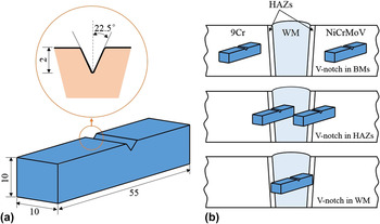
The Charpy V-notch (CVN) impact specimens were machined from the dissimilar welded joint with the notch roots located in BMs, HAZs, and WM, respectively. It should be noted that the V-notches in the WM are located at the middle of the WM. The method to remove the test specimens from the welded joint and the shape and size of the impact specimens are illustrated in Fig. 1. Before processing, the surface of welded joint was etched by dilute aqua regia to confirm the accurate locations of WM and HAZs. The Charpy impact tests were conducted on the pendulum impact tester (Zwick RKP450, Zwick, Ulm, Germany) according to the test standard ISO 148-1:2009 which is a standard test method for Charpy pendulum impact testing of metallic materials. During the test, the temperature range of the specimens was set from −60 °C to 60 °C (−60 °C, −40 °C, −20 °C, 0 °C, 20 °C, 40 °C, and 60 °C) to generate a complete absorbed energy curve that could be used to calculate the fracture appearance transition temperature (50% FATT) of WM. To maintain the testing temperature in each case, the specimens were kept in a thermostatic oven or in an insulated box filled with a mixed solution of high purity alcohol and liquid nitrogen, respectively. All of the specimens were kept at the temperature at which they were to be tested for approximately 15 min to maintain their thermal equilibrium. Considering the inhomogeneity of HAZs, nine specimens were machined in these zones to get more reliable data, while for WM and BMs, three or four specimens were prepared under each temperature to ascertain the repeatability of the test results.
The schematic welded joint and Charpy V-notch (CVN) impact specimen: (a) the shape and size of the Charpy V-notch impact specimen and (b) the method to remove the test specimens from the dissimilar welded joint.

D. Microstructure analysis
After impact test, all the specimens were cut into two parts, one of them was split along the middle of longitudinal direction to determine the accurate fracture locations, and another was used to observe the fracture morphology. In view of the strong corrosion resistance of 9Cr steel, dilute aqua regia made up of HCl + HNO3 + H2O with the proportion of 3:5:5 was selected as the etchant. Micro-hardness on the overall section of the welded joint was measured by a hardness tester (Zwick Roell Group, Ulm, Germany) with a constant load of 9.8 N for 15 s. In addition, optical microscope (OM; Zeiss Image A2m, Carl Zeiss AG, Oberkochen, Germany) and scanning electron microscope (SEM; JSM 7600F, JEOL, Ltd., Tokyo, Japan) were used to characterize the microstructure and the morphology of the fracture surface.
III. RESULTS AND DISCUSSION
A. Absorbed energy
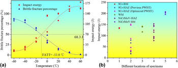
The CVN impact test, a standardized high-strain-rate impact test, determines the amount of energy absorbed during material fracture as well as the energy required to cause material fracture at operational temperature. Reference Sreenivasan25 The temperature-dependent absorbed energies for different locations are displayed in Fig. 2. As shown in Fig. 2(a), the absorbed energy for WM decreases gradually with the decreasing temperature, and there exists an upper shelf energy region (165.0 J, which starts at 60 °C), a lower shelf energy region (14.5 J, which starts at −60 °C), and a transition region. In the transition region, the fracture appearance transition temperature (50% FATT) is defined as the temperature where brittle fracture percentage reaches 50%, Reference Norris26 and the calculated 50% FATT for WM is −11.0 °C, corresponding absorbed energy is 68.3 J. It is known that the operating temperature should be greater than the 50% FATT for structural design purposes because brittle fracture can occur easily when the temperature is lower than the 50% FATT. Reference Chao, Ward and Sands11
Results of CVN impact tests: (a) the temperature-dependent absorbed energy and brittle fracture percentage for WM, and (b) absorbed energies for different locations at 20 °C. BM, WM and HAZ mean base metal, weld metal and heat affected zone, respectively.

Figure 2(b) illustrates a plot of the CVN absorbed energies for different locations at 20 °C. It is found that the NiCrMoV-BM exhibits higher absorbed energy levels (201.9 J), whereas the 9Cr-BM and WM exhibits relatively low absorbed energy levels (134.3 J and 132.7 J, respectively). In contrast to the BMs and WM, the absorbed energy for HAZs is especially scattered, as for NiCrMoV-HAZ, the maximum absorbed energy (153.2 J) is almost twice the minimum (77.9 J), and the average value is about 115.0 J. Furthermore, the lowest absorbed energy occurs in 9Cr-HAZ, and the specific absorbed energy for 9Cr-HAZ is listed in Table II, it can be seen that before the second step heat treatment, the minimum absorbed energy for 9Cr-HAZ is as low as 18.7 J, and the average value is 36.6 J. For this dissimilar welded joint, when the absorbed energy of any portion at room temperature is lower than 30 J or the 50% FATT is higher than 40 °C, it will not meet the requirements in practice due to its working condition. For this reason, the second step heat treatment (optimized PWHT) was carried out to improve the impact properties of 9Cr-HAZ. Consequently, the minimum and average absorbed energy for 9Cr-HAZ rise to 31.8 J and 83.0 J respectively, which could meet the requirements. This phenomenon is analyzed by investigating the microstructure and the fracture morphology, as described in the following section.
The specific absorbed energy for 9Cr-HAZ at different PWHT (J).

B. Microstructure characterization and micro-hardness test
As different microstructure determines different Charpy impact property in the 9Cr/NiCrMoV dissimilar welded joint, it is essential to characterize the details of the microstructure of the BMs, WM and HAZs.
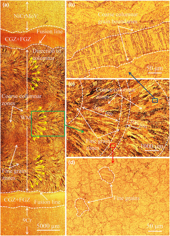
Figure 3 reveals the overall macrostructure of advanced 9Cr/NiCrMoV dissimilar welded joint manufactured by NG-SAW. It is clearly seen that the whole joint consists of five sections, i.e., NiCrMoV-BM, NiCrMoV-HAZ, WM, 9Cr-HAZ and 9Cr-BM, among which the width of WM made up of multi-layer and multi-pass structure is about 30 mm. The multi-layer structure of WM is further displayed in Fig. 3(c), it is observed that every layer includes coarse columnar and fine grain zone, and their average width is about 3 mm and 0.5 mm, respectively. The growth direction of the columnar grain is in the opposite direction of heat transfer which is indicated by the divergent arrows in Fig. 3(a), and the thermal cycle effect from next layer to previous layer results in the formation of fine grain zone which is regarded as the HAZ of the previous layer. The higher magnified OM images of columnar and fine grain are exhibited in Figs. 3(b) and 3(d), where the grain boundaries can be detected clearly. It can be seen that the columnar grain is in cast structure and the size can reach hundreds of micrometer, while the average diameter of fine grain is about 50 μm. Compared to BMs, this nonuniform microstructure made up of columnar and fine grains eventually results in relatively large variation of absorbed energy in WM [as shown in Fig. 2(a)].
Structure of the dissimilar welded joint for advanced 9Cr/NiCrMoV steels etched by HCl + HNO3 + H2O with the proportion of 3:5:5 for about 30 s: (a) the overall macrostructure of the whole dissimilar welded joint, (b) detailed microstructure of coarse columnar zone, (c) microstructure of the columnar zone and fine grain zone of WM, and (d) detailed microstructure of fine grain zone.

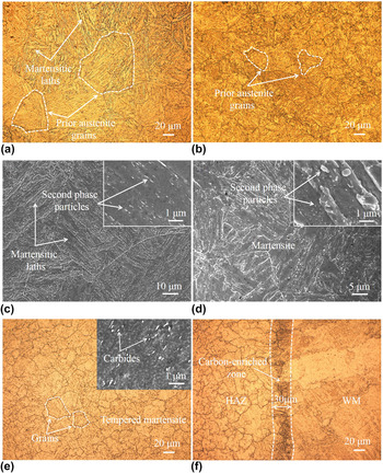
As shown in Figs. 4(a) and 4(b), the main microstructure of 9Cr-BM is tempered lath-martensite, while for NiCrMoV-BM, tempered martensite without typical lath structure is obtained, and its average grain size is smaller than that of 9Cr-BM. Figures 4(c) and 4(d) display the distribution of the second particles in 9Cr-BM and NiCrMoV-BM, it is worth noting that the second phase particles reveal a linear shape and mostly disperse along martensitic laths for 9Cr-BM in the inset of Fig. 4(c), while in the inset of Fig. 4(d), the second phase particles dispersively distribute in the matrix for NiCrMoV-BM.
Images to show the microstructure details of dissimilar base metals and 9Cr-HAZ: (a) OM image for advanced 9Cr, mainly contains tempered lath-martensite, (b) OM image for NiCrMoV, mainly contains tempered martensite but without typical lath structure, (c) SEM image for advanced 9Cr, (d) SEM image for NiCrMoV, (e) detailed microstructure of coarse grain zone for 9Cr-HAZ and (f) microstructure of carbon-enriched layer on the interface between 9Cr-HAZ and WM. The insets in (c), (d), and (e) reveal the size, shape, and distribution of second phase particles in 9Cr-BM, NiCrMoV-BM, and 9Cr-HAZ, respectively.

As is well-known, HAZ is significant for the reliability of the whole welded joint due to its complex microstructure resulted from the large temperature gradient from the weld to the base metal. Reference Zhu and Xuan27 9Cr-HAZ can be subdivided into coarse grain zone (CGZ) and fine grain zone (FGZ), and the image of coarse grains whose average diameter is about 30 μm are illustrated in Fig. 4(e). Besides, the microstructure of 9Cr-HAZ is mainly granular tempered martensite resulting from the fast-speed quenching process which further refines the grain and increases the carbon saturation of martensite during the welding process. In the inset of Fig. 4(e), the second phase particles of 9Cr-HAZ reveal a linear shape. It is worth noting that a 30 μm width carbon-enriched layer can be observed on the interface between 9Cr-HAZ and WM in Fig. 4(f). The formation of carbon-enriched layer attributes to the different content of Cr element in 9Cr-BM and WM, then carbon migration from WM to 9Cr-BM occurs during welding procedure. Reference Wu, Lu, Cui, Liu, Wang and Tang28 This carbon migration and the formation of carbon-enriched layer were considered as a crucial factor in high-cycle fatigue performance, Reference Wu, Lu, Cui, Liu, Wang and Gao29 and also deteriorated the impact properties of the welded joint in this study.
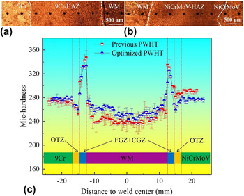
Vickers micro-hardness profiles over the whole dissimilar welded joints going through different PWHTs were conducted to compare the change of hardness value. As presented in Fig. 5(c), for previous PWHT joint, the average micro-hardness of NiCrMoV-BM is slightly higher than that of 9Cr-BM and WM which can be explained by the different microstructure possessed by these two kinds of BMs and WM (displayed in Figs. 3 and 4). In addition, a scattered micro-hardness in HAZs is observed which indicates that the properties of HAZs are nonuniform, which can be used to account for the scatter of absorbed energies in HAZs, and the corresponding locations of the micro-hardness measurement in HAZs are illustrated in Figs. 5(a) and 5(b). Additionally, there exists a hardness drop area called over tempered zone (OTZ) on each side of the welded joint, and over tempering during welding is the primary factor of the formation of OTZ.
Micro-hardness results: (a) and (b) the corresponding locations of the micro-hardness measurement in HAZs, (c) micro-hardness profile over the whole dissimilar welded joint of 9Cr/NiCrMoV going through different PWHTs. WM, FGZ, CGZ, and OTZ mean weld metal, fine grain zone, coarse grain zone, and over tempered zone, respectively.

After optimized PWHT, the average micro-hardness of WM rises about 15 HV, while it drops about 20 HV for NiCrMoV-BM, and this reduction in micro-hardness means the decrease in yield strength, because there is a positive correlation between yield strength and micro-hardness. Reference Ashrafizadeh and Eivani30,Reference Ceschini, Morri, Morri and Pivetti31 To satisfy the working conditions, NiCrMoV-BM must possess relatively high strength which restricts the temperature of PWHT. Based on the past data and experience, 620 °C ultimately was set as the optimized heat treatment temperature to improve the impact properties of 9Cr-HAZ without reducing the strength of NiCrMoV-BM too much. Going through this optimized PWHT, the peak hardness of 9Cr-HAZ decreases about 20 HV which is benefit for the improvement of impact toughness. In addition, there is no great change in micro-hardness of 9Cr-BM for its superior high temperature stability.
C. Fracture locations and microstructure evolution
In this section, the impact specimens in 9Cr-HAZ under different PWHT processes were split along the middle of longitudinal direction to determine the accurate V-notch locations and the crack growth paths.
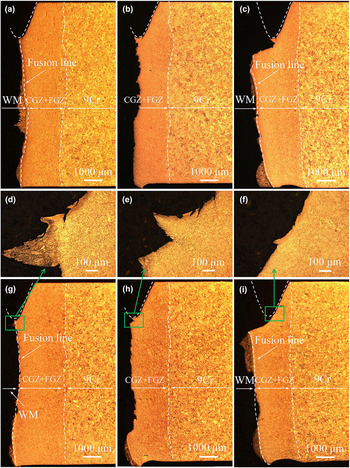
As shown in Fig. 6, the specimens of similar crack growth paths but under different heat treatment processes were selected to reveal the effect of optimized PWHT on the improvement of impact toughness. In Figs. 6(a)–6(c), the absorbed energies of the specimens under the previous PWHT are 18.9 J, 31.2 J, and 79.9 J respectively, which varies with the change of V-notch locations and the crack growth paths. Due to the microstructure complexity and narrow width of these zones, it is technically difficult to ensure bottom of every V-notch is at the same position. What is more, the absorbed energy mainly depends on the crack propagation process, during which the crack might go through CGZ, FGZ as well as the carbon-enriched layer as depicted in Fig. 6. In Fig. 6(a), the V-notch is located in carbon-enriched layer and the fracture path grows along the carbon-enriched layer well, which results in a very low absorbed energy. As displayed in Fig. 6(b), the V-notch is located in CGZ and fracture path also grows along the V-notch well. It is worth noting that when the V-notch location changes to FGZ [Fig. 6(c)], there exists a deflection from FGZ to carbon-enriched layer on the crack growth path which indicates that the carbon-enriched layer is the weak part of HAZ in Charpy impact experiment, but this deflection needs to consume plenty of energy during the process of impact and leads to the promotion of absorbed energy.
Confirmed fracture locations of different specimens in 9Cr-HAZ: (a) impact energy is 18.9 J, the fracture path is along the carbon-enriched layer, (b) impact energy is 31.2 J, the fracture path is located in CGZ, (c) impact energy is 79.9 J, the fracture path is along the carbon-enriched layer but the V-notch is located in FGZ, (g) impact energy is 33.8 J, the fracture path is similar to (a), (h) impact energy is 46.5 J, the fracture path is similar to (b), (i) impact energy is 87.0 J, the fracture path and V-notch location is similar to (c), and (d)–(f) are the magnified images of the fracture initiation area of (g)–(i). Additionally, specimens of (a)–(c) and (g)–(i) go through the previous and optimized PWHT process respectively.

After optimized PWHT, the similar V-notch locations and crack growth paths are observed in Figs. 6(g)–6(i), and the absorbed energies rise to 33.8 J, 46.5 J, and 87.0 J respectively. Compared to Figs. 6(a)–6(c), the absorbed energies are promoted by 79%, 49%, and 9% respectively in Figs. 6(g)–6(i), and this different proportion is related to the different V-notch locations and fracture paths. When the V-notch is located in carbon-enriched layer in Figs. 6(a) and 6(g), the absorbed energy is mainly determined by the microstructure of carbon-enriched layer which was effectively improved by optimized PWHT, resulting in the great promotion of absorbed energy, whereas the influence of microstructure improvement on the promotion of absorbed energy is not obvious when there exists a deflection on the crack growth path in Figs. 6(c) and 6(i). In addition, the magnified images of the fracture initiation area are displayed in Figs. 6(d)–6(f).
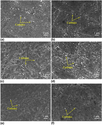
Figure 7 presents the SEM images of the microstructure near the fracture in 9Cr-HAZ including CGZ [Figs. 7(a) and 7(b)], carbon-enriched layer [Figs. 7(c) and 7(d)] and carbon-depleted zone [Figs. 7(e) and 7(f)] under different PWHT conditions to reveal the evolution of microstructure. The previous and optimized PWHT microstructure are shown in Figs. 7(a), 7(c), 7(e) and Figs. 7(b), 7(d), 7(f) respectively. Martensitic laths with banded carbides distributed along the laths can be detected in Figs. 7(a) and 7(c), while nonlath martensitic matrix as well as massive ellipsoidal carbides is found in Figs. 7(b) and 7(d). Compared to previous PWHT metals, the carbides obviously grow up in Figs. 7(b) and 7(d) which indicates that the supersaturated carbon has partially precipitated from the matrix, and this transform of matrix structures and carbides eventually reduced the micro-hardness of 9Cr-HAZ as presented in Fig. 5(c). Additionally, carbides increase slightly in carbon-depleted zone as it is shown in Figs. 7(e) and 7(f). It can be concluded that the microstructure evolution from martensitic laths in the previous PWHT metals to a softer ferrite matrix with the supersaturated carbon precipitating from the matrix led to higher toughness in the optimized PWHT materials.
The microstructure evolution of 9Cr-HAZ under different PWHTs: (a) microstructure of CGZ under previous PWHT, (b) microstructure of CGZ under optimized PWHT, (c) microstructure of carbon-enriched zone under previous PWHT, (d) microstructure of carbon-enriched zone under optimized PWHT, (e) microstructure of carbon-depleted zone in WM under previous PWHT and (f) microstructure of carbon-depleted zone in WM under optimized PWHT.

D. Fracture morphology
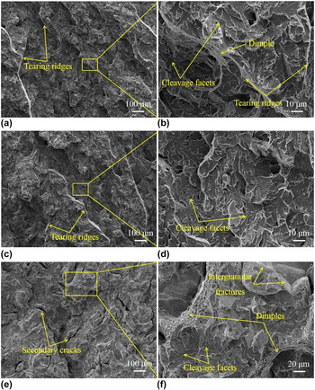
The fracture morphology of specimens notched in 9Cr-HAZ was characterized by SEM to evaluate the fracture mode. Figure 8 illustrates the fractography of the Charpy specimens under previous PWHT condition. As shown in Figs. 8(a) and 8(b), the quasicleavage surfaces and dimpled-tearing ridges, which are taken as typical brittle fracture features, could be seen on fracture surfaces, and this characteristics of brittle fracture is consistent with its low absorbed energy (18.9 J). In Figs. 8(c) and 8(d), it is observed that the fracture is also quasicleavage fracture which is characterized by abundant river patterns, and the impact energy is 31.2 J, while in Figs. 8(e) and 8(f), cleavage facets and intergranular fractures as well as dimples are observed, and it is worth noting that there exists massive secondary cracks on the surface which is benefit for the improvement of absorbed energy (79.9 J). Through the observation of the fracture morphology of 9Cr-HAZ, it can be concluded that the fractography varied from brittle fracture to a fracture mode with both brittle and ductile fracture feature with the change of crack growth paths.
The fractography of the Charpy specimens in 9Cr-HAZ under previous PWHT condition with different fracture paths: (a) and (b) impact energy is 18.9 J and the fracture path is along the carbon-enriched layer, (c) and (d) impact energy is 31.2 J and the fracture path is located in CGZ, (e) and (f) impact energy is 79.9 J, the fracture path is along the carbon-enriched layer but the V-notch is located in FGZ.

IV. CONCLUSIONS
The impact toughness and related microstructure of 9Cr/NiCrMoV dissimilar welded joint fabricated by narrow-gap submerged arc welding (NG-SAW) via multi-layer and multi-pass technology were systematically investigated in this paper, especially focusing on the weakest zone in toughness of the whole welded joint, the main conclusions can be drawn as follows:
-
(1) Results of temperature-dependent absorbed energy indicated that the fracture appearance transition temperature (50% FATT) for weld metal (WM) was −11 °C, and the corresponding absorbed energy was 68.3 J.
-
(2) 9Cr-HAZ with low and scattered absorbed energies determined by different crack growth paths at 20 °C was found to be the weakest zone of the welded joint which could not satisfy the requirement. Fracture path observation found that the weakening of 9Cr-HAZ is related to the carbon-rich layer near the fusion line, and the impact energy of the fracture along the carbon-rich layer is the lowest. By the means of optimizing the postweld heat treatment (PWHT) process, a dramatically enhanced impact toughness for 9Cr-HAZ was obtained to meet the demand.
-
(3) Characterization of the microstructure revealed that the microstructure evolution from martensitic laths in the previous PWHT metals to a softer ferrite matrix with the supersaturated carbon precipitating from the matrix led to higher toughness in the optimized PWHT materials.