I. INTRODUCTION
Laser additive manufacturing (LAM) involves a group of advanced technologies used for preparing net-shaped intricate parts through the computer-aided design model.Reference Gu, Wang, Dai, Chang, Meiners, Hagedorn, Wissenbach, Kelbassa and Poprawe1–Reference Attar, Bonisch, Calin, Zhang, Zhuravleva, Funk, Scudino, Yang and Eckert4 LAM processes were initially proposed for fabricating prototypes but in a few decades, their use changed and nowadays they are also exploited for preparation of structural or functional components for service in industrial and medical applications.Reference Gu and Shen5–Reference Ma, Gu, Dai, Chen, Chang, Yuan and Shen7 One LAM technique that has attained considerably rising attention and engagement by industrial manufacturers is selective laser melting (SLM), which is based on local melting of a metal powder bed by using a high power laser beam.Reference Simonelli, Tse and Tuck8–Reference Jagle, Choi, Van Humbeeck and Raabe10 In comparison to the traditional manufacturing technologies, finer microstructures can be obtained in the SLM-processed parts due to the very high cooling rate of the melt pool.Reference Raghavan, Wei, Palmer and DebRoy11 Excellent mechanical properties can be achieved derived from the significant grain refinement strengthening. Therefore, SLM shows a great potential in a broad range of industrial sectors, including aerospace, biomedical science, and automotive industries.Reference Chen, Gu, Xiong and Xia12
Until now, SLM has been proved to be applicable in a number of alloy systems: 316L steel,Reference Sun, Moroz and Alrbaey13 CoCrMo,Reference Chen, Phan and Darvish14 Ti6Al4V,Reference Thijs, Montero, Maria, Wauthle, Xie, Kruth and Van Humbeeck15 18Ni300,Reference Tan, Zhou, Ma, Zhang, Liu and Kuang16 IN718,Reference Amato, Gaytan, Murr, Martinez, Shindo, Hernandez, Collins and Medina17 pure Ti,Reference Gu, Hagedorn, Meiners, Meng, Batista, Wissenbach and Poprawe18 etc. These materials possess appropriate thermal physics properties, such as high enough laser absorptivity and suitable thermal conductivity, for laser processing and hence exhibit a good SLM processability. However, for aluminum alloys, like AlSi12, due to the limited absorption caused by the high reflectivity of laser energy and rapid dissipation of heat loss because of the high thermal conductivity, some phenomena such as defects of adherent oxidation films and internal pores have a high tendency to form during SLM aluminum alloys.Reference Gu and Dai19 To get rid of these problems, aluminum alloys are typically fabricated using high laser powers combined with low laser scanning speeds, ensuring the full melting and the resultant efficient spreading of the melt.Reference Gu, Meiners, Wissenbach and Poprawe20 However, a large energy input always brings about overheating phenomenon and vigorous melt flow behavior, hence resulting in a limited SLM processability of aluminum alloys. Therefore, it is of great significance to find the method to improve the stability of the SLM process of the aluminum parts produced by SLM without varying the set energy input. In the SLM process, the hatch style of the laser beam highly influences the heat dissipation mode, thus playing a significant role in densification behavior, microstructure, and resulting mechanical property of SLM-processed parts. The appropriate scanning strategy gave an appreciable reduction in metallurgical defects and thermal deformations, and the beneficial effect of vaporization to restrain the balling effect was observed.Reference Kruth, Froyen, Van, Mercelis, Rombouts and Lauwers21 Based on the above reasons, changing laser hatch style to improve SLM processability of aluminum alloys is a very significant research approach.
The objective of this study is to analyze the effect of different laser hatch styles [single fill (SF), cross fill (CF), and checker board (CB)] on the SLM process stability, microstructure evolution, and the resulting wear resistance performance. The various heat dissipation modes under different laser melting sequences were discussed to reveal the mechanism of defect formation, microstructural heterogeneity, and failure behavior in sliding wear test. The metallurgy process and rheological behavior of the melt were studied in detail, to reveal the main features of the trapped pores and their formation mechanism under high-speed laser scanning. A good surface quality is critical in many applications, because a better surface quality can avoid the formation of surface-initiated cracking and, an excellent wear resistance is of great help for improving the working life of parts. So, it is greatly meaningful to make an in-depth research about the geometric accuracy and wear performance of SLM-processed parts. These investigations provide a significant insight into the SLM process and contribute to the fabrication of high performance aluminum parts with a short production period, to meet some specific requirements of the rapid tooling, biomedical, and aerospace sectors.
II. EXPERIMENT
A. Powder material
Gas-atomized AlSi12 powder was exploited in this study; the chemical compositions were 87.5 wt% Al, 12.3 wt% Si, 0.1 wt% Fe, and 0.05 wt% Mg. The powder had a spherical shape (Fig. 1) and the range of particle size of the powder material was 20–63 μm with an average diameter of 33 μm.
Particle morphology of original powder.

B. SLM process
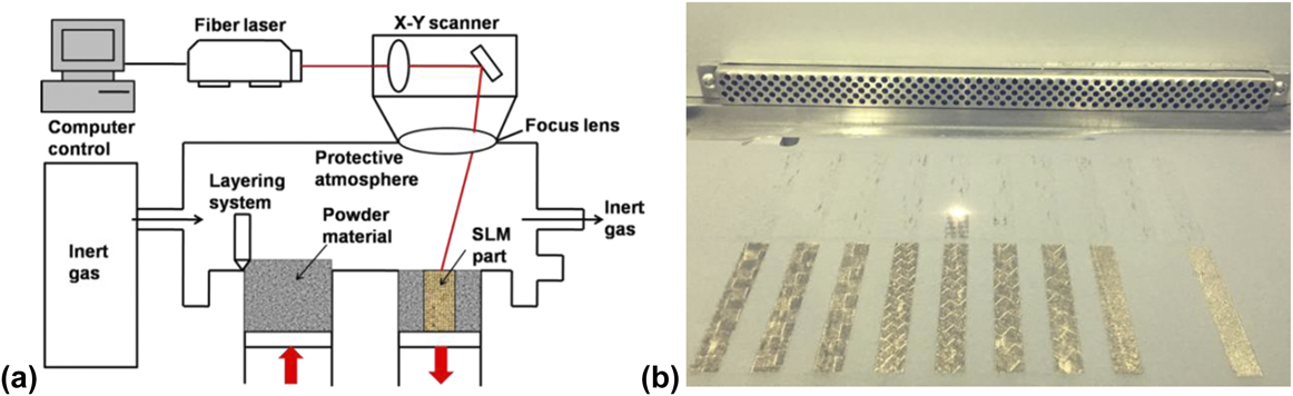
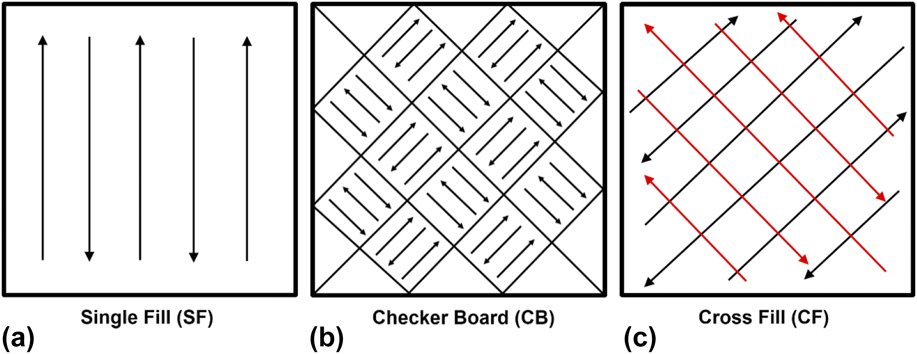
The SLM machine mainly consists of IPG YLR-500 ytterbium fiber laser with the maximum power of ∼500 W (IPG Laser GmbH, Burbach, Germany), the diameter of the spot of 70 μm, the wavelength of 1.06 μm, an automatic system for powder delivery, and a computer system for process control. The focal length of laser beam is automatically changed to ensure that the diameter of the spot keeps the same value in different locations of the substrate. In order to avoid oxidation of the aluminum alloy, the SLM process proceeded under high vacuum conditions where oxygen content below 20 ppm. When the specimens were to be prepared, an aluminum substrate was fixed on the building platform and leveled, with dimensions of 150 × 150 × 30 mm. The schematic of the SLM process is shown in Fig. 2(a). To investigate the effect of the laser hatch style on the SLM processing quality, different scan patterns were conducted in the SLM process (Fig. 3): SF-laser beam scans the powder bed once and all the scan tracks were oriented parallel to each other; CF-laser beam scans the powder bed twice and after the first melting sequence, a second sequence took place along the same layer with 90° scan rotation to remelt the solidified layer; CB-the same layer was divided into numerous small islands and laser melted these islands in the designed sequence. Cuboidal specimens of size 10 × 10 × 5 mm with a layer thickness of 30 μm were produced on the aluminum base plate using different laser hatch styles. Hatch spacing was 60 μm to assure sound overlap between tracks. Based on a series of preliminary experiments, the laser power (P) and the scan speeds (v) were optimized at 450 W and 3500 mm/s to obtain a good SLM processability without macroscopic balling phenomenon and dimensional distortion [Fig. 2(b)].
(a) Schematic of the SLM apparatus and (b) the real time interaction of the laser beam and the powder material.

SLM processing AlSi12 parts using different laser hatch styles: (a) SF; (b) CB; (c) CF.

C. Microstructural characterization
The samples for metallographic examinations were cut, ground, and polished according to standard procedures and etched with a solution consisting of solution comprising HF (2 mL), HCl (3 mL), HNO3 (5 mL), and distilled water (190 mL) for 10 s. Microstructures were characterized using a PMG3 optical microscope (OM; Olympus Corporation, Tokyo, Japan) and a S-4800 field emission SEM (FE-SEM; Hitachi Corp., Tokyo, Japan) at 3 kV. The variation of melt pool dimensions under different laser hatch styles was obtained by measuring its length, width, and depth in the OM. At least 20 melt pools were investigated and the mean dimensions of melt pool were calculated.
D. Mechanical property tests
The Archimedes principle was used to measure the relative density of the specimens. The Vickers hardness was measured using a MicroMet 5101 microhardness tester (Bühler GmbH, Braunschweig, Germany) at a load of 0.1 kg and an indentation time of 20 s. The tribological property of the specimens was estimated by the dry sliding wear tests conducted on a HT-500 ball-on-disk tribometer (Lanzhou ZhongKe KaiHua Sci. & Technol. Co., Ltd., Lanzhou, China) in air at room temperature. The counter material was GCr15 bearing steel ball with a diameter of 3 mm and a mean hardness of HRC60, using a test load of 3 N. The friction unit was rotated at a speed of 560 rpm for 15 min, with the rotation radius of 2 mm. The coefficient of friction (COF) of the specimens was recorded during wear tests. The wear volume (V) was determined gravimetrically using the following equation:
 $$V = {{{M_{{\rm{loss}}}}} \over \rho }\quad ,$$
where M loss is the weight loss of the specimens. The wear rate (ω) was calculated by
 $$\omega = {V \over {WL}}\quad ,$$
where W is the contact load and L is the sliding distance.
III. RESULTS AND DISCUSSION
A. Densification behavior
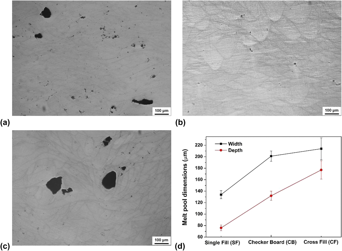
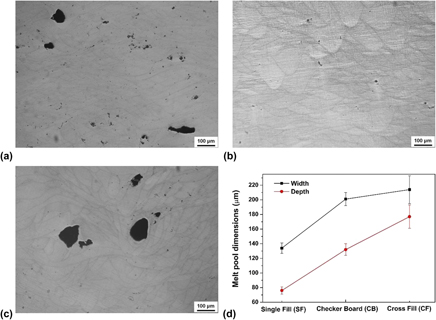
It is essential to comprehensively study the metallurgical defects and corresponding densification behavior of SLM-processed parts due to their important effect on the performance of the SLM parts. The microstructures and corresponding melt pool dimension obtained using various laser hatch styles are shown in Fig. 4. Figure 5 shows the calculated relative density by the Archimedes method under different laser hatch styles. With the SF employed, some micropores with a mean size of around 50 μm were observed from the cross section [Fig. 4(a)]. The average dimensions of width and depth of melt pool were estimated to be 134 μm and 76 μm, respectively [Fig. 4(d)], and in this situation, the densification rate was restricted by 98.15% theoretical density (TD) (Fig. 5). As the hatch style was changed to CB, metallurgical defects were effectively eliminated and the cross section of the SLM part became denser without obvious pores [Fig. 4(b)]. The melt pools were observed to possess a larger dimension with an average width of 201 μm and depth of 132 μm. The densification level increased to 99.42% TD (Fig. 5). When using the CF style, relatively large round or subround pores emerged on the cross section with a mean size of about 100 μm [Fig. 4(c)], reducing the densification rate to 96.31% TD [Fig. 4(c)] in this situation. Distinctively, the melt pool distribution obtained by the CF style exhibited an extremely irregular and disordered feature, e.g., the fluctuation of melt pool dimensions was significantly larger in comparison to SF and CB. The melt pools with a larger average width of 214 μm and depth of 177 μm were attained, revealing the important role of laser melting process in the melt pool dimension.
OM images showing characteristic microstructures on cross section of SLM-processed parts at (a) SF; (b) CB; (c) CF. (d) Variation of melt pool dimension under different laser hatch styles.

Variation of densification level of SLM-processed parts with different laser hatch styles.

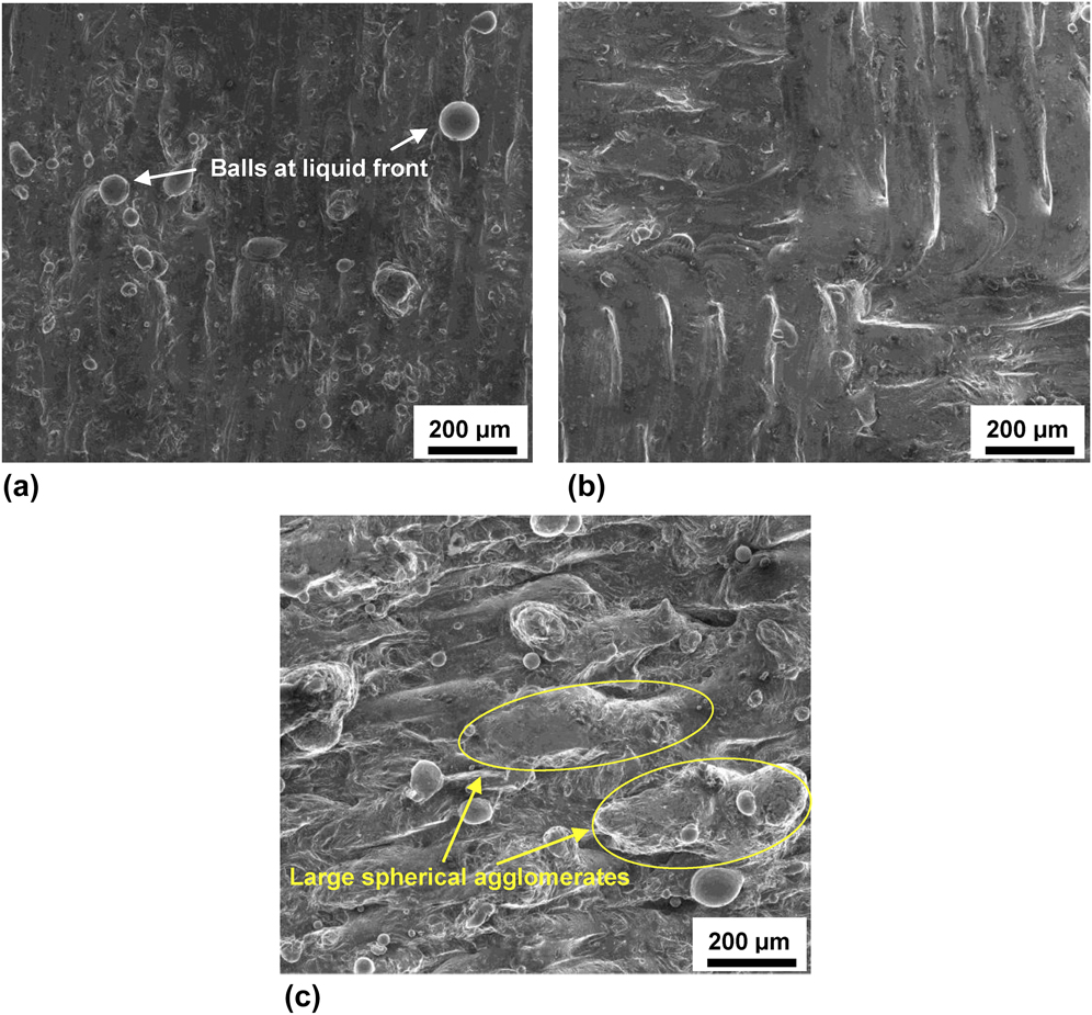
The different line-by-line laser scanning sequence brought by different laser hatch styles can lead to various heat dissipation modes of the melt pool, hence resulting different thermal histories and solidification processes of SLM. Thus, it is undoubted that laser hatch styles have a great influence on the densification level and the continuity of the resultant solidified microstructure of SLM-processed parts. The morphology of the top surface of the SLM-processed parts can exhibit the processing quality of SLM perfectly. Therefore, the typical surface morphology of the SLM-processed parts under different hatch styles and corresponding measured surface roughness is given in Fig. 6. It could be found that the prominent spatter phenomenon occurred during the SLM process when using the SF style. A large number of metallic balls on a scale of ∼120 μm formed on the top surface of the specimen [Fig. 6(a)]. These metallic balls severely hindered the even deposition of the fresh powder on the previously solidified layer,Reference Chen and Gu22 thus giving rise to interlayer pores and a limited densification level of 96.31% TD. Spatter is a common phenomenon during SLM processing aluminum alloy since a high laser power combined with a low laser scanning speed (a large laser energy density) is generally used. As the melt pool forms with full liquid, the dynamic viscosity μ of the melt can be evaluated byReference Gu, Hagedorn, Meiners, Wissenbach and Poprawe23
 $$\mu = {{16} \over {15}}\sqrt {{m \over {{k_{\rm{B}}}T}}} \gamma \quad ,$$
where m is the atomic mass, k B is the Boltzmann constant, T is the temperature of the molten pool, and γ is the surface tension of the melt. A large laser energy density imposes excessive energy on the melt pool and enhances the T significantly. Based on Eq. (3), a high T decreases the dynamic viscosity μ within the pool, thus increasing melt flow ability and resulting in a higher level of overheating of the melt. Moreover, the steep temperature gradient between the center and boundary of the melt pool produces significant surface tension gradients and attendant Marangoni flow.Reference Simchi24 Due to the formation of intensive streams within the melt pool, liquid droplets have a high tendency to splash from the liquid front, thus causing several small-sized metallic balls generated on the SLM-processed surface. The splash phenomenon was considerably alleviated as the hatch style changed to CB. A clear and regular liquid solidification front free of any balling phenomenon was observed, yielding stable and continuous scan tracks [Fig. 6(b)]. The scans with CB style of shorter scan length leave much better solidification tracks since the shorter scan lengths between the adjacent scanning leave little time for the substrate to cool down,Reference Suryawanshi, Prashanth, Scudino, Eckert, Prakash and Ramamurty25 which results in lower temperature gradient in small areas compared with SF style. According to Arafune and Hirata’s results,Reference Arafune and Hirata26 the dimensionless Marangoni number (M a) can be used to estimate the intensity of Marangoni flow:
 $${M_{\rm{a}}} = {{\Delta \sigma L} \over {\mu {v_{\rm K}}}}\quad ,$$
where Δσ is the surface tension difference of Marangoni flow, L is the length of the free surface, μ is the dynamic viscosity, and v K is the kinematic viscosity. A reduced temperature gradient can lead to decreased surface tension variation Δσ, thus resulting in a weaker Marangoni flow within the melt pool. Therefore, The CB style can improve the stability of the melt pool and alleviate splash phenomenon, hence enhancing the surface quality and densification level of SLM-processed parts. Due to the reduced heat dissipation rate when using CB style, the dimension of the melt pool shows an increasing trend compared with the SF style. The CF style brought unfavorable surface quality to SLM-processed parts as shown in Fig. 6(c), showing the significant effect of the laser remelting process on the surface morphology of the aluminum alloy. Laser remelting every layer involves a large heat dissipation rate because the solid material has a higher heat conductivity than the powder material. The reduced amount of liquid formation and rheological property of the melt pool increase the instability of melt. In order to reach the equilibrium state, the instable melting track breaks up into several spherical agglomerates, which is referred to “balling” effect.Reference Li, Liu, Shi, Wang and Jiang27 The prominent “balling” effect dramatically deteriorates the processing quality of SLM, hence resulting in relatively large round or subround pores emerged in the SLM-processed parts. Furthermore, the extra thermal brought by the remelting process can also induce the tempering effect, which may cause the merging and growing of melt pools and recrystallization of grains. Thus, an extremely irregular and disordered configuration of the melt pool with a large fluctuation in dimensions could be observed in this situation.
FE-SEM showing typical surface morphology of SLM-processed parts under (a) SF, (b) CB, and (c) CF hatch styles.

B. Microstructure
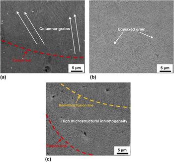
The FE-SEM images showing the microstructure evolutions of the SLM-processed aluminum part using different laser hatch styles are shown in Fig. 7. The specimen processed by SF style revealed a columnar solidification mode, with the phase contrast of white for the Si phase and grey for the Al-rich α-Al phase. The eutectic Si precipitated along the grain boundary during the rapid solidification process and then exhibited a columnar shape. The relatively coarse grain formed in the heat-affected zone (HAZ) and thus, the fusion line (melt pool boundary line) was visible as indicated by the red dotted line in Fig. 7(a). It could be found that the solidification within the melt pool occurred epitaxially at the partially melted grains lying along the melt pool boundaries. Interestingly, the columnar grains were not strictly developed along the normal direction of the melt pool boundary, which is generally the maximum thermal gradient and heat flux direction. It can be deduced that the grain development of aluminum during SLM should be determined by preferred crystallographic orientation of grain growth and thermal conditions simultaneously.Reference Wang, Song, Yang and Bai28 Using a CB style can significantly change the thermal history during SLM and modify the morphology of grain growth. It could be observed that the characteristic ring-shaped Si network morphology emerged in the most region of the melt pool, revealing the equiaxed development behavior of crystals [Fig. 7(b)]. The scans with CB style of shorter scan length left finer equiaxed grains to the solidification microstructure. The shorter scan lengths between the adjacent scanning leave little time for the base plate to cool down, hence imposing a great effect on the thermodynamics of crystallization. During CB scanning, adjacent tracks are scanned rapidly one after another in the small checker region, leaving little time for the heat to dissipate from the processing region to the substrate, thus resulting in the overheating effect lasting for some time. When the laser beam moved to another checker region, due to the large temperature difference between the high-temperature melt and low-temperature substrate, a higher undercooling degree can be obtained in small areas compared with other longer scan lengths. The thermodynamics nucleation rate N 1 mainly influenced by the variation of free energy of the system can be calculated byReference Chen, Gu, Xiong and Xia12
 $$N = K\exp \left( { - {{\Delta {G^{\rm{*}}}} \over {T\Delta {T^2}}}} \right)\quad ,$$
where K is a constant, ΔG* is the critical nucleation Gibbs free energy, T is the operative temperature, and ΔT is the undercooling degree. Equation (4) indicates that increased T and ΔT in the melt pool can dramatically elevate N, hence leading to refined equiaxed grains in the SLM part by CB style. The sample fabricated by CF style exhibited an appreciably different microstructure compared with the SF and CB parts. The remelting process proceeding after the current layer solidifies can bring more HAZ, hence increasing the microstructural inhomogeneity of SLM parts as shown in Fig. 7(c). More fusion lines (including melt pool fusion line and remelting fusion line) can be observed, leading to the increase of coarse grains zones in the SLM part. Coarse grains could be observed to prevail in HAZ and the grain size is several times as big as the original grains. Meanwhile, as reported by Wen et al.’s study,Reference Wen, Li, Wei, Yan, Zhang and Shi29 the nonmetallic elements, such as Si, C, and O, in the HAZ are generally in an unstable state. Therefore, the increase of the HAZ induced by conducting CF style is believed to be harmful to the mechanical property of SLM parts.
FE-SEM images showing the microstructure evolutions of SLM-processed parts under different laser hatch styles: (a) SF; (b) CB; (c) CF.

C. Hardness and tribological performance
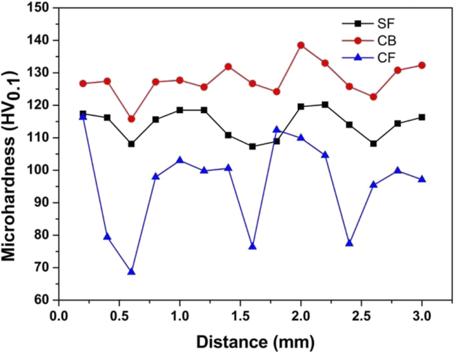
Generally, the densification level and microstructures determine the microhardness of the SLM-processed parts. Due to the inherent features of rapid heating and cooling, the microstructure of the SLM-processed parts shows a significantly ultrafine feature and the microhardness is higher than the components fabricated by the conventional process.Reference Gu, Hagedorn, Meiners, Wissenbach and Poprawe23 Figure 8 depicts the effect of laser hatch style on the microhardness and its distribution of the SLM-processed aluminum parts. The microhardness of the SLM part fabricated via SF style varied in a range from 107.3 HV0.1 to 120.2 HV0.1, and the average value was 114.3 HV0.1, showing the same level with the previously published value.Reference Olakanmi, Cochrane and Dalgarno30 As the CB was utilized for SLM, the microhardness varied from 115.8 HV0.1 to 138.5 HV0.1 and an enhanced mean microhardness of 129.7 HV0.1 was obtained. As the ring-like structure of Si particles become refined, the grain size of the Al matrix decreases and, accordingly, the grain refinement strengthening effect becomes more significant, which means that the SLM-processed part can withstand the load and indentation more effectively. For the SLM-processed aluminum part using CF style, the mean microhardness of the part decreased remarkably to 95.9 HV0.1 accompanied with a relatively large fluctuation with the change of the measurement positions. This was mainly attributed to the inhomogeneous distribution of the Si particle throughout the matrix.Reference Prashanth, Scudino and Eckert31 Besides, the densification level is also an important influencing factor on the hardness of the SLM-processed parts because the relatively low density of the SLM-processed aluminum part accompanied with the presence of the residual pores, especially the large-sized pore with a size of about 100 μm, is likely to underneath the indentations during the microhardness test, hence resulting in a poor load resistance of SLM parts.
Microhardness and its distribution of SLM-processed aluminum parts using different laser hatch styles.

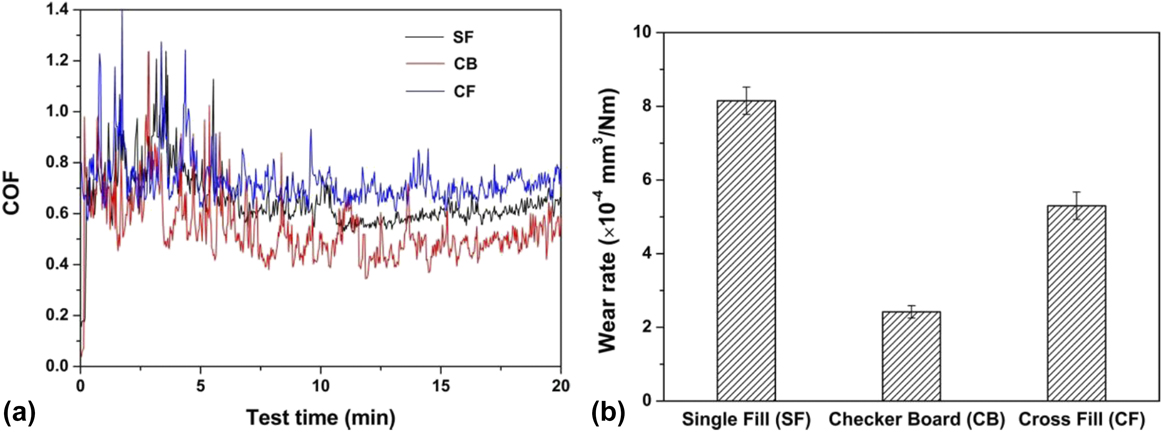
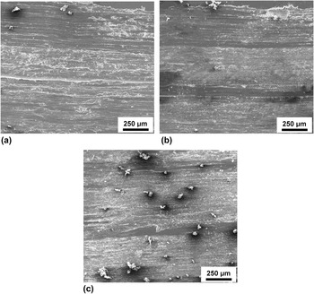
Figure 9 shows the effect of laser hatch style on COFs and wear rates of SLM-processed aluminum parts and the corresponding worn surfaces were also revealed by FE-SEM and given in Fig. 10. At the beginning of the wear tests, owing to the presence of adherent oxidation films on the surface of testing samples, the COF values were relatively high and fluctuated in a relatively large range. The oxide film could be broken easily and shifted by the direct sliding with the counterface after which the COF values gradually decreased and reached a relatively steady-state with reduced local fluctuation.Reference Gu, Wang, Dai, Chang, Meiners, Hagedorn, Wissenbach, Kelbassa and Poprawe1 From Fig. 9, it can be found that the large variations in COF values and attendant wear rates under different laser hatch styles demonstrated that the tribological performance of SLM-processed aluminum parts was dramatically affected by the applied laser scanning sequences. As the SF style was used, the parallel, deep grooves with rough edges were observed on the worn surface [Fig. 10(a)], representing typical abrasion wear. The worn surface was considerably rough and in this case, the average COF value and wear rate were detected at 0.61 and 5.37 × 10⁻⁴ mm3/(N m), respectively (Fig. 9). As the hatch style changed to CB, the worn surface of the SLM-processed part became rather smooth and the adhesive tribolayer can be found as shown in Fig. 10(b). The lowest COF of 0.49 [Fig. 9(a)] and wear rate of 2.43 × 10⁻⁴ mm3/(N m) [Fig. 9(b)] were obtained in this instance. It was accordingly reasonable to consider that the refined Si particles with a ring-shaped dispersion state formed in CB parts can significantly improve the wear resistance and change the mechanism of material removal during sliding from the abrasion to adhesion of the tribolayer. Such a transformation of the wear mechanism was supposed to reduce the COF values and the wear rate simultaneously after sliding tests. The average COF reached the highest value of 0.72 [Fig. 9(a)] when the CF style was conducted, giving rise to a considerably large wear rate of 8.22 × 10⁻⁴ mm3/(N m) [Fig. 9(b)]. In this case, the wear surface was disruptive and consisted of large-sized debris which peeled off during the sliding [Fig. 10(c)]. The presence of irregular shaped fragments revealed the local severe deformation and plowing of the worn surface occurred. The limited wear performance is mainly derived from the high porosity rate and poor microstructural homogeneity in this instance. The high porosity rate is associated with premature failure which is always initiated in residual pores and do harm to the wear performance. The microstructural inhomogeneity is due to the increase of the HAZ in the CF part as demonstrated before. The HAZ generally possesses worse properties compared with other regions of SLM parts. Therefore, fracture has a high tendency to originate at the HAZ and propagate from the HAZ to the melt pool zone when subjected to large friction during sliding.
COF values (a) and wear rates (b) of SLM-processed aluminum parts with variation of laser hatch styles.

FE-SEM images showing characteristic morphologies of worn surfaces of SLM-processed parts using various laser hatch styles: (a) SF; (b) CB; (c) CF.

IV. CONCLUSIONS
(1) The metallurgical defect and according densification level of SLM parts were significantly influenced by the laser hatch style. With the SF employed, some micropores were observed from the cross section, which were with a mean size of around 50 μm, and in this situation, the densification rate was restricted by 98.15% TD. When using the CF style, the melt pool distribution exhibited an extremely irregular and disordered feature. Relatively large round or subround pores emerged on the cross section with a mean size of about 100 μm, reducing the densification rate to 96.31% TD in this situation. As the hatch style was changed to CB, the stability of the melt pool was improved and the splash phenomenon was alleviated, hence eliminating metallurgical defects effectively. The cross section of the SLM part became denser without obvious pores (99.42%).
(2) The specimen processed by the SF style revealed a columnar solidification mode. The eutectic Si precipitated along the grain boundary during the rapid solidification process and then exhibited a columnar shape. Using a CB style can significantly change the thermal history during SLM and modify the morphology of grain growth. The characteristic ring-shaped Si network morphology emerged in the most region of the melt pool, revealing the equiaxed development behavior of crystals. The CF sample exhibited an appreciably different microstructure compared with the SF and CB parts. The remelting process proceeding after the current layer solidifies could bring more HAZ to the SF part, hence increasing the microstructural inhomogeneity of SLM parts.
(3) As the CB was utilized for SLM, the microhardness varied from 115.8 HV0.1 to 138.5 HV0.1 and an enhanced mean microhardness of 129.7 HV0.1 was obtained. The worn surface of the CB part was rather smooth and the adhesive tribolayer can be observed. The lowest COF of 0.49 and wear rate of 2.43 × 10⁻⁴ mm3/(N m) were obtained in this instance. The improvement of wear performance was mainly due to the enhancement of densification level and formation of refined equiaxed grain and evenly distributed ring-shaped Si particles formed in CB parts.
ACKNOWLEDGMENTS
The work was financially supported by the National Natural Science Foundation of China (Grant No. 51405082), the Natural Science Foundation of Guangdong Province (Grant No. 2014A030310301), and the Science and Technology Innovation Platform of Foshan City, Guangdong Province, China. (Grant No. 2016AG100341).