




No CrossRef data available.
Article contents
- Abstract
- 1. INTRODUCTION
- 2. PRODUCT DOCUMENTATION FOR DAIMLERCHRYSLER'S MERCEDES LINES
- 3. FORMALIZATION OF THE DOCUMENTATION SYSTEM
- 4. MAINTENANCE AND VALIDATION ISSUES
- 5. MANAGEMENT OF CHANGE
- 6. A SAT CHECKER FOR PRODUCT CONFIGURATION
- 7. BIS SOFTWARE ARCHITECTURE
- 8. INDUSTRIAL EXPERIENCE
- 9. RELATED WORK
- 10. CONCLUSIONS
- ACKNOWLEDGMENTS
- References
Formal methods for the validation of automotive product configuration data
Published online by Cambridge University Press: 07 August 2003
Article contents
- Abstract
- 1. INTRODUCTION
- 2. PRODUCT DOCUMENTATION FOR DAIMLERCHRYSLER'S MERCEDES LINES
- 3. FORMALIZATION OF THE DOCUMENTATION SYSTEM
- 4. MAINTENANCE AND VALIDATION ISSUES
- 5. MANAGEMENT OF CHANGE
- 6. A SAT CHECKER FOR PRODUCT CONFIGURATION
- 7. BIS SOFTWARE ARCHITECTURE
- 8. INDUSTRIAL EXPERIENCE
- 9. RELATED WORK
- 10. CONCLUSIONS
- ACKNOWLEDGMENTS
- References
Abstract
In the automotive industry, the compilation and maintenance of correct product configuration data is a complex task. Our work shows how formal methods can be applied to the validation of such business critical data. Our consistency support tool BIS works on an existing database of Boolean constraints expressing valid configurations and their transformation into manufacturable products. Using a specially modified satisfiability checker with an explanation component, BIS can detect inconsistencies in the constraints set and thus help increase the quality of the product data. BIS also supports manufacturing decisions by calculating the implications of product or production environment changes on the set of required parts. In this paper, we give a comprehensive account of BIS: the formalization of the business processes underlying its construction, the modifications of satisfiability-checking technology we found necessary in this context, and the software technology used to package the product as a client–server information system.
Information
- Type
- Research Article
- Information
- Copyright
- © 2003 Cambridge University Press
1. INTRODUCTION
Product configuration plays a key role in markets for highly complex products such as in the automotive or computer industry (McDermott, 1982; Günter & Kühn, 1999). These industries manage to deliver personalized products with the price advantages of mass production by allowing customization within standardized high-volume product lines.
Especially in Europe, car buyers prefer built to order products created by customizing each vehicle from a very large set of configuration options. For example, the Mercedes C-class of passenger cars allows more than 1,000 options, and an average of more than 30,000 cars will be manufactured before an order is repeated identically. Heavy commercial trucks are even more individualized, and every truck configuration is built only a very few times on average.
Electronic product data management (PDM) systems are therefore employed to maintain all knowledge about configuration options within a product line. The need for configuration (or use of configuration data) may occur at several stages in the production chain, like sales, engineering, assembly, or maintenance. The requirements on the PDM system may differ greatly from one stage to the other (Wright et al., 1993; Timmermans, 1999). However, the majority of commercially available configuration tools concentrate on the sales aspect, as the survey of Sabin and Weigel indicates (Sabin & Weigel, 1998).
In this paper, we focus on the configuration requirements from the engineering and manufacturing departments, which are similar in the sense that the product has to be considered not merely in functional (sales) categories, but down to the level of parts assembly. Especially in the automotive industry, where, as in our case, an individual vehicle can consist of up to 15,000 parts, this rules out the use of conventional sales configurators. Haag (1998) introduced the notions of high-level and low-level configuration, where the low level is characterized by noninteractive, procedural processing. In this sense we address low-level configuration here.
DaimlerChrysler AG employs the mainframe-based PDM system Dialog to manage all possible configurations of the Mercedes lines of passenger cars and commercial vehicles. Dialog maintains a database of sales options and parts together with a set of logical constraints expressing valid configurations and their transformation into manufacturable products. Some of the constraints represent general rules about valid combinations of sales options; other formulae express the condition under which a part is included in the order's parts list. It was found that it is not humanly possible to keep a database of thousands of logical constraints that is absolutely defect free, especially because it is under constant change that is due to the phasing in and out of models and parts. Thus, formal verification methodologies are highly desirable to weed out residual defects that are hard to capture by traditional quality assurance methods.
Therefore, our system BIS (Küchlin & Sinz, 2000) was developed as an extension to Dialog to help the product documentation staff increase the quality of the product data. We first created a formal model of the business processes encoded in Dialog and converted global consistency assertions about the product database into formulae of an extended propositional logic. BIS itself employs satisfiability (SAT)-checking techniques to draw logical conclusions from sets of Boolean configuration constraints. By plugging into the existing formal product documentation, BIS can validate consistency assertions on the constraints database and calculate the effects of configuration changes on the set of required parts (Küchlin & Sinz, 2000; Sinz & Küchlin, 2001).
BIS is especially geared toward the industrial context. It is packaged as an object-oriented client–server information system with an application-specific graphic user interface. BIS works on an extended propositional logic that allows a compact formulation of n-out-of-k constraints, which are common in our application area. Its prover component provides both efficiency on large inputs (Kaiser & Küchlin, 2001a) and an explanation of failed proof attempts, that are invaluable for locating defects in the database (Kaiser & Küchlin, 2001b). BIS therefore preserves the formula structure of the database, avoiding conjunctive normal form (CNF) conversion; for unsatisfiable sets it calculates a minimal set of those constraints and their constituents that are the root cause of the failed proof (Kaiser, 2001; Kaiser & Küchlin, 2001b). We have also developed parallel SAT checkers to test the speed limits of the system (Blochinger et al., 2001).
1.1. Configuration at the engineering stage
At the engineering stage, a PDM system is employed to maintain a database that describes, independent of any actual orders, the total set of products that the manufacturer is able and willing to build. Due to the size of this set, its description must be made implicit by listing all constraints governing admissible combinations of options (Freuder, 1998). The origin of the constraints may vary from marketing to physical to legal considerations.
Traditionally, a sales person will discuss the individual order with the customer. The engineering PDM system is then used to complete the order by implied equipment options (consider a police car) and to check the validity of the order by running it against the constraints set. Every flaw in the constraints may lead to a valid order being rejected, resulting in lost revenue, or an invalid (nonconstructible) order being accepted, possibly resulting in the assembly line being stopped.
BIS can help to discover such flaws by formally verifying consistency conditions on the constraints, without testing any real or imaginary orders. As an example, BIS can check for each of the thousands of sales options whether they can possibly be contained in at least one valid (manufacturable) order. BIS can also deal with partially specified orders, checking, for example, which engine options are still valid given a preselected body and interior or which parts cannot possibly be part of any vehicles that go to a certain country. This use of BIS concerns the validation of a static set of constraints.
1.2. Configuration at the manufacturing stage
The manufacturing PDM system determines the bill of materials needed for assembly at a certain plant on a certain date. Flaws in the manufacturing constraints may lead to superfluous parts ordered or necessary parts lacking. Product documentation at the manufacturing stage is characterized by frequent temporal change: Parts may be available or unavailable at certain points in time or may be exchanged by successor models; subassemblies may shift from in-house production to external procurement; and assembly lines may be reconfigured. Additionally, changes on the engineering level usually have a direct impact on the manufacturing documentation. To name just a few, think of the phasing in and out of supplementary equipment or whole model lines or sharpened or relaxed constraints between parts or subassemblies due to further product development. Here, configuration requirements are similar to the engineering stage, in that the product has to be considered not merely in functional (sales) categories but down to the level of parts assembly.
A specialized version of BIS (Sinz & Küchlin, 2001) contains two methods, the ±δ-method and the 3-point approach, to compute the changes induced on the parts level by high-level product changes. These methods generate propositional formulae that are then checked for satisfiability. Thus, both model year change and production relocation can be handled.
1.3. Prover technology
The BIS system is founded on state of the art SAT-checking techniques. Our initial feasibility study determined that (at the time) no other technique we tried could come close in speed; in particular, no variation of binary decision diagrams that we tried could handle formulas of our sizes. SATO (Zhang, 1997) was the first system with which we could prove an interesting set of assertions on realistic inputs. Subsequently, we developed our own SAT checkers in response to the demands of our application: speed, explanation, and improved documentation logic.
First, our prover avoids the initial conversion of the input to CNF. Our formulas are so large that naive CNF conversion by applying the distributivity law failed for lack of memory and time. Advanced methods (Tseitin, 1970; Somenzi, 1998) were successful, but they still took about as long as the SAT checking proper. Speed is important in our application, because thousands of theorems must be proved while the documentation specialist waits.
Second, an explanation component was added to BIS. In industrial applications, the real value of formal validation is as a sophisticated debugging aid rather than as a tool for total verification. Even if all validations succeed at the end of a development cycle, there is no guarantee that the product documentation is totally correct. However, every time a validation attempt fails, it is desirable to understand the cause and correct the documentation (or the product itself). In our case, the product documentation is set up by a group of experienced application experts and is almost defect free. A failed assertion usually points to an exotic (but possibly costly) case that is rather difficult to trace for a human expert. Therefore, it is absolutely necessary for BIS to quickly and succinctly explain the causes of a failure to prove an assertion. In our case a failed proof corresponds to an unsatisfiable set, and BIS computes a minimal set of constraints and their constituents that are the root cause of unsatisfiability. The need for explanation is a further reason to avoid CNF conversion, because this destroys the original formula structure and may introduce extraneous variables, which renders an explanation in terms of the CNF form rather useless.
Third, one of the best means to avoid defects in the product documentation is an adequate documentation logic that allows natural and perspicuous formulations of the business constraints. Boolean logic is a good choice because it is easy to understand and admits decision procedures and efficient provers. However, popular constraints such as “a car must have exactly one motor out of a set of options” translate into rather complex sets of constraints. Therefore, we extended Boolean logic by a general selection operator and built a prover for the extended logic. This approach also trades documentation space for verification time.
The remainder of this paper is organized as follows. In Section 2 we begin with an exposition of the documentation method used at DaimlerChrysler. In Section 3 we give a rigorous formalization of the algorithms used for order processing and configuration in the engineering and manufacturing stage, followed in Section 4 by a summary of validation properties we identified as important, together with their translations into formal consistency assertions. In Section 5 we describe the management of change at the manufacturing level and how it can be handled using formal methods. In Section 6 we then turn to special demands on the proof procedure like explanation and their integration into BIS, followed by a short exposé of the BIS software architecture in Section 7. In Section 8 we summarize our experiences with formal methods in industry, in Section 9 we compare them with related work, and in Section 10 we give a brief conclusion.
2. PRODUCT DOCUMENTATION FOR DAIMLERCHRYSLER'S MERCEDES LINES
The PDM system Dialog is used in its two variants, Dialog/E and Dialog/P, in the engineering and production departments, respectively, of DaimlerChrysler AG for configuration of its Mercedes lines. Our description is in terms of the abstract logical model that we had to derive for our verification purposes (Küchlin & Sinz, 2000).
2.1. Documentation at the engineering stage
In the terminology of Sabin and Weigel (1998), Dialog is a rule-based reasoning system for batch configuration. It consists of function-oriented and parts-oriented levels. The former is driven by codes and rules. Rules on this level serve two functions: they describe constraints between codes and are used for completing partially specified orders. Codes may either be equipment codes (sales options) or control codes (internal steering codes, e.g., for production). The functional level constitutes a description of the set of manufacturable products from an engineering point of view, which we will also call the product overview in the following. The parts-oriented level is characterized by a modularized hierarchical parts list, where alternatives are selected based on rules. These rules contain the function-oriented sales and control codes and therefore provide the mapping from the high-level functional to the low-level aggregational views. The structure of the product is reflected in the module hierarchy. More information on the documentation method and a synopsis of the requirements from different departments can be found elsewhere (Küchlin & Sinz, 2000; Kaiser & Küchlin, 2001b).
A customer's order within Dialog/E consists of a model line selection together with a set of equipment codes that describe additional features. Each code (equipment code or control code) is represented as a Boolean variable in the documentation. It is set to true (1) exactly when the piece of equipment is chosen by the customer. Thus, an order is a fixed assignment to the propositional variables of the product documentation. Alternatively, we identify an order with the set of codes that are assigned to true. For homogeneity, parts may also be viewed as Boolean variables, although this correspondence is utilized neither in the Dialog system nor in our formalization. Orders are processed in three major steps, as depicted in Figure 1: order completion, constructibility check, and parts list generation. All of these steps are controlled by rules. Rules can be of three different types, reflecting the three order processing steps. All rules R are of the form R = 〈Fx, x〉, where Fx is a propositional logic formula and x is the data entity to which the formula is assigned, which can be either a code or a part. A rule's formula is built from the usual Boolean connectives ∧, ∨, and ¬, and from the codes serving as propositional variables. No restrictions are placed upon the structure of the rules' formulae, so there is no particular restriction to Horn formulae. The whole order processing is controlled by evaluating the rule's formulae under the (complete) variable assignment induced by the customer's order and executing suitable actions based on whether the formula evaluates to true (1) or false (0).

Processing a customer's order.
Let us denote by S.x and C.x the respective unique supplementing and constructibility rules that are associated with each code x. For a supplementing rule S.x or a constructibility rule C.x, we use the notation S(x) or C(x), respectively, to refer to the rule's propositional formula. Similarly, for parts selection, we use the notation P.p to indicate the unique part selection rule of part p1
More precisely, we refer to the positions of parts rather than to the parts themselves (Küchlin & Sinz, 2000)
Rule examples

We now describe the actions of each rule type in more detail.
Supplementing rules: The order completion or supplementing process adds implied codes to an order. The supplementing formula S(x) of rule S.x specifies the condition under which code x is added to order O. When S(x) evaluates to true under the variable assignment induced by O, that is, when O is a (logical) model of S(x), then code x is added to that order. The order completion process is repeated until no further changes result. We denote by O

the action of adding code x to order O resulting in O′ when formula S(x) evaluates to true under O.
Constructibility check rules: Constructibility of a customer's order is checked according to the following scheme: For each code x there is a constructibility rule C.x. Its formula C(x) interrelates x with other codes by encoding, e.g., requirements or exclusion conditions for using code x. A code is called constructible or valid within a given order O if C(x) evaluates to true under O. All codes of a possibly supplemented order must be valid in a constructible order, and nonconstructible orders are rejected.
Parts selection rules: The parts list is hierarchically structured using modules, positions, and variants. Parts are grouped into modules depending on functional and geometrical aspects, positions contain mutually exclusive alternative parts, called variants, for each installation point. A part p is selected based on its part selection rule P.p: part p is included into the bill of materials for O if and only if the rule's formula P(p) evaluates to true under the checked and possibly supplemented order O. Consider, as an example, an order O consisting of the codes M628 and 494, that is, O = {M628,494}. Assume that this order is left unchanged by the order completion process and that it is constructible. Then the part selection rules are evaluated under O's associated variable assignment, which is the function O(M628) = O(494) = 1 and O(x) = 0 for all other x. Evaluating, for example, 81263A's part selection rule shown in Table 1, we find that it evaluates to true, because O(M628) = 1 and O(260) = 0. Therefore part 81263A is included into the bill of materials for order O.
The exposition laid down in the last section presents a simplified view of the functioning of the Dialog system. The real system knows, for example, different kinds of constructibility and supplementing rules. It is also possible to have several rules of a kind for each code or no rules at all. Moreover, part selection rules use a different formula encoding. A formalization of this less abstract view of Dialog can be found elsewhere (Sinz, 1997).
We will now turn to documentation at the manufacturing stage and explain the extensions relative to the engineering documentation just presented.
2.2. Documentation at the manufacturing stage
Engineering product documentation reflects an idealized snapshot of the engineering capabilities at a fixed point in time. It represents the most up to date picture of what engineers are able to accomplish. This differs from product documentation at the manufacturing level, where other issues have to be taken into account, for example, is a part available at a certain point in time? At which production line can the product be assembled? Which version of the product is to be manufactured?
Mainly, the difference between engineering and manufacturing documentation is the inclusion of time dependencies and production circumstances into the latter. Within Dialog/P this is accomplished by adding a validity time interval and timing control codes to each rule of the Dialog/E system. In Dialog/P, a rule R is therefore equipped with a validity time interval2
By [a, b] and (a, b) we denote closed and open intervals, respectively.

where tα(R) ≤ tω(R), indicating the earliest and latest time at and between which rule R is valid; R can be either a supplementing rule S.x, a constructibility rule C.x, or a part selection rule P.p. An invalid rule is interpreted as switching off its action of supplementation, constructibility control, or part selection. To enable more complex temporal processes such as the phasing in and out of parts, each rule additionally owns starting and stopping control codes CCα and CCω, respectively, which allows an override of the time interval limits. Intuitively, the meaning is as follows: CCα anticipates the start of the time interval, that is, rule R is valid even before the start of the specified time interval, provided that the starting control code CCα(R) is present in the order. Analogously, CCω anticipates the end of the interval in the sense that rule R is invalid even before the end of the time interval, as soon as the stopping control code CCω(R) occurs in the order. The exact formalized meaning will be given below.
3. FORMALIZATION OF THE DOCUMENTATION SYSTEM
Although the rules of Dialog are propositional logic formulae and therefore have a clear semantics, this does not necessarily imply a likewise clear semantics of the documentation system. This is due to the algorithms built into Dialog to interpret and execute rules. For example, the order in which rules are checked and codes are added during the order completion process can be deeply embedded in Dialog's algorithms and depend on facts not visible to the documentation system user. As a consequence, we either have to include all the algorithmic details in our consideration or abstract from them in our examinations. We have decided on the latter.
Ignoring the algorithmic details of order processing, we concentrate on the result of the overall order processing schema, that is, we try to find a manageable representation of the set of all constructible orders (which is the product overview) in one propositional formula. This semantics of the product overview in turn builds on the semantics of individual rules, which is now introduced. DaimlerChrysler does not use this semantics at any point within Dialog to check individual orders, but it is of great help in analysing the system, and to express consistency assertions about the rule base as a whole. A justification of our propositional verification semantics and proofs connecting Dialog/E's rules with it can be found elsewhere (Küchlin & Sinz, 2000). In a first step, we only consider the semantics of the Dialog/E system.
In our context, the verification semantics of a rule is a propositional formula, denoted by

Thus, for example,

denotes the semantics of constructibility rule C.x. For supplementing and constructibility rules, the verification semantics can also be viewed as a postcondition that holds after successful execution of the rule by Dialog. For part selection rules, the semantics denotes the condition under which the part is included in a given order.
In Figure 2, formal definitions of the rule semantics are shown, together with some derived formulae describing further important properties: Formula PO describes the product overview, that is, the set of all constructible, fully supplemented orders. This set is characterized by the property that for each code x out of the set

of all available codes two properties hold: first, as a result of the supplementing rules' semantics, for each order satisfying the supplementing formula S(x), the code x itself has to be contained in that order. This reflects the fact that an order that satisfies S(x) but does not contain x is not fully supplemented. However, x may be part of a fully supplemented order even if S(x) is not satisfied. Second, as a result of the constructibility rules' semantics, if code x is part of the order, then its constructibility condition C(x) must hold. Thus, a constructible and fully supplemented order O is a logical model of PO (i.e., O [vdash ] PO) and part p is included in the bill of materials for an order O if O [vdash ]


The verification semantics of rules.
As an example, consider the following set of rules for the product overview:

Then, for example, code x is added to an order O if y or z is missing, and x is constructible only if y is not part of the order, while z is constructible if either x is also contained in O or y is missing. The verification semantics of S.x is

and that of C.x is

Therefore, we have as the formula for the product overview (PO)

which simplifies to PO = x ∧ ¬y ∧ ¬z. Thus, the only constructible order that can possibly appear at the part selection stage is O = {x}.
This semantics is suitable for Dialog/E, but because it does not consider validity time intervals, it has to be extended by precise semantics for temporal aspects in order to be appropriate for Dialog/P. The extended semantics is shown in Figure 3.

The verification semantics of timed rules.
The general time-dependent semantics

of formula F belonging to rule R generates a formula F′ representing the interpretation of formula F at time t, considering the control codes and timing intervals of rule R. Before starting time tα of rule R, the timed formula F′ is only valid if starting control code CCα is set and stopping control code CCω is not set. Between tα and tω the rule is valid as long as the stopping control code is not set, and after tω the rule is never valid. Note that, although an invalid rule's formula is always equivalent to ⊥, the interpretation of the whole rule can differ. Thus, an invalid formula in supplementing rule S.x generates the rule semantics ⊥ ⇒ x, which is equivalent to [top ], and thus switches off the supplementation of code x. On the other hand, an invalid formula in a constructibility rule C.x generates the rule semantics x ⇒ ⊥ or, equivalently, ¬x, which excludes code x from any order, thus switching off constructibility of code x. Product overview, order validity, and part selection are straightforward extensions of their untimed counterparts.
There are two final remarks. First, the range of the starting and stopping times tα and tω can be extended by the pseudo-values +∞ and −∞ in order to model unbounded time intervals. Second, if the control codes are not set, they are initialized to their default value ⊥. Thus, in the case of unspecified control codes, we get a simplified timed rule semantics:

4. MAINTENANCE AND VALIDATION ISSUES
Due to the complexity of automotive product documentation, some flawed rules in the database are almost unavoidable and sometimes very hard to find. Moreover, the rule base changes constantly, even between model year changes, and rules sometimes introduce dependencies between codes that at a first sight seem not to be related at all. As the rule base not only reflects the knowledge of engineers, but also worldwide legal and marketing restrictions, the complexity seems to be inherent in automotive product configuration, and is therefore hard to circumvent.
We subdivide the validation issues into two categories: static consistency criteria and dynamic consistency criteria. Whereas the former consider only a fixed snapshot of the product, and analyze properties of its documentation at this point in time, the latter also take the evolution of the product and the production process over a whole period of time into account, and investigate differences between two or more situations.
Of course, documentation has its own development and history by itself. We denote this evolution consisting of updates to the rules in the documentation system by documentation evolution and distinguish two reasons for documentation evolution, disregarding purely administrative updates not caused by external events: Either caused by modifications of the product itself or by changes to the production environment. We call the associated developments product evolution and production evolution, respectively.
Typically, these two aspects of evolution are also separated in the documentation. Product evolution is mainly considered in documentation at the engineering stage, whereas production evolution is part of documentation at the manufacturing stage. This differentiation also carries over to the separation into static and dynamic consistency criteria.
4.1. Static consistency criteria
Independent of the real product's properties there are conditions that a consistent documentation is supposed to possess. For example, all parts should occur in at least one constructible product instance and any equipment code should be compatible with at least one order. We call these a priori conditions, because no explicit knowledge of the product and the constraints governing its constructibility is needed in order to set up these criteria. We identified the following database consistency criteria to be of relevance:
Inadmissible codes: Are there any codes that cannot possibly appear in any constructible order?
Consistency of order completion: Are there any constructible orders that are invalidated by the supplementing process? Does the outcome of the supplementing process depend on the (probably accidental) ordering in which codes are added?
Superfluous parts: Are there any parts that cannot occur in any constructible order?
Ambiguities in the parts list: Are there any orders for which mutually exclusive parts are simultaneously selected?
Consistency of order completion is based on the assumption that a customer's order that initially fulfills all constructibility rules is not invalidated, that is, changed to an order that is not constructible any more. Moreover, as the evaluation order of supplementing rules is not explicitly settled, the order of actual rule application may influence the final result. Consider as an example the supplementing rules S.x with S(x) = ¬z ∨ ¬y and S.y with S(y) = z, and an initial customer's order O consisting only of the code z, that is, O = {z}. First applying S.x and then S.y results in the extended order O′ = {x, y, z}, whereas first applying S.y and then S.x results in O′′ = {y, z}.
Besides these conditions indicating possible documentation faults, there are other tests that are of a more informative and synoptic nature:
Necessary codes: Codes that must invariably appear in each constructible order.
Groups of mutually exclusive codes: Sets of codes from which at most one can be present in each constructible order.
Valid additional equipment options: Codes by which a set of orders can possibly be extended without loosing constructibility.
Our BIS system does not check these criteria on the basis of existing (or virtual) orders, but by calculating logical conclusions from the product documentation itself.
By incorporating additional knowledge on which car models can be manufactured and which cannot, further checks may be performed. Besides requiring additional knowledge, these tests often do not possess the structural regularity of the above criteria and thus cannot be handled as systematically as the other tests.
4.2. Dynamic validation criteria
Typical questions regarding the evolution of the product include:
Induced change on the parts level: What are the effects on the parts level when a change in the product overview takes place?
Summary of product changes: Which orders become constructible over a period of time, and which become invalid?
Time intervals with no constructible orders: Is there any point of time where, according to the documentation, no products, or no products with a certain property, can be built?
The first of these questions is of the utmost importance for the production department as we will explain in detail later on.
4.3. Formalization of consistency criteria
Using the formalization of Section 3, checking consistency of the documentation system can be grounded on a firm basis. In the following, we will give encodings of all our static and dynamic consistency criteria as propositional SAT problems. Most of the criteria are formulated as propositional validity problems, but as the unsatisfiability of a formula F is equivalent to the validity of ¬F, being able to check the satisfiability of a formula is completely sufficient.
4.3.1. Encoding of static consistency criteria
Considering the informal static consistency criteria of Section 4.1, we can now give the following precise validation conditions:
Inadmissible codes: Code x is inadmissible iff PO ⇒ ¬x is valid.
Superfluous parts: Part p can be removed from a position in the system documentation provided that PO ⇒ ¬P(p).
Ambiguities in the parts list: Parts p1 and p2, which are assumed to be mutually exclusive, are never selected simultaneously provided that PO ⇒ ¬(P(p1) ∧ P(p2)) holds.
Necessary codes: Code x is necessarily contained in any constructible order if PO ⇒ x holds.
Groups of mutually exclusive codes: The group of codes G = {x1,…, xn} is mutually exclusive provided that

Valid additional equipment options: A valid order fulfilling the additional restriction F can be extended by equipment option x iff PO ∧ F ∧ x is satisfiable.
Whereas all these criteria can be formulated without referring to multiple computation states (regarding the order processing algorithm), this is not the case any more when we consider the question of consistency of the order completion process. Here, the situation is more complicated, as references to at least two computation states must be made: in case of orders invalidated by the order completion process, we need to compare states describing the order before and after adding the supplemented code; in case of ordering of rule applications we have to compare two states arising from applying different supplementing steps.
Reference to two different states, that is, two different variable assignments, is not (directly) possible in propositional logic. Fortunately, however, the variable assignments corresponding to two different states simultaneously under consideration are almost identical, and differ only on very few variables. This enables us to use formula restrictions F|x=b, which are defined for a formula F, a propositional variable x, and a Boolean value b ∈ {0,1} as the (unique) homomorphic extension of the function

to the set of all propositional formulae. Informally, the formula restriction F|x=b can be understood as partially evaluating F for the assignment x = b.
Formally defining the supplementing action relation

of Section 2.1 we get
is the smallest relation with O

O′ provided that these three conditions hold:

and O [vdash ] S(x). Thus, the supplementing action relation can be understood as a shorthand for simultaneous satisfaction of all three conditions. Here, we identify the order as a set of codes O with the order as a characteristic function on the set of all known codes

We can now state a lemma allowing assertions involving several computation states.
Lemma 4.1. Let

Then O′ [vdash ] F iff O [vdash ] F|x=1. (See Küchlin & Sinz, 2000).█
Proof: First, note that

We prove the lemma by induction on the structure of F. The lemma is obvious for F = [top ] and F = ⊥. Assume that F is atomic, that is, F = y for some propositional variable y. We distinguish two cases. First, if x ≠ y, then y|x=1 = y and, as O′(y) = O(y), the claim holds. Second, if x = y, then, by F|x=1 = x|x=1 = [top ], O [vdash ] F|x=1 holds, and O′ [vdash ] F, because x ∈ O′. Now, assume F = ¬G. Because (¬G)|x=1 = ¬(G|x=1), the induction hypothesis already proves the lemma. The cases F = G ∨ H and F = G ∧ H are handled accordingly using the fact that the restriction is a homomorphism.█
Note that the consequence of this lemma also holds for states O with O [nvDash ] S(x), but then the supplementing rule would not be applicable. We are now placed in a position to formally express the remaining static consistency properties about the supplementing process.
Consistency of the order completion process: Let

be the verification semantics of all constructibility rules, that is, CO describes the constructible, but not necessarily fully supplemented, orders. Then no orders are invalidated by the supplementing process exactly when

holds for all

The order of supplementing rule application for rules S(x) and S(y) is irrelevant provided the following holds:

The last property is a sufficient, but not necessary, condition for order invariance, as it even requires permutability of the two supplementing rules for x and y. The general case demands for a propositional logic specification of the (local) Church–Rosser property for relation

and therefore requires encoding arbitrarily long supplementing chains that may lead to a reunification of the initially different orders. A more in-depth discussion of the limitations of our approach can be found in Küchlin and Sinz (2000).
4.3.2. Dynamic consistency criteria
Formalizing the requirements of Section 4.2 we arrive at the following criteria:
Induced change on the parts level: The implications of changes on the product overview consist of additional and superfluous parts. We will handle this and various specializations in detail below.
Summary of product changes: Assuming fixed times t0 and t1 with t0 before t1, the models of formulae PO(t1) ∧ ¬PO(t0) and PO(t0) ∧ ¬PO(t1) describe the newly constructible and no longer constructible orders, respectively.
Time intervals with no constructible orders: Assuming an additional restriction F on orders, the times TF during which no orders fulfilling property F are constructible is determined by

Computation of this set of times is accomplished by first extracting all relevant starting and stopping times

from the documentation, ordering this set such that TR = {t0,…, tk} for some k and ti < ti+1, and then performing the check whether PO(t) ∧ F is satisfiable for each sample point t = ½(ti + ti+1) and 0 ≤ i < k. The result for such a t then holds for the whole interval [ti, ti+1).
5. MANAGEMENT OF CHANGE
Many years can pass between the first prototype of a new product and the last time an instance of it is manufactured. It is not surprising that during this period of time the product itself, as well as the production environment, may undergo considerable change. All this has to be reflected in the product documentation. Among the many possible changes a product and its production process can undergo, we pick out three exemplary situations that make up a huge part of the changes in the automotive industry. These are parts exchange, equipment code start-up and expiry, and assembly line reconfiguration. These scenarios cover changes of both the product and production environments and include modifications of both the product overview and the parts list.
5.1. Typical scenarios of change
5.1.1. Parts exchange
The reasons that make the exchange of parts necessary can be manifold, for example, technical progress, change between in-house production and external procurement, or change of the supplier. The ways in which the exchange is performed may also vary. There might be a cutoff date at which part p1 is replaced immediately by part p2 as depicted in Figure 4(a). Or the exchange has to take place over a period of time during which both variants with either part p1 or part p2 have to be manufactured, and for each product instance it is exactly determined by control codes which of the two parts has to be used, as shown in Figure 4(b). A third possibility is that the new part p2 has to be used as soon as part p1 runs out of stock. This is similar to the first case, but now the cutoff date is not fixed, but variable. As none of our dynamic consistency criteria directly deals with part exchange, we do not consider this special case any further.

Part exchange: (a) fixed time and (b) overlapping.
Fixed-time as well as overlapping parts exchange can be modeled easily with the control code and time interval additions of Dialog/P.
In the fixed-time case we get the following conditions for the selection rules P1 = P.p1 and P2 = P.p2 of parts p1 and p2 to model a parts exchange at time t1:

The other time values tα(P1) and tω(P2) may be set to sensible values arbitrarily, and the control codes are left unspecified.
To model an overlapping parts exchange we need support from the control codes. Leaving the start time of the overlap interval open, and assuming the end of the overlap at time t2, we get:

where xc is the control code of the overlap, that is, all orders containing xc use part p2 and orders not containing xc use part p1. Again, the remaining time values may be set to any suitable value, and the control codes not mentioned are left unspecified. If the interval start time is to be fixed, this has to be controlled using the constructibility rule of control code xc. Adding tα(C.xc) = t1 we get the behavior depicted in Figure 4(b).
5.1.2. Equipment code start-up and expiry
New equipment codes may show up as part of the continuous development of products. Other equipment codes may run out because they are not requested by customers anymore or they have been integrated into standard packages. Most of these changes are triggered by the engineering or even the sales department. This is in contrast to the case of timing control codes, which are set by the production department, mainly to handle model year change. Model year change is an important issue and requires a lot of redocumentation, as usually quite substantial parts of the product change from one year to another. Most of the overlapping parts exchanges mentioned above stem from this modification.
What makes code startup and expiry a nontrivial documentation task is that the high-level changes of the product overview influence the low-level parts structure via the parts selection rules P.p. In case of starting and stopping control codes the direct influence is clearly visible, but this may not be the case for other codes, or if a timing control code is used inside a rule.
Such induced, dependent changes are often very hard to detect, as can be seen from the following example: Assume a part p with an unrestricted validity time interval I(P.p) = (−∞,+∞) and no timing control codes, and a selection rule's formula P(p) = x ∧ y. Furthermore, let the constructibility formula of code x be C(x) = z and assume an intended code expiry for code z at time t1, which is tω(C.z) = t1. Then after t1, p cannot be part of a valid order, because the expiration of z induces the invalidity of code x, which forces the selection rule of p to false.
What makes these induced expiry parts hard to detect for the documentation personnel is that the codes planned for expiry need not occur in the part selection rule as in the example above. Besides, for complex products, different persons may be involved in the documentation of change. Automatic support by a PDM system to find such induced expiry parts is therefore highly desirable. We now present our approach to solve this problem.
5.1.3. Assembly line reconfiguration
Our last scenario of change is largely caused by modifications of the production environment. For instance, assembly lines are reconfigured from time to time to adapt them to the actual production load. Less frequently, but entailing considerable changes of the documentation, entire or partial model lines are shifted from one assembly line to another or even between plants.
The challenges for the documentation personnel are similar to the case of equipment code change, but they often go even beyond that. The main problem is to determine the influence of the change on the parts level with the same problems as mentioned above.
Moreover, at least in our case, some changes are not documented, or not documented early enough, or even cannot be documented at all within the PDM system. This poses the problem of handling undocumented change. For the purpose of verification, we thus need an external formalism to specify certain documentation changes that cannot be handled by the PDM system itself.
5.2. Two methods to detect induced change
For the computation of the induced change we developed two approaches. The first one, called the ±δ-method, is suitable for handling short time intervals at a fixed point in the future, during which considerable already documented changes are intended to take place. The second one, called the 3-point method, can also handle undocumented modifications of the product overview and cope with larger time intervals.
5.2.1. The ±δ-Method
With the ±δ-method we can determine which parts become superfluous and which are additionally needed after a critical change that is already known to occur at a fixed time tc in the future and where the change is already documented. The procedure works in three steps.

The resulting sets S and A give the sets of parts that are superfluous and are additionally needed, respectively, after the change. The parameter δ has to be chosen such that only the critical change falls into the time interval (tc − δ, tc + δ). Note that this is, at least theoretically, a limiting factor of the ±δ-method, as it may be impossible to separate the critical change from other changes. In practice, this effect occurs rarely, as the primary interest is in the situation after accumulating all changes at the critical time tc.
5.2.2. The 3-point method
Substantial changes, as required, for example, for model year change or production relocation, cannot be performed in the short time interval presupposed by the ±δ-verification method. Moreover, some changes cannot easily be modelled within the documentation system Dialog, but fit quite naturally in the logical formulation used in BIS. We therefore developed another methodology to determine induced change on the parts level. This method also allows simulation and comparison of different future scenarios.
In contrast to the ±δ-method, the 3-point method is capable of handling documented as well as (yet) undocumented change. This is accomplished by providing an external (with respect to the PDM system) formalism for specifying change. The modifications that can be expressed within this formalism include
- equipment or control codes becoming valid or invalid and
- arbitrary code combinations becoming invalid.
In our formalism, changes are specified as modifications of the product overview's semantics. We denote the changed semantics by

is the set of codes for which the constructibility and supplementing rules are ignored and A is an additional side condition formula. The changed semantics is defined by

Validation of an invalid code x, which is a code with constructibility formula C(x) = ⊥, can be achieved by including code x into the set of newly valid codes

, thereby inactivating the unsatisfiable constructibility formula for code x. If it should be necessary, a new constructibility or supplementing rule can be specified as a conjunctive part of formula A. Invalidation of codes, as well as additional side conditions, are specified by conjunctively adding formulae to A; for example, ¬x indicates that code x becomes invalid.
For the 3-point method, two points in time, t0 and t1, have to be fixed, between which the undocumented changes should occur. Moreover, the modified product overview semantics

with a fixed set
and a side-condition formula A is employed to reflect undocumented changes. The 3-point method is composed of four steps:

Here, for example, A10 indicates the additional parts needed at time t1, ignoring undocumented changes, relative to the parts needed at time t0. The relationship between the three sets of parts and the difference sets are graphically illustrated in Figure 5.

The 3-point approach.
To determine the impact of an intended product overview change on the part usage, we have to take a look at the difference sets. The sets A*0 /S*0 indicate the overall change between t0 and t1 if the intended (undocumented) change really is performed, including all changes induced by already documented events. The difference sets A*1 /S*1 reflect the changes induced at time t1 by the undocumented modifications alone. Moreover, and similar to the ±δ-method, the sets A10 /S10 only show the impact of already documented changes during the time interval (t0, t1).
5.2.3. Discussion of both methods
Comparing the two methods, the ±δ-approach offers the advantage of simplicity. To find out the impact of a change on the parts' world only the point in time of this change has to be specified. On the other hand, the intended modification already has to be documented, and the time of the change has to be fixed. Whereas this is usually the case for planned, regularly occurring events like code start-up and expiry due to model year change, this may not be the case for other product modifications, for example, by further product development. Here the 3-point method can play out its strength of handling even undocumented modification events, however, at the cost of increased complexity in usage. This shows up in the need to specify the modified product overview semantics

In most cases, though, the undocumented changes follow certain patterns, so that special cases of the modified semantics may be pre-encoded and offered as specialized tests.
Note that the 3-point method properly includes the ±δ-method. By setting t0/1 = tc ± δ in the 3-point method, we get a specialization equivalent to the ±δ-approach, as POØ,[top ]*(t) = PO(t). In this case we have Pt1* = Pt1, and only the difference sets A10 and S10 are of interest. Another weakness of the ±δ-method already mentioned in Section 5.2.1 is that the separation of two events may be impossible. The 3-point method allows us to handle such a case by remodeling the relevant events externally.
5.2.4. Mapping of typical cases
We now show how to map two important scenarios of change to our verification formalisms. Our first case handles equipment code start-up and expiry caused by model year change, for which we use the ±δ-method. Model year change usually is accompanied by lots of changes, mainly on the parts level, but also to a smaller fraction on the product overview level. During an overlapping interval, both models from the old and the new model year have to be manufactured. Assume codes mo and mn are responsible for controlling model year change, that is, orders for cars of the old model year are tagged with code mo, for the new model year with code mn. Assume further that the model year change is fixed to take place during the time interval (t0, t1). The interesting question is which parts are not needed any more after t1. In the documentation, the expiry of the old model year is reflected by code mo becoming invalid, as well as code mn becoming mandatory at t1. Moreover, some parts may happen to have t1 as a starting or stopping time. In summary, the rules changing at time t1 are:

as well as selection rules of parts p with either tα(P.p) = t1 or tω(P.p) = t1. We thus set up the ±δ-method with tc = t1 and get resulting difference sets of A and S, indicating additionally needed and superfluous parts after the end t1 of the model year change overlap interval. Obvious starting or expiring parts (i.e., parts with tα(P.p) = t1 or tω(P.p) = t1) may additionally be filtered out to get a more concise result.
Let us now turn to production relocation, where we consider moving parts of the production from one assembly line (or plant) to another. Of this two-sided problem of moving in and off, we concentrate on the move-off part. Such a kind of change cannot (easily) be handled within the Dialog/E system, as not only individual codes, but arbitrary code combinations, representing the fraction of the production that is to be relocated, become invalid after the change. One important problem related to production move-off is to determine the induced parts shift.
To handle this case, we use the 3-point method to find out precisely the induced parts shift. We set up t1 as the approximated time of the relocation event, and t0 as the current time. The modified product overview semantics is set to POØ,¬F*(t), where F is a formula describing the fraction of the production to be moved off.
As an example, let us consider the situation where the production of cars containing the motor variants M1, M2, and M5, in cunjunction with automatic gears (A) is planned to be moved off but not for the destination countries C1, C3, and C4. The formula

describes this production shift.
The results delivered by the 3-point method are manifold. Perhaps the most important parts shift sets are A*1 /S*1. They indicate the additional and superfluous parts after the relocation at t1 relative to the situation at the same time without the relocation. If the overall change on the parts level between the current situation (at t0) and the projected situation after the relocation at t1, also including already documented product changes, is of interest, then the difference sets A*0 /S*0 provide the appropriate information.
6. A SAT CHECKER FOR PRODUCT CONFIGURATION
From our experiments with different methods for solving decision problems arising from the encoding of consistency criteria (Küchlin & Sinz, 2000), we observed some shortcomings of current provers in handling problems stemming from the validation of configuration data. We therefore developed our own prover (Kaiser, 2001), which is specialized for handling product configuration data.
6.1. Language extension
Groups of mutually exclusive codes are a characteristic property of automotive product data. Such groups enforce that constructible orders contain at most one, or exactly one, code of each group. In case of the Dialog system, groups of mutually exclusive codes occur, for example, for different engine types, interior materials, or radios; besides, each valid order contains exactly one code that determines the country for which the car is to be made.
Although such groups appear frequently, they are not given special attention in the Dialog documentation language. This may be due to the fact that such groups cannot efficiently be encoded in standard propositional logic. To express the mutual exclusion of n codes, a formula of size at least O(n2) is needed. In order to overcome this restriction, we extend propositional logic by a special selection operator SMn.
Definition 6.1.
For each n ≥ 0 and M ⊆ {0,…, n}, SMn is an n-ary operator, and SMn(F1,…, Fn) is true iff exactly k of the formulae F1,…, Fn are true for some k ∈ M.█
Thus, for example, S{0,1}n(F1,…, Fn) denotes the fact that at most one of the formulae F1,…, Fn is true.
Among the advantages of adding the selection operator to the language are the compact formula size for symmetrically related subformulae (such as mutually exclusive groups) and the conservation of structural properties that are lost by other encodings, including the opportunity to make use of the preserved structural information in automatic SAT checking.
6.2. The problem of CNF conversion
Even if no restrictions are placed upon propositional formulae for the specification of constraints, this is often not the case for the prover language. In the domain of automatic theorem proving, formulae are frequently required in CNF in order to simplify and speed up the prover. However, this requires an additional conversion step of generating clauses (disjunctions of literals) from the input constraints. This can either be done naively, by distributing conjunctions over disjunctions and removing subsumed clauses, or by the satisfiability-conserving transformation due to Tseitin (1970) that introduces new variables as abbreviations for complex subformulae.
However, the naive conversion method may result in an exponential blow-up of the formula, and Tseitin's method suffers from the fact that the SAT checker has to deal with a larger set of variables. Moreover, CNF conversion destroys the original formula structure, which is detrimental to any explanation component.
In contrast to small academic inputs, where CNF conversion poses no problem, our industrial inputs are so large that naive conversion is impossible, and we need an explanation of failed proofs in terms of the original constraints. Moreover, we found that CNF transformation took as long as SAT checking by itself so that we wanted to eliminate this additional intermediate step for the interactive use within the BIS system, where turnaround times are to be kept small.
6.3. A SAT algorithm for formulae in selection normal form (SNF)
We developed a prover for arbitrary propositional formulae including our selection operators SMn. The prover implements an extension of the well-known Davis–Putnam algorithm (Davis & Putnam, 1960) for formulae in CNF.
Input formulae to our prover have to be in SNF, which is defined as follows. SNF denotes the set of all propositional formulae F including selection operators SMn fulfilling three additional properties:
- F is in negation normal form (NNF), that is, negations appear only directly in front of propositional variables;
- false and true (⊥ and [top ]) do no appear as proper subformulae of F; and
- disjunctions,
and conjunctions,
 are of variable arity, flattened (i.e., no direct subformula of a disjunction or conjunction is again a disjunction or conjunction, respectively), and trivial cases (n ≤ 1) are simplified to their obvious equivalents, which are
Conversion to NNF is possible due to an extension of DeMorgan's law. As shown in Kaiser (2001), the equivalence ¬SMn(F1,…, Fn) [hArr ] S{0,…, n}\Mn(F1,…, Fn) holds for selection operators.
Pseudocode for our SAT algorithm is shown in Figure 6. Technical details about the implementation as well as experimental results and a comparison with the SATO SAT checker (Zhang, 1997) can be found in Kaiser (2001), where our algorithm performed comparably or better than SATO on automotive product configuration data. An executable file running under Windows NT/2000 is available from http://www-sr.uni-tuebingen.de/pdm/icnf.exe.

A Davis–Putnam style algorithm for SNF formulae.
6.4. Iterated SAT tests
Most of the consistency tests from Section 4.3 decompose into large series of related SAT tests, which are typically of the form PO ⇒ Fi for all Fi from a large set F = {F0,…, Fk}. Usually, all Fi are small formulae compared to the PO. This characteristic allows for heuristics to considerably speed up consistency testing, which is illustrated in this section for the detection of inadmissible, necessary, and optional codes (called the INO problem in the following). For a satisfiable formula F, a propositional variable x is called inadmissible if F|x=1 is unsatisfiable; it is called necessary if F|x=0 is unsatisfiable; if neither of these two conditions hold, x is called optional. This definition captures the corresponding static consistency criteria of Section 4.1.
We now briefly present three algorithms for INO computation. We assume that the underlying satisfiability checking algorithm SAT also generates a set A of models in case the input formula is satisfiable and returns the empty set otherwise. We further assume that SAT returns only a small nonempty subset of all models in case of a satisfiable input formula. Details on the algorithms, proofs, and an empirical evaluation can be found in Kaiser and Küchlin (2001a).
6.4.1. Algorithm Basic
This algorithm (see Fig. 7) determines the sets of INO variables by testing for each variable x occurring in F whether the formulae F|x=1 and F|x=0 are satisfiable. The number of satisfiability tests is i + 2(o + n) for a formula that has i inadmissible, n necessary, and o optional variables. Investigating at first whether a variable is necessary would result in n + 2(i + o) calls to SAT.

The INO algorithms Basic, Filter, and the variable selection algorithm SAT-Heuristics-Directed.
6.4.2. Algorithm Filter
Algorithm Basic can be improved in two ways. If some variable is not inadmissible and not necessary, SAT returns a set of models A. For each variable x occurring positively in some model this allows the immediate conclusion that x cannot be inadmissible. Conversely, each variable occurring negatively in any model cannot be necessary. In the following I′ denotes the set of variables that are not inadmissible and N′ denotes the set of variables that are not necessary. We thus attain O = I′ ∩ N′. If the number of optional variables is dominant, as in our application area, this filtering criterion can reduce the number of required SAT tests dramatically. Moreover, by setting inadmissible and necessary variables as soon as possible to the only value they can take, we can gradually reduce formula size and hence accelerate the underlying SAT algorithm. Algorithm Filter in Figure 7 is an extension of Algorithm Basic and implements these ideas.
6.4.3. Algorithm Directed Filter
The effect of filtering depends on the set A of models returned by the SAT algorithm. The filtering works best if the models contain variables positively that have not yet been detected as admissible, and contain variables negatively that have not yet been classified as not necessary. In order to maximize in algorithm Filter the number of variables for which this condition holds, we use a corresponding variable selection strategy in the underlying Davis–Putnam style SAT checker, as implemented by the algorithm SAT-Heuristics-Directed shown in Figure 7. The second value B returned by the algorithm indicates whether the variable should be set first to true (1) or false (0) during model search. Thus, we obtain the algorithm Directed-Filter.
In order to check the effectiveness of our INO algorithms, we conducted experiments with a set of Mercedes model classes (Kaiser & Küchlin, 2001a). The results demonstrate the effectiveness of Filter and Directed-Filter compared to Basic. Comparing Basic to Filter, improvements between 47 and 91%, in terms of time, and 34 and 91%, in terms of SAT calls, could be measured. In addition, using the modified variable selection heuristics SAT-Heuristics-Directed further accelerated INO search by up to 90% and reduced the number of SAT calls by up to 89%. For only one formula that contained relatively few optional variables Directed-Filter performed worse.
6.5. Explanation
In many cases failures of consistency assertions indicate errors in the product documentation, and usually such defects are corrected by adapting the documentation. Here the problem arises that the mere size of the rule base makes finding the cause of an inconsistency a daunting task. Therefore, tool support can be of great help, and we integrated an automatic explanation facility into the BIS system. Explanation of failed assertions is done in three steps in BIS (Kaiser & Küchlin, 2001b):
- Localization: The system generates a minimal set of rules that becomes contradictory in combination with the controversial assertion, thereby localizing one cause of the inconsistency. Note that this set need not be unique.
- Presentation: The conflicting minimal rule set is prepared for presentation to the user, trying to maximize comprehension.
- Reasoning: A detailed step by step derivation is generated that explains this cause of the inconsistency.
6.5.1. Localization
Using the formalization PO of the product overview as presented in Section 3, we can reduce the localization problem for most controversial assertions a to the computation of a minimal unsatisfiable subformula (MUS) of PO ∧ a. Traditionally, a MUS is defined for a set of clauses. Slightly generalized, for a conjunction C = F1 ∧ ··· ∧ Fn of a set of formulae S = {F1,…, Fn} with C being unsatisfiable, a MUS of C is a subset S′ of S such that

is still unsatisfiable, but

is satisfiable for all S′′ ⊂ S′. See (Davydov et al., 1998; Kleine Büning & Xishun, 1998; Kullmann, 2000) for further elaborations and special purpose algorithms for MUS computation.
So, for a contradictory formula, a MUS is a smallest subset that is still contradictory. In our configuration setting, the cause of an inconsistency can thus be reduced to a (small) fraction of the rule base. Localization by MUS computation is possible for all assertions of the form PO ∧ a when formulated as a SAT problem, which indeed holds for all static and dynamic consistency properties with the exception of consistency of the supplementing process. However, using CO instead of PO allows a similar reduction in these cases, too.
It turned out to be practical to extend the notion of a MUS to arbitrary formulae in negation resp. selection normal form. Thus, MUS computation can be performed on a formula representation that is much closer to the original Dialog rules.
Definition 6.2.
For an unsatisfiable propositional formula f in negation normal form we call g a minimal unsatisfiable subformula (MUS) of f, if and only if the following conditions hold:
- g is obtained from f by deleting arbitrary direct subformulae of conjunctions, that is, by replacing subformulae of the form h1 ∧ ··· ∧ hn by hi1 ∧ ··· ∧ hik for {i1,…, ik} ⊆ {1,…, n}.
- The formula g is unsatisfiable.
- Removing an arbitrary direct subformula from a conjunction of g makes the resulting formula satisfiable. █
For an extension of this definition to formulae in SNF, we consider selection operators as atomic formulae, thereby forbidding subformula deletions under selection operators.
Consider the formula following as an example:

Deleting d from the main conjunction and replacing b ∧ d by b in the nested conjunction results in

which is still unsatisfiable. Removing any further direct subformulae of any conjunction in G makes it satisfiable, however. In this example, the only MUS of F is G. In many cases a formula's MUS is considerably smaller than the formula itself.
For an unsatisfiable F in selection normal form, the strategy to find a MUS is straightforward. Initially, we take F as an approximation of our MUS FM, and for each conjunction C in formula F we remove direct subformulae from FM, as long as the resulting formula is still unsatisfiable. This leads to an algorithm with a number of SAT-calls linear in the number of direct subformulae of conjunctions. More details on the algorithm can be found in (Kaiser & Küchlin, 2001b). An example of a MUS calculated by BIS is shown in Figure 8. In the upper part of the figure, each item shows a complete rule with highlighted literals corresponding to the MUS. In our formalization PO all rules are conjunctively connected, so that each item is a direct subformula of PO's main conjunction. The lower part shows a compressed view where nested subformulae that are not part of the MUS are not displayed. We will discuss the presentation of a MUS in BIS in more detail below.

A MUS in BIS.
We conducted experiments with this algorithm and could demonstrate the practical effectiveness and applicability of our MUS computation approach. For the localization of inconsistencies, the problem of finding a MUS, which in theory belongs to the second level of the Boolean hierarchy (Papadimitriou & Wolfe, 1988), turned out to be tractable in our application. With only simple heuristics, it never took the system more than one minute on a Sun Ultra E450 to find a MUS for formulae with several thousands of conjunctive subformulae (|SF|), approximately 1,000 rules (|RF|), and more than 1,000 variables (cf. Table 2). In many cases, the run time was even below 1 s.
The typical size of a MUS in BIS

To investigate the effectiveness of MUS computation for explaining inconsistencies we collected a set of 50 formulae originating from alerts due to inadmissible and necessary codes (Kaiser & Küchlin, 2001a) and measured some characteristics of MUS computation. Table 2 displays a short excerpt of the test results. In all cases, the number of conjunctive subformulae (|SFM|) as well as the number of rules (|RFM|) could be reduced by 99%. Thus, with only a couple of constraints and smaller subformulae within these constraints left, MUS computation enables our system to narrow the cause of an inconsistency to a manageable subset of the product database.
6.5.2. Presentation of results
In addition to the size of a conflicting rule set, the form in which the result is presented to the user is important for the usefulness of the explanation feature. Clearly, the MUS becomes tedious to read even for small formulae, and the relation to the original formula is not obvious. On the other hand, printing the whole formula of the consistency condition (possibly highlighting the contained MUS) yields a large complex formula, even if only relevant constraints are displayed.
Our answer is to list all relevant rules of the original formula, and to replace within these rules any maximal irrelevant subformula by a wild card like ···, as shown in Figure 8. In the 71-kB formalization of a C-class limousine (consisting of 694 constructibility and 127 supplementing rules) the system finds a total of three constraints to become contradictory in combination with the (inadmissible) code 030. While the complete constraints displayed in the upper part of Figure 8 are still hard to analyze, it is feasible to understand the inadmissibility of code 030 from the maximally reduced yet structure preserving representation in the lower part of the example. Here the relation to the original constraints is obvious. However, it may still not be immediately obvious why the MUS is unsatisfiable. Hence we need more of an explanation.
6.5.3. Reasoning
Approaches to explain the unsatisfiability of a propositional formula are as numerous as SAT algorithms. For example, any execution trace of a complete SAT algorithm, such as a resolution refutation tree (Robinson, 1965) or the search tree of the Davis–Putnam algorithm (Davis & Putnam, 1960), yields an exhaustive explanation. The specific form of the resulting explanation depends considerably on heuristics, like variable selection for SAT (Hooker & Vinay, 1995), which fill some indeterminism within the general algorithm. These heuristics critically influence the efficiency of the search, and consequently the size of an explanation, which is the main determinant of its quality. Besides size, intuition and intelligibility are important factors for the quality of an explanation. Even though there is no objective measure of these two factors, we cannot leave them out because they are directly related to the explanation size. For example, the listing of a set of constraints together with the notice that they are unsatisfiable may be sufficient for someone who knows the formalization and is trained in logical reasoning, whereas for the documentation personnel at least a step by step refutation in terms of codes is desirable.
In BIS, we use a linear execution trace of the backtracking SAT algorithm proposed by Davis, Logemann, and Loveland (1962). Explanations therefore indeed are refutation proofs: We start with the converse of the assumption and show that this leads to a contradiction. The applied reasoning process contains immediate consequences and case distinctions. Immediate consequences are due to constraints containing only a single propositional variable, and therefore rule out all orders either including or excluding this code. Such constraints are considered first (unit propagation). If there are no such constraints, we choose a code for case distinction and explain in two steps why we did not find a valid order with or without this code.
Figure 9 illustrates how the system justifies its conclusion that code 680 is inadmissible in a C-class limousine. It lists five vehicle variants (955+R, 955+−R, −955+M112, −955+−M112+R, −955+−M112+−R) which all lead to inconsistencies in conjunction with code 680. For example, an order with codes 680 and M112 and without 955 (case 1.2.1, Fig. 9), makes codes M55, 954, M113, and R inadmissible and codes 498 and L necessary. This leads to a contradiction because L becomes inadmissible (due to the first part of the conjunction of the seventh rule) and necessary at the same time. Listing with each reduction step the formula causing the implication would make the justification more intelligible but considerably longer. It should also be noted that we do not use any kind of SAT learning techniques (Bayardo & Schrag, 1997; Silva & Sakallah, 1999) to shorten explanations, because there is no obvious way to integrate this kind of argument into a causal explanation without confusing the user.

An example of an explanation in BIS.
To measure the practicability of this explanation technique in our application domain, we tested this functionality on the minimal unsatisfiable formulae (FM) computed during the experiments of Section 6.5.1. We collected the total number of variables (|VFM|) occurring in FM, as well as the total number of leaves in the search tree of an unsuccessful complete model search (|SAT(FM)|). Table 3 lists the results for some of those formulae.
The typical size of an explanation in BIS

No MUS contained more than 13 different variables which limits the size of a justification to a worst-case value of 213 = 8192 distinguishable cases. The actual number of cases displayed in the third column of Table 3 clearly shows that the automatically generated justifications are even tractable for humans. Due to unit propagation, never more than five cases needed to be analyzed, and indeed, for most formulae the contradiction is immediate without any case distinction.
7. BIS SOFTWARE ARCHITECTURE
The BIS system has been constructed employing object-oriented client-server technology. It consists of a general prover module programmed in C++ with our dedicated SAT-checker as its core component; a C++ server which maintains product data in raw and pre-processed form and handles requests by building the appropriate formulae for the prover; and a graphical user interface programmed in Java, through which tests can be started and results can be displayed. The three components communicate via CORBA interfaces (CORBA, 1995), thereby achieving great flexibility, allowing the placement of each component on a different, suitable computer or the use of multiple instances of a component (e.g., prover) if the workload demands this. Figure 10 shows a schematic view of the BIS system architecture.

The BIS system architecture.
Within the server, the UserLayer is responsible for authentication and handles user requests by starting the appropriate consistency tests. Therefore it employs the TestLayer which in turn is responsible for managing (i.e. scheduling, starting) all consistency checks. The data layer is used as a mediator between the TestLayer and the EPDM system, and supports the caching of precomputed data.
8. INDUSTRIAL EXPERIENCE
BIS was created upon an industrial order. Since the first feasibility study (Sinz, 1997), we have received pertinent feedback from documentation experts using Dialog and BIS which has influenced all aspects of the system. Here we summarize some key features of BIS which were necessary for its acceptance in our industrial context. Some of these are special cases of general remarks about Formal Methods in industry.
Graphical user interface: BIS offers an application oriented graphical user interface so that all interaction is done in terms familiar to the operating personnel. Users do not like to type logic on command lines. Therefore all key tests are available upon mouse-clicks, and all results are presented graphically.
Customized special tests: BIS implements a set of customized special tests, formulated in terms of the application. We also offer a general-purpose interface to the prover which allows queries about the existence of valid orders with any property that can be described by a propositional formula. This permits theoretically powerful and academically attractive nonstandard consistency checks on the product documentation, but the acceptance of this tool was rather poor.
Push-button technology: The logical prover component runs a decision procedure and needs no assistance in finding a proof. Entire test sets reflecting thousands of proofs run at the click of a mouse.
Efficiency: Efficiency is important. Significant delays in the workflow cannot be tolerated because they slow productivity. We developed our own SAT checker for added efficiency. We also developed several parallel SAT checkers but did not yet apply them in industry.
Software technology: End users do not like to maintain business critical code written in nonstandard languages. BIS is constructed using standard object-oriented software technology for industrial client–server systems: Java clients, C++ server, and a CORBA-based component model. We used CORBA to speed our development, but now a CORBA license is required, which makes it difficult for departments to evaluate BIS without an up-front financial commitment.
Integration: BIS obtains data from Dialog by reading intermediate files. This is an impediment to daily use because users would prefer to stay entirely within Dialog and have the BIS tests available as options on their Dialog screens.
It is also interesting to relate our industrial experience with BIS to the debate about the industrial use of formal methods in computer science in general (cf. Craigen et al., 1995). Formal methods have been associated first with the specification, verification, and validation of software (Gerhart, 1990), but today they are also applied to system design and hardware design together with software engineering (Saiedian, 1996; Wing & Woodcock, 2000). According to Wing (1990), “Formal methods are used to reveal ambiguity, incompleteness, and inconsistency in a system,” which is exactly how we used them.
On the face of it, BIS deals with (input) data validation rather than program or specification validation. There is no formal specification of Dialog, and we did not apply classical program verification techniques to its code base. However, we have already seen that our logical rules can be viewed as postconditions associated with action rules that Dialog executes when it interprets the associated formulae. Hence, Dialog can be regarded as a special kind of rule engine and our action rules can be regarded as an expert system with situation–action rules based on Boolean logic. This insight allows us to relate our experience with BIS to reported experience with the validation of expert systems (Waldinger & Stickel, 1992), which is a special kind of software.
Thus, there is a view of BIS as a program verification system. Under this view, BIS proves assertions about the expert system executed by Dialog: for example, a code is necessary if and only if Dialog's order processing algorithm will terminate with true only if the code is present in the input; likewise, a code is inadmissible if and only if Dialog will terminate with false whenever the code is present in the input. Because of the close association of action rules and postconditions, there is also a view of BIS as a system for specification validation. Under this view, the postconditions are part of the input/output specification for the associated expert system. BIS proves assertions about the postconditions that necessarily hold after Dialog has executed the associated action rules. If an assertion fails or an otherwise surprising consequence of the specification is inferred by BIS, the user may want to change the specification. Fortunately, a change of the postcondition implicitly changes the associated action rule, so that the user immediately gets a new expert system satisfying the new postcondition.
Note that all our proofs concern the logical model of Dialog; the real COBOL system may differ from the model in details. The logical model of a system is called a system theory by Waldinger and Stickel (1992). Thus, as observed by Hall (1990), it is a myth that formal methods can guarantee that software is perfect. Formal verification of a system S is only possible where a complete set of specifications

can be shown to be valid in the system theory, which must be a comprehensive formal model

of the system. This also implies that we must have formal semantics of the programming language in which S is built, and that the logic of our system theory is compatible with our specification language and the verification method.
However, complete formal specifications and formal semantics just do not exist in practice. Without formal semantics, we can only verify the system theory and not the system itself. In rule-based systems, at least the semantics part is manageable, due to their proximity to logic formalisms. Without a complete set of specifications, all we can do is capture a few of the requirements formally, as a set

of validation theorems, which, if they hold, will greatly increase our confidence in S.
It has been observed by our industrial partners that Dialog itself contains a model of the world of design drawings (which is again a model of parts and assemblies), and that therefore Dialog's model of the real world may be as defective as the BIS model of Dialog. Thus, ultimately we need an automated verifiably correct translation from the design drawings to our formal models, which does not exist today. (The correspondence between design drawings and actual parts is verified elsewhere in manufacturing.)
The hardest part in the feasibility study of BIS was indeed to build the system theory of Dialog, which models its inner workings as a set of action rules associated with the sets of supplementation, constructibility, and parts selection formulae. Do not be misled by our sanitized, simplified, and abstract description in Section 2: we did not find a scholarly document describing Dialog or even the semantics of its language of formulae. The actions that Dialog takes are encoded in COBOL and were explained to us in long hours by word of mouth, in the terms of the application specialists (none of them computer scientists). We were extremely lucky because much of the semantics of Dialog lies in the propositional formulae, much of the rest can be modeled by simple action rules associated with these formulae, postconditions can be readily associated with the rules, and highly efficient SAT-checking methods are now available that can efficiently handle the proof obligations.
Thus, we are left with a situation where the system theory is not rigorously derived from the system. Hence, a formal verification of a product documentation executed by Dialog is impossible. In practice, however, even the complete verification of a complex system is less important than the discovery of program bugs or errors. This is because the successful verification will only happen once, at the end of system development, whereas errors must be found during the entire development process. In our case, the development of product documentation is really finished only when a model line is discontinued. Moreover, for debugging purposes even a rather loose relation of the system theory to the system is no problem, as long as bug alerts can be substantiated by running the real system on the critical input. Therefore, in practice the real issue is debugging rather than verification in the pure sense and BIS is still very useful as a highly sophisticated formal debugging aid.
Indeed, BIS found real bugs, both in Dialog's model of the real world and in the real world itself (e.g., in one case of an inadmissible code, it was found that the configuration was indeed physically impossible, because of an oversight in the design). It can be argued that the bugs were somewhat esoteric, but this is to be expected from residual bugs that have survived existing quality assurance methods. Some of them would still have been costly in practice.
Because debugging is the real issue rather than verification, failed validations can be extremely useful, provided that they reveal costly errors in the system that established processes fail to expose. Two conditions are critical here: first, failed proofs need to be explained, and second, the explanation (which is necessarily in terms of the system theory) must be tied to a real flaw in the documentation system.
First, a failed proof is useful only if its root cause can be explained in a succinct and intelligible way. It has been observed in this context that explanation is a sadly neglected area of automated deduction (Craigen et al., 1995).
Due to incomplete system theories, there may be failed proofs that do not correspond to real (application) errors (false positives). Nobody has the time and patience to sift through reams of false positives. Several times we had to go back and add extra axioms to our system theory to exclude false positives. False negatives (a failure to capture problems) can seriously undermine the credibility of formal methods, so only well-debugged verification systems should be deployed; there is no time for experimentation and only a finite amount of good will on the part of the application specialists. No logically unsound results were ever reported for BIS. However, false positives are still a problem because the tests it performs are not even all necessary for the correctness of Dialog: some failed tests reflect situations that are handled elsewhere in Dialog (outside the domain of our system theory) or even downstream in the process chain. After all, what really matters to the user is the correctness of the overall business process.
Whereas BIS has received positive evaluations by several documentation departments, it has not been immediately integrated in the business process. Established successful business processes are extremely valuable and very expensive to change because of many interdependent issues. New methods, such as formal methods, must be seamlessly integrated into the process and function with the established workforce; in this area, BIS still has some deficiencies. However, we have recently seen signs of new commitments to BIS in the context of larger reorganizations.
9. RELATED WORK
A lot of different schemes for product configuration have been suggested in the literature (Sabin & Weigel, 1998; Günter & Kühn, 1999), starting with McDermott's work on R1 (McDermott, 1982) and Digital's XCON (Barker & O'Connor, 1989), two systems for computer system configuration. The scheme that is most closely related to Dialog's documentation method is the constraint rule formalism of Soininen et al. (2001), which attaches stable model semantics to a rule-based configuration framework. Our example from Section 3 written in Soininen's formulation with so-called (weighted) constraint rules reads as follows:

It is easily verified that {x} is the only stable model of these rules, which is in accordance with the results obtained with our verification semantics. We do not have a proof for the general equivalence of both formalisms, but we hope that the concordance has become apparent. Compared to Soininen's work, our propositional verification semantics aims in a different direction: in their work, configuration of individual orders is the objective rather than the verification of the rule base as a whole. For example, our semantics allows an in-depth examination of the completion relation. Moreover, consistency checks can be computed using standard SAT checkers.
Over the last years, SAT checking has gained renewed attention by the advent of both new theoretical results and improved implementation (Zhang, 1997; Silva & Sakallah, 1999; Moskewicz et al., 2001). A comparison of these implementations with the prover that is part of BIS can be found in Kaiser (2001). Whereas all other SAT checkers require the input to be in CNF, our prover accepts propositional logic formulae without restrictions and offers a special selection operator.
10. CONCLUSIONS
We believe that the main findings of the BIS project are the following.
Configuration: Formal methods can treat real-world issues in the configuration of complex products at the engineering and manufacturing stages. It is easy to see how our methods could be applied to sales and after sales (spare parts supply), but we have not treated these business cases here.
Prover technology: Our main contributions have been to extend propositional logic by a special selection operator, to develop an efficient SAT checker without CNF conversion, to provide a sophisticated explanation component, and to produce dedicated and parallel versions for increased speed.
Formal methods: Specification and validation methods based on lowly propositional logic have important industrial applications and can be supported by efficient tools. The validation of large industrial software systems is feasible with reasonable effort if the software is an expert system based on rules in propositional logic or can be faithfully modeled as such. The key issue is that there must be a tight but easily established link between the software and a formal system theory with a logic admitting efficient decision procedures.
Business issues: Key factors for the success of BIS were that the underlying industrial process was already founded on a clear and simple logic so that we could build a system theory, SAT checking is now mature enough so that provers can handle large real-world problems efficiently, and it is possible to make the numerous theoretical and practical modifications that are always necessary in important industrial applications.
ACKNOWLEDGMENTS
BIS would not have been possible without Dirk Bendrich from Debis Systemhaus Industry GmbH3
Debis Systemhaus Industry GmbH is now T-Systems ITS GmbH.
References
REFERENCES
Barker, V. &
O'Connor, D.
(1989).
Expert systems for configuration at Digital: XCON and beyond.
Communications of the ACM
32(3),
298–318.Google Scholar
Bayardo, R.J. &
Schrag, R.C.
(1997).
Using CSP look-back techniques to solve real-world SAT instances.
AAAI'97: Proc. Fourteenth National Conf. Artificial
Intelligence.
Blochinger, W.,
Sinz, C., &
Küchlin, W.
(2001).
Parallel consistency checking of automotive product data.
Proc. Int. Conf. Parallel Computing (ParCo 2001),
Naples, Italy.
CORBA.
(1995).
The Common Object Request Broker: Architecture and Specification.
Needham, MA:
Object Management Group.
Craigen, D.,
Gerhart, S., &
Ralston, T.
(1995).
Formal methods reality check: Industrial usage.
IEEE Transaction on Software Engineering
21(2),
90–98.Google Scholar
Davis, M.,
Logemann, G., &
Loveland, D.
(1962).
A machine program for theorem-proving.
Communications of the ACM
5,
394–397.Google Scholar
Davis, M. &
Putnam, H.
(1960).
A computing procedure for quantification theory.
Journal of the ACM
7,
201–215.Google Scholar
Davydov, D.,
Davydova, I., &
Kleine Büning, H.
(1998).
An efficient algorithm for the minimal unsatisfiability problem for
a subclass of CNF.
Annals of Mathematics and Artificial Intelligence
23,
229–245.Google Scholar
Freuder, E.
(1998).
The role of configuration knowledge in the business process.
IEEE Intelligent Systems
13(4),
29–31.Google Scholar
Gerhart, S.
(1990).
Applications of formal methods: Developing virtuoso software.
IEEE Software
7(5),
7–10.Google Scholar
Günter, A. &
Kühn, C.
(1999).
Knowledge-based configuration: Survey and future directions.
LNAI
1570,
47–66.Google Scholar
Haag, A.
(1998).
Sales configuration in business processes.
IEEE Intelligent Systems
13(4),
78–85.Google Scholar
Hooker, J. &
Vinay, V.
(1995).
Branching rules for satisfiability.
Journal of Automated Reasoning
15(3),
359–383.Google Scholar
Kaiser, A.
(2001).
A SAT-based Propositional Prover for Consistency Checking of
Automotive Product Data.
Technical Report WSI-2001-16.
Tübingen, Germany:
Wilhelm-Schickard-Institut für Informatik,
Eberhard-Karls-Universität Tübingen.
Kaiser, A. &
Küchlin, W.
(2001a).
Detecting inadmissible and necessary variables in large
propositional formulae.
Proc. Intl. Joint Conf. Automated Reasoning: IJCAR 2001—Short
Papers, pp.
96–102.
Technical Report DII, 11/01.
University of Siena.
Kaiser, A. &
Küchlin, W.
(2001b).
Explaining inconsistencies in combinatorial automotive product
data.
Proc. 2nd Int. Conf. Intelligent Technologies (InTech 2001), pp.
198–204.
Assumption University,
Bangkok, Thailand.
Kleine Büning, H. &
Xishun, Z.
(1998).
On the structure of some classes of minimal unsatisfiable
formulas.
Proc. 5th Int. Symp. Artificial Intelligence and Mathematics,
Fort Lauderdale, FL.
Küchlin, W. &
Sinz, C.
(2000).
Proving consistency assertions for automotive product data
management.
Journal of Automated Reasoning
24(1–2),
145–163.Google Scholar
Kullmann, O.
(2000).
An application of matroid theory to the SAT problem.
Proc. 15th IEEE Conf. Computational Complexity—CCC 2000, pp.
116–124,
Florence, Italy.
McDermott, J.
(1982).
R1: A rule-based configurer of computer systems.
Artificial Intelligence
19(1),
39–88.Google Scholar
Moskewicz, M.,
Madigan, C.,
Zhao, Y.,
Zhang, L., &
Malik, S.
(2001).
Chaff: Engineering an efficient SAT solver.
Proc. 38th Design Automation Conf. (DAC 2001), pp.
530–535.
New York:
ACM.
Papadimitriou, C.H. &
Wolfe, D.
(1988).
The complexity of facets resolved.
Journal of Computer and System Sciences
37,
2–13.Google Scholar
Robinson, J.A.
(1965).
A machine-oriented logic based on the resolution principle.
Journal of the ACM
12,
23–41.Google Scholar
Sabin, D. &
Weigel, R.
(1998).
Product configuration frameworks—A survey.
IEEE Intelligent Systems
13(4),
42–49.Google Scholar
Silva, J.P.M. &
Sakallah, K.A.
(1999).
GRASP—A new search algorithm for satisfiability.
IEEE Transactions on Computers
48(5),
506–521.Google Scholar
Sinz, C.
(1997).
Baubarkeitsprüfung von Kraftfahrzeugen durch automatisches
Beweisen.
Diplomarbeit,
Universität Tübingen.
Sinz, C. &
Küchlin, W.
(2001).
Dealing with temporal change in product documentation for
manufacturing.
Configuration Workshop Proc., 17th Int. Joint Conf. Artificial
Intelligence (IJCAI-2001), pp.
71–77,
Seattle, WA.
Soininen, T.,
Niemelä, I.,
Tiihonen, J., &
Sulonen, R.
(2001).
Representing configuration knowledge with weight constraint rules.
Answer Set Programming: Towards Efficient and Scalable Knowledge
Representation and Reasoning, 2001 AAAI Spring Symposium, pp.
195–201.
Menlo Park, CA:
AAAI Press.
Somenzi, F.
(1998).
CUDD: CU Decision Diagram Package, Release 2.3.0.
University of Colorado,
Boulder.
Available online at
http://vlsi.colorado.edu/∼fabio.
Timmermans, P.
(1999).
The business challenge of configuration. In
Configuration
(Faltings, B.,
Freuder, E.,
Friedrich, G. &
Felfernig, A., Eds.), pp.
119–122.
Workshop Technical Report WS-99-05. Menlo Park, CA:
AAAI Press.
Tseitin, G.S.
(1970).
On the complexity of derivation in propositional calculus. In
Studies in Constructive Mathematics and Mathematical Logic
(Silenko, A.O., Ed.), pp.
115–125.
Leningrad:
V.A. Steklov Mathematical Institute.
Waldinger, R.J. &
Stickel, M.E.
(1992).
Proving properties of rule based systems.
International Journal of Software Engineering and Knowledge
Engineering
2(1),
121–144.Google Scholar
Wing, J.
(1990).
A specifier's introduction to formal methods.
IEEE Computer
23(9),
8–24.Google Scholar
Wing, J. &
Woodcock, J.
(2000).
Special issues for FM'99: The First World Congress on Formal
Methods in the Development of Computing Systems.
IEEE Transactions in Software Engineering
26(8),
673–674.Google Scholar
Wright, J.R.,
Weixelbaum, E.,
Vesonder, G.T.,
Brown, K.E.,
Palmer, S.R.,
Berman, J.I., &
Moore, H.H.
(1993).
A knowledge-based configurator that supports sales, engineering,
and manufacturing at AT&T Network Systems.
AI Magazine
14(3),
69–80.Google Scholar
Zhang, H.
(1997).
SATO: An efficient propositional prover.
Proc. 14th Int. Conf. on Automated Deduction (CADE-97), pp.
272–275.
Lecture Notes in Computer Science, No. 1249. New York:
Springer–Verlag.
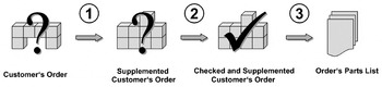
Processing a customer's order.

Rule examples
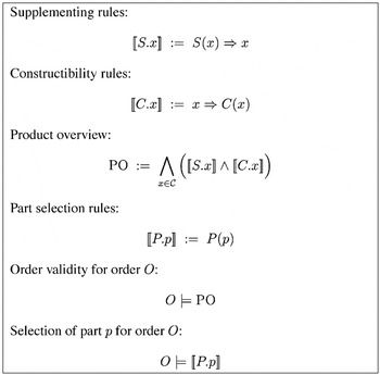
The verification semantics of rules.
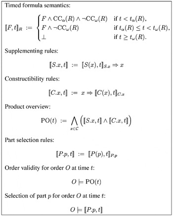
The verification semantics of timed rules.
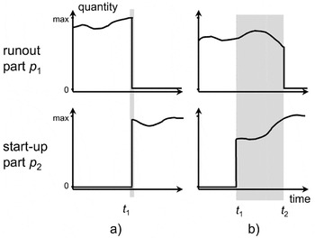
Part exchange: (a) fixed time and (b) overlapping.
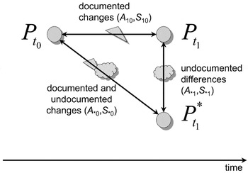
The 3-point approach.
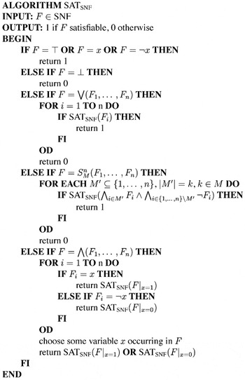
A Davis–Putnam style algorithm for SNF formulae.
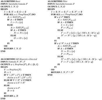
The INO algorithms Basic, Filter, and the variable selection algorithm SAT-Heuristics-Directed.
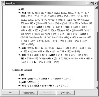
A MUS in BIS.
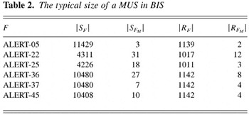
The typical size of a MUS in BIS
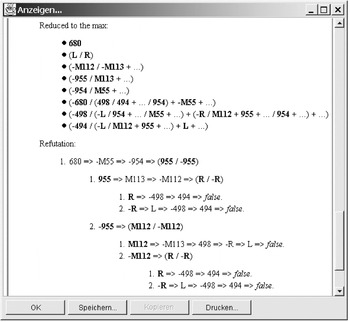
An example of an explanation in BIS.
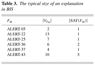
The typical size of an explanation in BIS
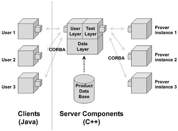
The BIS system architecture.
 You have
Access
- 54
- Cited by