Polymeric materials that are responsive to external stimuli, including temperature, pressure, pH, light, and electric and magnetic fields, are of interest for a wide variety of applications. Given the immense library of available constituents, the composition, functional groups, architecture, and multi-scale morphology of polymeric materials can be tuned to induce dramatic and often reversible changes in shape,[Reference Ohzono, Monobe, Shiokawa, Fujiwara and Shimizu1] volume,[Reference Haraguchi, Li, Song and Murata2] morphology,[Reference Kim, Yoon and Hayward3] and mechanical[Reference Haraguchi and Takehisa4] and optical properties.[Reference Jeong, Jang, Koh, Graham, Jin, Park, Nah, Lee, Cheng and Thomas5, Reference Lee, Lim, Kim and Cho6] By engineering the specific responsiveness, controlled transitions can be used for regulating wetting,[Reference Lee, Lee, Lim, Lee, Lee and Cho7] tunable adhesion,[Reference Lin, Vajpayee, Jagota, Hui and Yang8] expansion/contraction,[Reference Dong, Agarwal, Beebe and Jiang9] specific drug release,[Reference Gupta, Vermani and Garg10] and liquid passage through microfluidic channels.[Reference Ohzono, Monobe, Shiokawa, Fujiwara and Shimizu1] Stimuli responsiveness arises from a system's ability to transition between two states of energy minima when triggered either physically (e.g., mechanically, electrically, magnetically, optically, and thermally), chemically (e.g., cross-linking, cycloaddition, zipping/unzipping, electrochemically, and ionically), or biologically.
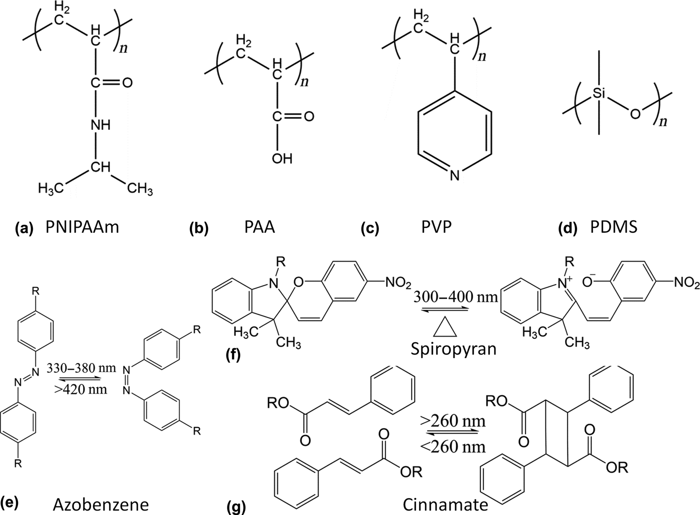
Responsive polymers undergo conformational changes as a result of a change in the polymer chain interactions. Thermo-responsive polymers often possess either a lower or upper critical solution temperature, at which they undergo a coil-to-globule transition or vice versa.[Reference Schmaljohann11] A well-known example is poly(N-isopropylacrylamide) (PNIPAAm), which has a lower critical solution temperature (LCST) of ~32 °C. Above LCST, it becomes hydrophobic and collapses out of water. pH-responsive polymers have functional groups which are able to donate or accept protons under different pH conditions, which results in electrostatic repulsions between the resulting charges along the polymer backbone.[Reference Dai, Ravi and Tam12] Polyacids, such as poly(acrylic acid) (PAA), release protons and swell at pH values above their pKa. Contrarily, polybases such as poly(vinyl pyridine) (PVP) accept protons and swell at pH values below their pKa. Optically responsive polymers are often achieved by the addition of photochromic molecules.[Reference Zhao and Ikeda13] Common light-sensitive molecules include azobenzene, which undergoes a cis–trans isomerization; spiropyran, which ionizes and generates a dissociated ion pair; and cinnamate, which dimerizes and cross-links two molecules in response to UV irradiation.
While polymers readily respond to stimuli in solutions, polymers existing in other states of matter require greater energetic inputs for responsiveness due to their limited segmental motions, dimensional restrictions, and structural integrity. Common states of polymers include cross-linked gels, elastomers, and polymer solids. Stimuli-responsive gels are formed by chemically or physically cross-linking responsive polymers.[Reference Ahn, Kasi, Kim, Sharma and Zhou14] In particular, hydrophilic polymers can be cross-linked to form hydrogels that can swell in solvents, depending on temperature, pH, and ionic strength.[Reference Dong, Agarwal, Beebe and Jiang9–Reference Schmaljohann11] The responsiveness of hydrogels can be tuned by both the constituent polymers and their responsiveness, as well as by the cross-linking density and distribution of the hydrogels. Gels can be glassy in the dry state but exhibit a significant drop in modulus in the swollen state. Elastomers are polymer networks with low cross-linking density, allowing it to have high deformability and swelling in good solvents. Poly(dimethylsiloxane) (PDMS) is a typical elastomer that can be deformed mechanically due to its low elastic modulus, of the order of a few MPa.[Reference Lötters, Olthuis, Veltink and Bergveld15]
Liquid crystal elastomers (LCEs) are another unique class of elastomers, which combine the properties of liquid crystals (orientational order and responsiveness) and polymer networks (rubbery elasticity).[Reference Warner and Terentjev16] Like most elastomers, LCEs can exhibit either an isotropic random coil configuration or an anisotropic stretched chain conformation, and the transition between these two phases can be triggered by a number of stimuli, including heat, light, solvent, and electrical field. Due to the permanent dipoles in the polymer matrices of LCEs and the resulting optical and geometrical anisotropies, LCEs can respond to electromagnetic fields by realigning their mean optical axis parallel to the external field, resulting in orientational changes.[Reference Spillmann, Ratna and Naciri17] In addition, the orientational order of the mesogens can be controlled by temperature or solvent as well as light with the addition of photochromic molecules,[Reference Rousseau and Mather18] resulting in conformation and/or shape change.[Reference Thomsen, Keller, Naciri, Pink, Jeon, Shenoy and Ratna19] Since the strain in the polymer network is created by the anisotropic alignment of mesogens, LCEs exhibit a reversible shape memory effect, i.e., the permanent shape can be recovered upon removal of the stimulus or with the application of an additional stimulus.[Reference Rousseau and Mather18]
Glassy polymers or cross-linked networks typically have limited mobility and low free volume, resulting in restricted stimuli-responsive behaviors. To improve responsiveness, it is common to introduce a copolymer with a lower glass transition temperature (T g) or add fillers to plasticize the polymer matrix and increase the free volume. Polymer networks can also be designed with cross-links, which can be reversibly broken upon triggering.[Reference Kloxin and Bowman20] Polymers which can be programmed with a temporary shape and subsequently recover its permanent shape are known as shape memory polymers (SMPs).[Reference Lendlein and Kelch21, Reference Mather, Luo and Rousseau22] Most commonly, the shape change is thermally induced, whereupon heating the SMP above a transition temperature (T trans), typically the melting temperature (T m) or the T g, will decrease the Young's modulus by two or three orders of magnitude, allowing for the SMP to be deformed to a temporary shape. The temporary shape can then be fixed by fast cooling the sample. Reheating SMP in the temporary shape above T trans triggers the relaxation of the stored elastic energy and the recovery of the permanent shape, which can be again fixed by quenching below T trans. The process can be repeated to program a different temporary shape. Recent work has focused on the design of SMPs with multiple temporary shapes.[Reference Xie23–Reference Xie, Xiao and Cheng25]
To achieve multi-responsiveness, it is common to copolymerize different responsive monomers. It is also possible to embed responsive components within a polymer matrix to impose responsiveness. Typical responsive polymers and their chemical structures are summarized in Fig. 1. More extensive reviews of responsive polymers and their design and applications have been presented in literature.[Reference Liu and Urban26–Reference Roy, Cambre and Sumerlin28] In this review, we will focus on the design of geometrically defined surfaces, specifically micro- and nanopillar arrays from stimuli-responsive polymers or polymers with embedded responsive components for myriad of surface-related applications. Often, the properties of the materials are disproportionately dependent on the surface properties, including the chemistry and topography. While surface chemistry determines the intrinsic properties of the surface, surface topography (i.e., feature size, height, spacing, shape, and lattice symmetry) can be used to significantly alter the properties and add functionality. Inducing changes to the surface structure of polymeric materials results in a large change in its surface properties, including adhesion, wetting, optical appearance, and biocompatibility.[Reference Bae, Kim, Kim, Park, Jeong and Suh29–Reference Hu, Chen, Wang, Zheng and Li32]
Chemical structures of common responsive polymers. (a) Thermo-responsive PNIPAAm, pH-responsive (b) PAA, and (c) PVP, (d) PDMS, and light-responsive (e) azobenzene, (f) spiropyran, and (g) cinnamate.

In nature, there is an abundance of hierarchically patterns which offer multi-scale functionality and tunability, such as the self-cleaning and hydrophobic lotus leaves,[Reference Cheng, Rodak, Wong and Hayden33–Reference Neinhuis and Barthlott35] the chemically sensitive structural color of the “Morpho” butterfly wings,[Reference Kinoshita, Yoshioka and Kawagoe36–Reference Vukusic, Sambles, Lawrence and Wootton38] and the adhesion pad of gecko lizards.[Reference Gao, Wang, Yao, Gorb and Arzt39–Reference Autumn and Peattie41] These properties arise from the micro- and nanostructures of the systems. Advances in micro- and nanofabrication techniques have allowed for the fabrication of multi-scale hierarchical structures with dynamic properties. Physical modification, through the combination of bottom-up self-assembly and top-down lithography techniques, is a simple and well-controlled approach to fabricate artificial multifunctional and well-ordered surfaces.[Reference Bae, Kim, Kim, Park, Jeong and Suh29–Reference Hu, Chen, Wang, Zheng and Li32] Biomimetic high-aspect-ratio (HAR) micro- and nanopillar arrays are topologically well-separated from the underlying substrate. Using responsive polymers to fabricate HAR pillar structures allows for the actuation of the patterned surface without changes to the bulk substrate, and leads to a variety of surface-mediated applications.[Reference Chandra and Yang42] For some applications, it may be desirable to separate the active, responsive component from the bulk substrate. Often, responsive molecules or particles may be added to a polymer system. In this case, the polymer matrix provides the mechanical robustness/flexibility and the platform for actuation. In this Prospective, we present recent studies on responsive pillar arrays, showcasing their tunable behaviors and bio-inspired applications.
Tunable wettability
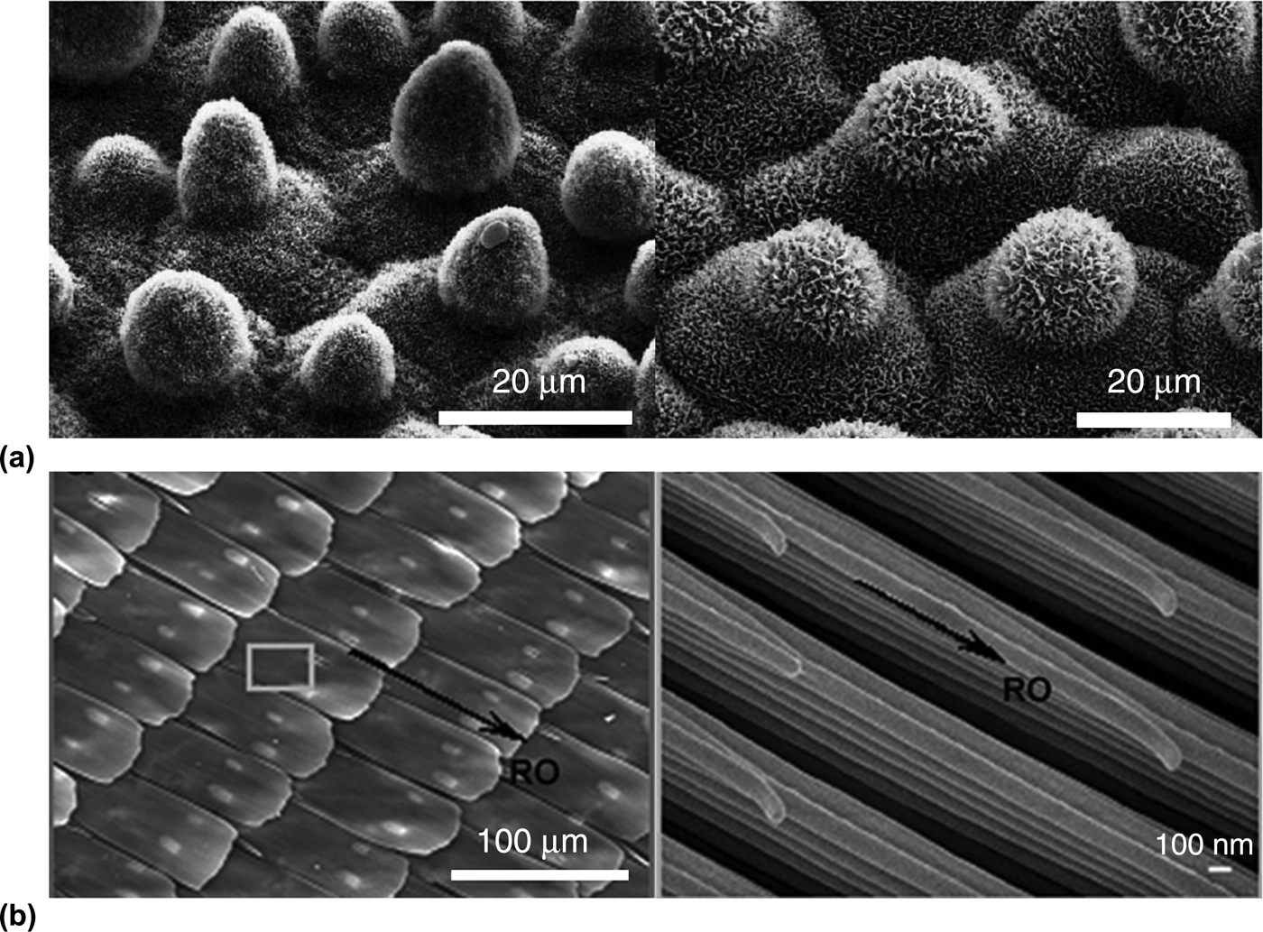
The lotus leaf is the quintessential example of a superhydrophobic surface in nature. The superhydrophobicity and self-cleaning properties of the lotus leaf are attributed to the array of microscale protrusions and the nanoscale roughness on the surface [Fig. 2(a)].[Reference Cheng, Rodak, Wong and Hayden33–Reference Neinhuis and Barthlott35] Decades of studies have shown that the roughness of a surface can dramatically affect its wetting properties, including apparent contact angle and contact angle hysteresis.[Reference Zhang, Shi, Niu, Jiang and Wang43–Reference Feng and Jiang47] A superhydrophobic surface is characterized by a large water contact angle θ w (>150°) with little contact angle hysteresis (typically less than 10°). When a water droplet sits atop a microstructure with air trapped between the droplet and the solid, a composite surface is formed. This surface can be described by the Cassie–Baxter model[Reference Cassie and Baxter48]:
 $$\cos {\theta ^*} = -1+f_s(\cos \theta+1),$$
where θ* is the apparent contact angle of the composite surface, f s is the area of the liquid–solid contact, and θ is the Young's contact angle on a flat surface of the same material.[Reference Cassie and Baxter48] When f s becomes 1, i.e., the droplet is in contact with and wets the whole surface, the surface is described by the Wenzel model[Reference Wenzel49]:
 $$\cos {\theta ^*} = r\cos \theta, $$
where r is the surface roughness, i.e., the ratio of the actual to the apparent surface area.[Reference Cassie and Baxter48]
Hierarchical structures of the (a) lotus leaf[Reference Barthlott and Neinhuis34] (Scale bars: 20 μm) and (b) butterfly wing (Scale bars: 100 μm and 100 nm).[Reference Zheng, Gao and Jiang53]
Another important factor to consider in the design of superhydrophobic surfaces is the contact angle hysteresis, i.e., the difference between the advancing (θ a) and receding contact angles (θ r). The contact angle hysteresis affects the droplet's adhesion to the surface and its ability to roll off with tilting. The sliding angle α, at which a droplet rolls off the surface, can be described by the Furmidge model[Reference Furmidge50]:
 $$\sin \alpha = \displaystyle{{{\sigma _{{\rm lv}}}w} \over {mg}}({\rm cos}{\theta _{\rm r}} - {\rm cos}{\theta _{\rm a}}),$$
where σ lv is the surface tension of the water at the water–air interface, w is the width of the droplet, and m is the mass of the droplet. The “lotus effect” describes a superhydrophobic surface with low contact angle hysteresis and sliding angle, which results in easy roll-off of water particles and self-cleaning due to the low adhesion of water droplets. The “petal effect” describes a superhydrophobic surface with high contact angle hysteresis and high adhesive force.[Reference Feng, Zhang, Xi, Zhu, Wang, Xia and Jiang51]
To mimic the superhydrophobic properties of natural systems, many studies have fabricated artificial substrates with controlled surface roughness. In particular, periodic micro- and nanopillar arrays were fabricated to mimic the surface protrusions of the lotus leaf. Additional functionalities assisted by superhydrophobicity can be found in these natural systems, including the self-cleaning of lotus leaves, paradoxical locomotion of water striders on water, and directional wetting of butterfly wings. Special wettability seen in nature is often correlated to multi-scale structured surfaces. As such, recent research has focused on the fabrication of hierarchically patterned surfaces which not only exhibit extremely large water contact angles, but have low contact angle hysteresis, possess robustness against impact pressure, mechanical rubbing, and extended exposure to outdoor conditions (e.g., sun, heat, and rain), dynamic tuning and directionality, and tunable adhesion.[Reference Liu, Wang and Jiang31] Using responsive materials, the controlled deformation of surface structures can dynamically tune the surface roughness, and therefore the wetting properties.[Reference Xin and Hao52]
The Morpho butterfly wing exhibits directional non-wetting behavior, which arises from its hierarchical structure.[Reference Zheng, Gao and Jiang53] The wings are covered by overlapping micro-sized, periodically arranged rectangular scales, which align radially outward from the central axis of the butterfly body [Fig. 2(b)]. Each scale has nano-sized stripes which are oriented along the same direction as the scale. These stripes consist of multiple layers of cuticle lamellae of different lengths that are stacked stepwise along the microscales. Due to the anisotropy of this structure, water droplets can roll along but are pinned perpendicular to the direction of the nanostripes and microscales. Therefore, many groups have mimicked this structure by fabricating anisotropic micropillar structures, which are bent to induce directional wetting. Oblique electron beam irradiation,[Reference Kim and Suh54] ion beam irradiation,[Reference Rahmawan, Kim, Kim, Lee, Moon and Suh55] and oblique metal deposition[Reference Yoon, Jeong, Kim, Kang, Tahk, Char and Suh56, Reference Chu, Xiao and Wang57] have been used to fabricate tilted polymeric micropillars. By controlling both the surface chemistry and the tilting of the micropillars, the wetting of water droplets can be controlled to be pinned or propagated either uni-directionally or bi-directionally. However, the tilting of these pillars is not reversible.
For reversible and uni-directional wetting, a reconfigurable, water droplet-directing surface has been fabricated from HAR SMP pillars (Fig. 3).[Reference Chen and Yang58] The pillar dimensions are defined in Fig. 3(a). On the originally straight pillar array, water droplets are in the Cassie–Baxter state with a finite sliding angle. When heating the pillar array to a temperature above T g, the pillars can be sheared to form uniformly deformed patterns and cooled below T g to lock the structure [Figs. 3(a)–3(c)]. When the spacing of the pillars is smaller than the pillar height, the pillars can overlap with their neighbors to form saw-tooth-like structures [Fig. 3(c)]. On the deformed pattern, water droplets are in the Wenzel state and become fully pinned to the surface. Because the pillars are sheared in a specific direction, the wetting on tilted pillars is anisotropic, that is, the water contact angles are different in the direction along the tilting and perpendicular to the tilting. The water contact angle is lower along the direction of the deformed pillars [Fig. 3(d)]. This structure is analogous to one-dimensional wrinkled structures, which were previously shown to exhibit directional wetting.[Reference Chung, Youngblood and Stafford59–Reference Khare, Zhou and Yang61] The triple phase line is pinned along the channels because of the higher energy barrier in this direction [Figs. 3(e)–3(g)]. When the deformed pillars form a saw-tooth structure, the height variation adds additional roughness and increases the contact angle parallel to the deformed structure. Unlike previous studies, the deformed pillars can be recovered by reheating to above T g. Exploiting this effect, a surface is designed with wettability contrast to direct water shedding from a region of straight pillars to one of deformed pillars [Fig. 3(h)]. This system allows for localized control of pillar deformation, and therefore localized wetting properties. By further exploiting these properties, an artificial water collection similar to that of the Namib Desert beetle can be envisioned.[Reference Parker and Lawrence62]
Design of water droplet-directing surface made of shape memory pillars. (a) Schematic presentation of the shearing of SMP pillars. (b, c) Scanning electron microscope (SEM) images of the original (b), and deformed (c) pillars. (d) From left to right: droplet viewed perpendicularly to the deformed pillars; water viewed in parallel to the deformed pillars; and the droplet on the original SMP pillars. (e) Triple phase line of water droplet on deformed pillars pinned along the deformed direction (red arrow). (f) Triple phase line of water droplet on deformed pillars unpinned perpendicular to the deformed direction (red arrow). (g) Schematic presentation of a droplet on deformed pillars, showing where the triple phase line is imaged in (e) and (f). (h) Wettability contrast between the original and deformed SMP pillar array. The sample stage is tilted by 10°. The upper half of SMP pillars are in the original state and the lower half is in the fully deformed state, as indicated by the dashed line.[Reference Chen and Yang58]
To locally control the heating of the SMP pillars, we recently reported the incorporation of gold nanorods (AuNRs).[Reference Zheng, Li, Lee and Yang63] Carbon nanotubes or nanofibers have previously been incorporated in the polymer matrix to reduce the thermal resistivity and increase the mechanical strength of SMPs for electroactive shape memory by resistive Joule heating. Incorporation of the AuNRs is not to improve the thermal conductivity. Instead, the AuNRs release heat when excited by a laser, while the conductivity of the SMP itself is low, allowing the local recovery of deformed SMP micropillars [Fig. 4(a)]. Light-responsive SMP micropillars (10 μm diameter, 40 μm height, and 20 μm pitch) were prepared by adding 0.1–0.2 mol% AuNRs. As prepared, the SMP micropillars were transparent and purple in color [Fig. 4(b); blue box]. The SMP pillars were bent at above the T g to various angles depending on the applied force. When bent, the pillars become opaque [Fig. 4(b); red box]. As prepared, the static water contact angle of the SMP micropillars was about 160°. At a bending angle of 40°, the static water contact angle was reduced to 140°. When the pillars were fully collapsed, the contact angle further decreased to 100° [Fig. 4(c)]. The straight pillars, the high water contact angle, and transparency can then be locally recovered by exposure to a green laser (wavelength 532 nm) through a mask for a few seconds [Fig. 4(b); dashed circle].
Design of light-responsive SMP micropillar arrays consisting of AuNRs. (a) Schematic presentation of the setup for local light exposure of SMP pillars. (b) Optical and SEM images of SMP–AuNRs at different stages. From top to bottom: pristine pillars; deformed pillars in the red box; recovered pillars within the dashed blue circle. (c) Water contact angles on various SMP–AuNRs micropillar arrays. From left to right: straight, partially bent (40°), and fully bent pillars.[Reference Zheng, Li, Lee and Yang63]
Another way to dynamically tune the contact area of the substrate with a droplet is by exploiting the anisotropy of nematic LCEs in micropillar arrays.[Reference Wu, Wei, Buguin, Taulemesse, Le Moigne, Bergeret, Wang and Keller64] Because of the anisotropic alignment of the liquid crystal mesogens along the pillar axis, the pillars can reversibly contract (up to 70%) along the long axis and expand radially when heated to above the nematic to isotropic phase transition temperature (T NI). Due to the change of surface topography, the contact angle of glycerol decreases from about 115° at 100 °C to about 80° at 140 °C [Fig. 5(a)] for pillars with diameter of 3 μm and height of 4 μm (D3H4). The area fraction of the surface contacted with the droplet, i.e., the diameter of the pillars, is increased by 12% upon heating to 140 °C. According to the Cassie–Baxter model, the theoretical contact angle is 140°, which is much higher than the measured value, suggesting that the glycerol drop is partially wetting the upper part of the pillar. Above the nematic to isotropic transition temperature, the contact angle of the pillars is similar to that of a flat surface of the same material, suggesting that the drop is in the completely wet Wenzel state. Upon cooling below the transition temperature, the pillars are reverted to their original dimensions but the liquid is trapped in the grooves, thus, the wetting transition cannot be reversed due to the high-energy barrier. With placing a new drop on the surface each time, the authors show that the contact angle can decrease and recover with repeated heating and cooling cycles, respectively [Fig. 5(b)]. The reversible tuning of wetting behaviors is achieved by the combination of the anisotropic LC alignment within the pillars, allowing for the expansion or contraction of the liquid/pillar contact area, and the pillar geometry [Fig. 5(c)].
Design of dynamic wetting using LCE pillars. (a) Variation of contact angle of one glycerol drop on a responsive surface as a function of temperature during a continuous heating process. Flat LCE surface was used as the control. (b) Cyclic measurements of the glycerol contact angle for a structured surface switching between 40 and 140 °C. After each heating process, a new glycerol drop was put on a different place of the same surface at 40 °C. (c) Schemes describing the control of the wetting properties by tuning the roughness of surfaces covered with micropillars. Solid and dotted lines represent the temperature-induced change of wetting properties and the return to the original state using a new drop, respectively. The right images show the contact angles of glycerol on D3H4; D–F correspond to the points shown in panel (b).[Reference Wu, Wei, Buguin, Taulemesse, Le Moigne, Bergeret, Wang and Keller64]
Tunable adhesion
Gecko foot hairs have long been the fascinating natural model for dry adhesives due to their ability to quickly attach to and detach from a surface of almost any roughness or orientation without the use of liquid glue, bridge, or vacuum [Fig. 6(a)]. Each gecko foot pad consists of hundreds to thousands of hairs or setae arranged in lamellae [Fig. 6(b)]. Each seta [diameter ~5 μm, length ~30–130 μm; see Fig. 6(c)] branches out into hundreds to thousands of HAR fibrillar structures (diameter ~0.2–0.5 μm) known as spatulae [Fig. 6(d)]. High adhesion is achieved at a small pulling angle (α) between the millions of pre-sheared gecko spatulae and a surface [Fig. 6(e)] via van der Waals interactions[Reference Autumn, Sitti, Liang, Peattie, Hansen, Sponberg, Kenny, Fearing, Israelachvili and Full40] and possibly together with capillary forces.[Reference Huber, Mantz, Spolenak, Mecke, Jacobs, Gorb and Arzt65] At a high pulling angle, hairs can be detached [Fig. 6(f)]. To mimic this system, many groups have developed HAR pillar arrays to demonstrate dry adhesion, typically with adhesion strength of the order of a few N/cm2.[Reference Rahmawan, Kim, Kim, Lee, Moon and Suh55, Reference Yoon, Jeong, Kim, Kang, Tahk, Char and Suh56, Reference Jeong, Kwak and Suh66–Reference Reddy, Arzt and del Campo68] To successfully mimic the gecko system, it is not only essential to achieve dry adhesion but also easy detachment. Therefore, the artificial pillar systems must also be responsive and reversible.
Structures of the gecko's foot hair and the experimental setup for measuring the adhesive force. (a) Tokay gecko (Gekko gecko) with toe outlined. (b–d) SEM images of (b) rows of setae from a toe, (c) a single seta, and (d) the finest terminal branches of a seta, called spatulae. (e) Single seta attached to a micro-electromechanical system (MEMS) cantilever capable of measuring force production during attachment parallel and perpendicular to the surface. (f) Single seta attached to an aluminum bonding wire capable of measuring force production during detachment perpendicular to the surface. α is the angle between setal stalk and wire gauge.[Reference Autumn, Liang, Hsieh, Zesch, Chan, Kenny, Fearing and Full108]
For example, a stretchable dry adhesive is fabricated with micropillars (20 μm in diameter, height, and spacing) atop microwrinkles with wavelength λ = 80 μm [Figs. 7(a) and 7(b)].[Reference Jeong, Kwak and Suh66] Here, the micropillars mimic the microstructure of the gecko foot, while the mechanical tilting of the pillars induces adhesion changes. By mechanically stretching the wrinkles made of elastomeric PDMS, the angle of the micropillar contact with a surface can be altered reversibly. Thus, the normal and shear adhesion of the substrate could be dynamically controlled. When the substrate is fully stretched and the wrinkles flattened, the micropillars are in the vertical position with maximal achievable contact. This results in a relatively high normal (~10.8 N/cm2) and shear (~14.7 N/cm2) adhesion. When the substrate is released, the micropillars are tilted and the contact area and resulting adhesion is drastically reduced. The substrate is shown to be durable for up to 100 cycles of attachment and detachment. This directionality dependence and reversibility is comparable with that of the gecko foot [Figs. 7(c) and 7(d)].
Design of reversible dry adhesive based on wrinkling of PDMS micropillars. Schematic presentation of the contact of the pillars with a flat substrate in the (a) released and strained states. SEM images of the (b) wrinkled and (c) as-prepared micropillars. Measurement of macroscopic normal (d) and shear (e) adhesion forces with a PDMS adhesive patch (thickness, 1 mm; size, 1 × 1 cm2) having micropillars at different strain levels (δR/δS) against the smooth glass surface under a preload of 0.1 N/cm2.[Reference Jeong, Kwak and Suh66]
Alternatively, the shape memory effect of glassy polymers has been exploited to fabricate reversible, dry adhesives. By controlling the T g, the applied pre-load, and the surface chemistry, strong reversible dry adhesion is demonstrated in epoxy-based SMP bulk films.[Reference Xie and Xiao69, Reference Wang and Xie70] The release of the adhesive is achieved by macroscopically curving the samples at above the T g[Reference Xie and Xiao69] or by breaking the non-covalent hydrogen bonds between the two epoxy surfaces grafted with branched polyethyleneimine.[Reference Wang and Xie70] The latter is achieved through a peeling mechanism above T g. The contact area of an SMP adhesive can be microscopically tuned by creating SMP micropillar arrays with controlled deformation [Fig. 8(a)],[Reference Reddy, Arzt and del Campo68] Micropillars are used here due to their high mechanical compliance and deformability. As fabricated, SMP micropillar arrays [Fig. 8(b)] have relatively high adhesion with a pull-off force of about 30 kPa. The SMP is a cycloaliphatic polyetherurethane block copolymer phase-separated into two glassy domains with hard (T g 120–140 °C) and soft segments (T g 51 °C). The soft segments act as the shape memory switch, while the hard segments act as physical cross-linker to lock the deformed temporary shape. Upon heating to above the T g of the soft segments (referred as T trans in Fig. 8), the soft segments become flexible (storage modulus, E′ changes from 1 GPa at 25 °C to 70 MPa at 70 °C). By applying a shear force, the SMP pillars can be tilted uni-directionally [Fig. 8(c)], switching the surface to a temporary non-adhering state with a negligible pull-off force. Upon reheating to above T trans, the physical cross-links are unlocked, and the straight pillars [Fig. 8(d)] and adhesive state are recovered with a decreased pull-off force, ~12 kPa [Fig. 8(e)].
(a) The micropatterned surface is deformed by heating of the original Tecoflex surface with vertical pillars, followed by pulling of a glass slide over the top of the surface while the sample is at T = 70 °C. Cooling the system in the deformed position stabilizes the non-adhesive, tilted pattern. Recovery occurs by heating the pattern above its T trans. SEM images of Tecoflex pillars with r = 10 μm, h = 100 and 20 μm interpillar spacing. (b) Original pattern. (c) Tilted pillars after deformation at 70 °C and fixation in the deformed state by cooling below T trans. (d) Recovered pillars after reheating at 70 °C. (e) Load–displacement curves measured on the micropatterned surfaces.[Reference Reddy, Arzt and del Campo68]
Velcro tape, based on the interlocking mechanism of hooks and loops of Burdock seeds,[Reference De71, 72] is a quintessential example of a widely used reversible biomimetic dry adhesive [Figs. 9(a) and 9(b)]. Compared with gecko adhesion, which is of the order of a few N/cm2, Velcro has achieved adhesion strength of ~120 N/cm2.[Reference Freeman and Golden73] Unlike the detachment of the gecko foot when pulled at an angle to the surface, more hooks and loops are engaged when Velcro is pulled parallel to its plane, resulting in higher adhesion strength. However, miniaturization of this mechanism has been difficult due to limitations in fabrication techniques to create hooks and loops in the micron scale. Instead, many recent studies have focused on enhanced dry adhesion between two surfaces with complementary structures, which exhibit anisotropic adhesion, i.e., large shear adhesion compared with normal adhesion.[Reference Chen, Chiang, Lai, Xie and Yang74–Reference Pang, Lee, Kim, Kim, Kim, Ahn and Suh83] In nature, interlocking surfaces can be found in the wings of beetles and the valves of diatoms with complementary structures [e.g., cones or triangles, see Figs. 9(c) and 9(d)].[Reference Pang, Kim, Bae, Kang, Kim and Suh82, Reference De Stefano, De Stefano and Congestri84] Through the use of patterned structures, including random core–shell nanowires[Reference Ko, Lee, Schubert, Chueh, Leu, Fearing and Javey76] and HAR polymer pillar arrays,[Reference Pang, Kim, Bae, Kang, Kim and Suh82] enhanced shear adhesion has been demonstrated due to the increased contact between complementary features. Pang et al. have recently demonstrated the use of anisotropic interlocking adhesion for pressure sensors.[Reference Pang, Kang, Kim and Suh81–Reference Pang, Lee, Kim, Kim, Kim, Ahn and Suh83] Nevertheless, it is difficult to avoid buckling and collapsing of the pillars in any real applications, which is often considered detrimental to pillar–pillar contact at the interface, thus, lowering the adhesion strength.
(a) Schematic illustration of Velcro.[Reference De71] (b) Photograph of a Burdock seed.[72] (c, d) SEM images of the (c) microstructure of microhairs on the surface of a beetle wing used for wing-locking[Reference Pang, Kim, Bae, Kang, Kim and Suh82] and (d) interlocking structure of valve structure of diatoms.[Reference De Stefano, De Stefano and Congestri84] Scale bars, 5 μm.
By exploiting the shape memory effect and harnessing the buckling of HAR pillars, we show that both the normal and shear adhesion can be enhanced using complementary buckled SMP arrays made of diglycidyl ether of bisphenol A epoxy[Reference Chen, Chiang, Lai, Xie and Yang74] through a combination of indentation and interweaving mechanisms (Fig. 10). When two SMP pillar arrays are contacted at 80 °C (20 °C above T g) with a preload larger than the critical buckling threshold, the pillars buckle and become indented and/or interweaved with each other [Fig. 10(a)]. The buckling behavior was confirmed by finite-element analysis [Fig. 10(b)]. The engaged structure is locked when the sample is cooled to room temperature, resulting in strong adhesion forces, ~53.6 ± 2.1 N/cm2 in the normal direction and ~71.9 ± 23.2 N/cm2 in the shear direction. These forces are much larger than those measured for non-interlocking SMP surfaces: pillar-to-flat (12.3 ± 8.8 N/cm2, normal and 15.0 ± 2.3 N/cm2, shear) and flat-to-flat contact surfaces (7.1 ± 5.0 N/cm2, normal and 15.8 ± 2.0 N/cm2, shear) [Fig. 10(c)]. The pillars can easily detach from each other when reheated to 80 °C. Using HAR micropillars, the contact area between the two complementary surfaces is significantly increased. In addition, the HAR of the pillars ensures that the critical aspect ratio for buckling is exceeded, allowing the SMP pillars to buckle against each other to maximize the contact area. While the normal and shear adhesion strengths are similar, the difference between them increases when the spacing ratio is increased. The overall adhesion also decreases with increasing spacing. Despite the significant increase of adhesion strength compared with the literature values (typically 10–20 N/cm2 or less), buckling-based interlocking adhesives is for one-time use only. The indentation and/or interweaving of buckled pillars permanently deform the pillars, which cannot be completely recovered to the original straight configuration after reheating.
Design of interlocking adhesive system using SMP micropillars (diameter, 1 μm, aspect ratio, AR = height/diameter 4). (a) Schematic presentation of engaging pillar-to-pillar contact and adhesion measurement. (b) Finite element simulation of the contact process and collapse between two sets of pillars. (c) Measured adhesion strength from pillar-to-pillar, pillar-to-flat, and flat-to-flat contacts in the normal and shear directions. The spacing ratio = pillar-to-pillar distance/diameter, α = 2.[Reference Chen, Chiang, Lai, Xie and Yang74]
To enhance adhesion strength while not permanently deforming the pillars in contact, we embedded nanoparticles into the tips of elastomeric micropillars (Fig. 11).[Reference Rahmawan, Kang, Lee, Suh and Yang77] The interactions between nanoparticles from the complementary pillars will provide the necessary interlocking mechanism, while the elastomeric nature of the pillars will allow for recovery of the deformed pillars, therefore reuse of the adhesive. Silica nanoparticles (diameter = 100 nm to 1 μm) were drop-cast over a PDMS mold (square array of cylindrical pillars with diameter = 5 μm) and bladed by a glass slide in one direction. UV-curable polyurethane acrylate precursor was then back-filled into the mold and photo-polymerized [Figs. 11(a) and 11(b)]. Two complementary surfaces can then be contacted and tested for shear adhesion strength [Fig. 11(c)]. The silica nanoparticles act as protrusions on the tip of the micropillars, which can be approximated as spatula-tipped pillars [Fig. 11(d)]. The composite pillar arrays have shear adhesion strength 48.5 N/cm2, an order of magnitude higher than pristine pillar arrays (4.1 N/cm2). The adhesion strength is found to be proportional to the particle size and the aspect ratio of the micropillars, and inversely proportional to the spacing ratio between the micropillars [Fig. 11(e)]. Similar to other systems with interlocking adhesion, particle-embedded pillars exhibit anisotropic adhesion strength, with their normal adhesion much lower than shear adhesion. However, since the pillars are elastomeric, two complementary surfaces can be detached in the normal direction without stripping the pillars from the supporting substrate. Therefore, the adhesive is reusable.
Design of interlocking adhesive system using micropillar arrays embedded with nanoparticles. (a–c) Schematic presentations of (a) the fabrication process, (b) the shearing of the interlocking pillars, and (c) a single pillar individual particle-embedded micropillar, approximated by spatula-tipped micropillar. (d) Top to bottom: SEM image of a particle-embedded micropillar; fluorescence image showing the distribution of silica nanoparticles at the tip of the micropillars. (e) Measured shear adhesion strength of smooth versus particles-embedded dual-scale micropillars (diameter, 5 μm) as a function of the spacing ratio. AR = 8.[Reference Rahmawan, Kang, Lee, Suh and Yang77]
Tunable optical properties
Besides superhydrophobicity and directional wetting, butterfly wings are well known for their structural colors. Structural color results from the interference, diffraction, and scattering of light from micro- or nanostructures with lengths scales of the order of the wavelength of light. They are typically brighter and shinier than pigment colors, which could fade away over time under the sun. Structural color can be divided into two classes: angle-dependent color from coherent Bragg refraction on periodic structures, as seen in some of the butterfly wings and beetle scales,[Reference Kinoshita and Yoshioka85–Reference Srinivasarao87] and angle-independent color from quasi-amorphous structures, as seen in Morpho butterfly wings, bird feathers and mandrill skin.[Reference Takeoka88] While brilliant color is aesthetically pleasing, switchable color and/or transparency to suit the local environment may be desired in organisms for camouflage, signaling, or mating purposes.[Reference Stavenga, Leertouwer, Marshall and Osorio89–Reference Liu, Dong, Liu, Zheng and Zi91] For example, color changes are observed for Morpho butterfly wings in different vapors[Reference Potyrailo, Ghiradella, Vertiatchikh, Dovidenko, Cournoyer and Olson37] [Fig. 12(a)] and longhorn beetle scales at different levels of humidity[Reference Liu, Dong, Liu, Zheng and Zi91] due to changes of refractive index in the surrounding medium. Meanwhile, squids and octopi can switch between transparency and red color to become invisible to a predatory fish in down-welling light or to a predatory fish with bioluminescent searchlights, respectively, by stretching/contracting their skin to reveal/hide the pigments embedded within their chromatophores [Fig. 12(b)].[Reference Zylinski and Johnsen92, Reference Izumi, Sweeney, DeMartini, Weaver, Powers, Tao, Silvas, Kramer, Crookes-Goodson, Mathger, Naik, Hanlon and Morse93] Previously, many groups have demonstrated the tuning of photonic crystals, which are characterized by periodically modulated refractive index, to switch between diffraction coloring and opaqueness in response to various stimuli.[Reference Park and Lee94–Reference Arsenault, Clark, von Freymann, Cademartiri, Sapienza, Bertolotti, Vekris, Wong, Kitaev and Manners97] However, such structures are unable to achieve transparency.
Dynamic coloring and transparency of biological systems. (a) Selective vapor response based on hierarchical photonic structures and demonstrated using Morpho sulkowskyi iridescent scales. Measurements of differential reflectance spectra ΔR provide information about the nature and concentration of the vapors: ΔR = 100% times (R/R 0 − 1), where R is a spectrum collected from scales upon vapor exposure and R 0 is a spectrum collected from scales upon exposure to a carrier gas (dry N 2).[Reference Potyrailo, Ghiradella, Vertiatchikh, Dovidenko, Cournoyer and Olson37] (b) Left to right: Images of Onychoteuthis banksii showing the chromatophores contracted and the animal transparent under ambient light conditions; with the chromatophores expanded and the animal pigmented when subjected to directed light; optical responses of O. banksii to three bouts of directed light. The blue line indicates response to blue light, and the red line indicates response to red light. Yellow boxes with symbols show the onset and offset of each lighting bout. O. banksii stretches to expose chromatophores in response to blue light.[Reference Zylinski and Johnsen92]
Chandra et al. have exploited capillary force induced clustering of polymeric micropillar arrays (diameter, 0.75–1 μm, aspect ratio up to 12, pitch, 1.5–2 μm) and demonstrated switching from a colored film to ultrathin whiteness to transparency.[Reference Chandra, Yang, Soshinsky and Gambogi98] The unique optical properties are realized by a capillary-force-induced instability when drying poly(2-hydoxylmethacrylate-co-methyl methacrylate) (PHEMA-co-PMMA) micropillar arrays of different elastic modulus. The structural color arises from the Bragg diffraction from the straight, highly ordered pillars; the whiteness comes from the laterally collapsed, randomly arranged pillars; and the transparency from the ground collapsed pillars. However, the color of the original pattern is irrecoverable due to large van der Waals force between collapsed pillars. Lee et al.[Reference Lee, Lee, Lim, Lee, Lee and Cho7] have reported the reversible stretching of tapered PDMS nanopillar arrays (top diameter = 150 nm; bottom diameter = 300 nm; height = 150, 350, 700 nm) on a microwrinkled PDMS film (wavelength λ = 31 μm, amplitude A = 4.4 μm) for mechanically tunable wetting and transparency (Fig. 13). PDMS substrates pre-patterned with nanopillars were pre-stretched and treated with oxygen plasma to induce wrinkling [Fig. 13(a)]. As fabricated, the substrates are opaque but become transparent with strain [Figs. 13(b) and 13(c)]. The nanopillars render the substrates superhydrophobic. The switchable transmission (transparent ↔ opaque) is achieved primarily by reversibly flattening the microwrinkles, while the nanopillars are rather transparent in the visible wavelength.
(a) Schematic illustration of the fabrication process of nanopillars (diameter, 150 nm) on microwrinkles (wavelength λ = 31 μm and amplitude A = 4.4 μm). (b) Transmittance spectra of the multi-scale structured PDMS films (with nanopillars of different aspect ratios) as a function of the mechanical state at normal incident light. (c) Optical images of the MNA film overlaying a printed paper.[Reference Lee, Lee, Lim, Lee, Lee and Cho7]
We recently reported the reversible wrinkling of PDMS micropillars and demonstrated tuning between three states, from opaqueness to structural color display to transparency (Fig. 14).[Reference Lee, Zhang, Cho, Cui, Van der Spiegel, Engheta and Yang99] Here, the surface-wrinkling effect is used to reversibly tilt PDMS micropillars. Due to the matching of the pillar (diameter = 1 μm, height = 4 μm, and spacing = 1 μm) and wrinkle dimensions (wavelength λ = 2.4 μm, and amplitude A = 750 nm), the wrinkle formation is confined by the micropillar array, which is different from the system by Lee et al.[Reference Lee, Lee, Lim, Lee, Lee and Cho7] Therefore, the pattern and wrinkle morphology, orientation and dimensions are controlled by varying the treatment duration of the oxygen plasma and the angle of uniaxial stretching with respect to the pillar array axis. While the original PDMS film exhibited angle-dependent colorful reflection due to Bragg diffraction of light from the periodic pillar array, the tilted pillar film appeared opaque. Upon re-stretching the film to the original pre-strain, the grating color is restored due to the straightened pillars and ~30% transmittance is recovered. Further stretching led to higher transmittance due to the increasing spacing between the pillars [Figs. 14(b)–14(f)]. The switch in optical properties is completely reversible over many cycles and is applicable for a cheap, controllable optical window. The reversible switch between color, transparency, and opacity is achieved by the micropillar array structure and the ability to reversibly actuate the orientation and spacing of the pillars.
Tilted micropillars on wrinkled elastomers as a reversibly tunable optical window. Pillar diameter D = 1 μm, height H = 4 μm, and pitch P = 2 μm. The wrinkles have wavelength λ = 2.4 μm, and amplitude A = 750 nm. (a) From left to right: schematic illustrations of the tilted micropillar array after releasing the pre-strain, flattened micropillar array after re-stretching to 30%, and expanded pillar array after further stretching to 40%. Photographs of the substrate with incident light normal to the sample at (b) 0%, (c) 30%, and (d) 40% strain, and the corresponding SEM images for strains (e) 0% and (f) 30%. (e–f), Scale bars, 4 μm.[Reference Lee, Zhang, Cho, Cui, Van der Spiegel, Engheta and Yang99]
Actuators
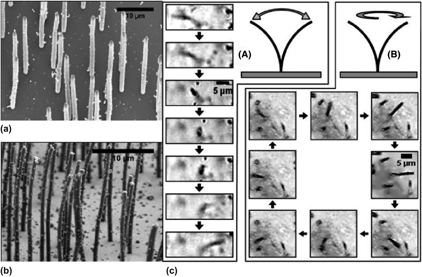
Mechanical actuation of HAR pillar structures is essential in natural systems for functions such as motion, self-cleaning, and food capture. For example, microorganisms use flagella for propulsion[Reference Brennen and Winet100, Reference Urutseg and Kohidai101] and some respiratory tracts use cilia (diameter ~200 nm and length ~10 μm) for active anti-fouling (Fig. 15).[Reference Daghlian102–Reference Sleigh, Blake and Liron104] To mimic the motion of the cilia, HAR micro- and nanopillar arrays (diameter 100 nm–1 μm, AR up to 125) are fabricated from PDMS embedded with 18 wt% maghemite iron oxide (Fe2O3) nanoparticles [Fig. 16(a)].[Reference Evans, Shields, Carroll, Washburn, Falvo and Superfine105] In this case, the HAR and low modulus of the PDMS pillars lends its mechanical flexibility, while the nanoparticles are magnetic responsive. When actuated with an externally applied magnetic field, the pillars exhibit both linear and rotational responses, similar to that of biological cilia [Fig. 16(b)].
(a) Schematic presentation of flagellum and cilium motion.[Reference Urutseg and Kohidai101] (b) SEM micrograph of the cilia lining the respiratory epithelium in the lung (Scale bar: 5 μm).[Reference Daghlian102]
(a, b) SEM images of magnetically actuated PDMS pillar arrays embedded with Fe2O3 nanoparticles after being dried using supercritical CO2. Pillar diameters, (a) 1 μm and (b) 700 nm. (c) Actuation of a single nanorod. (A) Linear and (B) rotational actuation strokes of a single 500 nm pillar with an aspect ratio of 50.[Reference Evans, Shields, Carroll, Washburn, Falvo and Superfine105]
The responsive layer can also be separated from the pillar structures. HAR silicon nanopillars (diameters 100–300 nm, heights 5–8 mm, aspect ratios 15–80, and periodicities 2–4 μm) are embedded within a polyacrylamide gel (PAAG) grafted to a substrate [Figs. 17(a)–17(c)].[Reference Sidorenko, Krupenkin, Taylor, Fratzl and Aizenberg106] In this case, the hydrogel is the active, responsive layer while the stiff Si nanopillars provide the surface topography. The nanopillars can be tilted by the swelling or contraction of the hydrogel layer in response to humidity changes. Depending on the type of confinement of the Si nanopillars to the substrate, either non-touch [Fig. 17(d)] or directly attached [Fig. 17(e)], the nanopillars can be highly tilted or bent upon drying. Based on a similar concept, epoxy microfins (2 μm wide, 10 μm long, and 18 μm high) attached to a substrate are partially embedded in a pH-responsive hydrogel, poly(acrylamide-co-acrylic acid) or temperature-responsive PNIPAAm hydrogel layer, while the tips are stamped with catalysts or fluorescent dyes. The microfins can bend into and out of the reactant-containing layer actuated by the hydrogel layer, leading to repeated cycles of exothermic catalytic reactions synchronized with the mechanical motion of the microfins [Fig. 17(f)].[Reference He, Aizenberg, Kuksenok, Zarzar, Shastri, Balazs and Aizenberg107] In this system, it is essential to have HAR pillars well separated from the reactant-containing liquid layer when inactive, as well as the underlying actuating hydrogel layer for maximal bending.
(a) Schematic presentation of the structure and composition of the PAAG film grafted to the Si/SiO2 substrate via the polyglycidyl methacrylate (PGMA) anchoring layer. (b) SEM of a sample high AIRS composed of an array of silicon nanocolumns. (c) Hydrogel synthesis in the confinement of the AIRS and a secondary substrate. (d) Hybrid hydrogel-AIRS (HAIRS)-1 design. The nanocolumns, embedded into the hydrogel layer grafted to the PGMA-modified confining surface, break from the original wafer upon the separation of the confining substrates and become fully transferred onto the secondary surface. (e) Hybrid HAIRS-2 design. The hydrogel film is attached directly to the AIRS silicon wafer. Nanocolumns remain attached to the surface and bend upon drying.[Reference Sidorenko, Krupenkin, Taylor, Fratzl and Aizenberg106] (f) Schematic presentation of chemical reactions triggered by HAIRS bending. Left, fluorescent quenching. Right, platinum-catalyzed decomposition of hydrogen peroxide.[Reference He, Aizenberg, Kuksenok, Zarzar, Shastri, Balazs and Aizenberg107]
Conclusion
In this Prospective, we present recent literature on the bio-inspired design of responsive polymer pillar arrays with applications in tunable wetting, adhesion, optical properties and actuation. Biological systems achieve changes to their properties and functionalities by modulating their structures on multiple length scales. Inspired by nature, artificial HAR polymer pillar structures have been fabricated to engineer controlled and dynamic modifications to the surface topography, which can be triggered by a number of stimuli. Although many applications have been demonstrated at the laboratory scale, there are still limitations in applying polymer pillar systems at a commercial scale. Primarily, HAR pillars are prone to collapse due to mechanical instability. We envision the review presented here on existing strategies of fabrication and manipulation of HAR polymer pillars will shed light on applying HAR pillars to new paradigms, such as soft robotics and tissue engineering. Furthermore, by coupling with new innovations in patterning methods, such as three-dimensional printing, and combining bottom-up assembly and top-down lithography techniques, we expect researchers to create hierarchical structures with better programmability, controllability, and reusability on a large-scale to realize the maximum potential of responsive polymer pillar systems.
Acknowledgments
The work shown here by the Yang laboratory was supported by the National Science Foundation (NSF) CAREER grant (no. DMR-0548070), GOALI grant (no. DMR-1105208), and EFRI-SEED grant (no. EFRI-1038215), and ACS/PRF grant (no. 50911-ND7).