I. INTRODUCTION
In the AlF3–CsF system, only one phase has been characterized by a single-crystal structure determination, that of hexagonal (P
 $$\bar 62m$$
, Z = 3) α-CsAlF4 (Lösch and Hebecker, Reference Lösch and Hebecker1979), isostructural to CsCrF4 (Babel and Knoke, Reference Babel and Knoke1978). The structure is built up from condensed infinite triple chains of corner-sharing AlF6 octahedra leading to the (Al3F12)
n
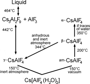
3n− formula. Two other CsAlF4 phases (named β and γ) were characterized later (Bentrup et al., Reference Bentrup, Le Bail, Duroy and Fourquet1992) by a structure determination by powder diffractometry (SDPD), being products of the dehydration of Cs[AlF4(H2O)2] under different conditions. The γ-CsAlF4 phase (orthorhombic, Pnma, Z = 12), built up from condensed chains of corner-sharing AlF6 octahedra, is formed at 150°C from the above hydrate at atmospheric pressure and under inert atmosphere. The β-CsAlF4 phase (tetragonal, I
 $\bar 4$
c2, Z = 20), isostructural with β-RbAlF4 (Fourquet et al., Reference Fourquet, Plet and De Pape1980), built up from the disconnected tetragonal-tunsten-bronze-like layers, is formed at 200°C at atmospheric pressure and under inert atmosphere from an amorphous CsAlF4 form obtained also from the hydrate, but at 150°C under vacuum. The following irreversible transitions were established at atmospheric pressure: β → γ at 344°C under anhydrous and inert atmosphere, whereas β → α at 350°C with traces of water. It was thus believed that the γ-form was the stable one, obtained in strictly anhydrous conditions of synthesis, the β-form being metastable and the α-form favoured by a synthesis in presence of water traces. A reversible reaction γ-CsAlF4 ↔ Cs3Al2F9 + AlF3 was observed at 442°C, and this Cs3Al2F9 was claimed to be isostructural with Cs3Fe2F9 (Dance et al., Reference Dance, Mur, Darriet, Hagenmuller, Massa, Kummer and Babel1986), so that it should contain the face-sharing fluoroaluminate anion Al2F9
3−. However, neither ab initio structure solution nor a structure refinement was presented.
During a more recent study of the phase diagram of the AlF3–CsF system (Chen et al., Reference Chen, Cao and Zhang1997), the existence of β-, γ-CsAlF4, and Cs3Al2F9 were not confirmed. If β-CsAlF4 may not appear in that diagram, as explained above, the two others should (Figure 1). In that study, the method of synthesis is questionable since the samples were not prepared in the solid state by direct mixing of the adequate proportions of AlF3 and CsF, but “25 samples (were prepared) by reacting mixtures of anhydrous AlF 3 with solutions of CsF in HF”. These samples were furthered heated until dry at 200°C, and then annealed for 48 h at higher temperatures (between 400 and 600°C depending on the composition). The problem here is that reactions may take place in solution at the beginning (i.e. formation of definite compounds in the solution, even at ambient or warm temperatures), so that the final compositions will be eventually different from the initial ones. A strong argument in this sense is the fact that the proposed “CsF–2AlF3” compound (CsAl2F7) is found to have a hexagonal cell (a = 9.455 Å, c = 3.703 Å) identical to that of α-CsAlF4. Indexation of the powder patterns was proposed, but structure solutions were not presented for any of the claimed four compounds Cs3AlF6, CsAlF4 (α- and β-forms), Cs2AlF7, and CsAl3F10. The form α-CsAlF4 was proposed to have a reversible transition to a β-form at 422°C, this later form (indexed in orthorhombic symmetry from only 12 reflexion positions) being obviously different from the β-CsAlF4 listed in the paper of Bentrup et al. (Reference Bentrup, Le Bail, Duroy and Fourquet1992); so let us call it β′.
Origin of Cs3Al2F9, β-, and γ-CsAlF4. If β-CsAlF4 may not appear in the solid-state AlF3–CsF system, the two others should.

Existence of Cs2AlF5, another compound of the Cs–Al–F family with yet unknown crystal structure, was for the first time mentioned by Bentrup (Reference Bentrup1991), who claimed to have prepared it by dehydration of Cs2[AlF5(H2O)] at 171°C. Symmetry of the cell was proposed to be orthorhombic, space group not determined, and it was concluded that “merely the chain type of Cs 2 AlF 5 has not been determined up to now.” If assuming isostructurality with orthorhombic Rb2FeF5 (Dance et al., Reference Dance, Soubeyroux, Sabatier, Fournes, Tressaud and Hagenmuller1980), the structure would be built of corner-sharing (AlF6)3− octahedra.
This study provides a resolution of aluminium coordination ambiguity in the structures of Cs3Al2F9 and Cs2AlF5. As these compounds do not form single crystal of reasonable size for X-ray diffraction, their structures were solved from laboratory powder diffraction data, refined by Rietveld (Reference Rietveld1969) method and finished by energy minimization in the solid state (see, e.g., Le Bail and Smrčok, Reference Le Bail and Smrčok2011; Oszajca et al., Reference Oszajca, Smrčok and Lasocha2013; Smrčok et al., Reference Smrčok, Mach and Le Bail2013).
II. EXPERIMENTAL
A. Synthesis of Cs2AlF5
A sample of Cs2AlF5 was prepared according to the Bentrup (Reference Bentrup1991) process. It was maintained at 280°C for several days in order to improve its originally poor crystallinity and then used for data collection. Cs2AlF5 decomposes into a mixture of CsAl3F10 as defined by Chen et al. (Reference Chen, Cao and Zhang1997) and an unknown at 300°C, for which a rhombohedral cell was proposed (see the supplementary material).
B. Synthesis of Cs3Al2F9
According to the reversible reaction γ-CsAlF4 ↔ Cs3Al2F9 + AlF3 (at 442°C) (Bentrup et al., Reference Bentrup, Le Bail, Duroy and Fourquet1992), a sample was quenched at 460°C (a platinum tube quickly dropped in cold water). The presence of AlF3 is hence unavoidable and it was also not possible to completely exclude the presence of γ-CsAlF4 back reaction product.
III. RESULTS
A. Crystal structure determination and Rietveld refinement of Cs2AlF5 and Cs3Al2F9
Indexing of the powder pattern of Cs2AlF5 was realized using the McMaille software (Le Bail, Reference Le Bail2004) leading to a primitive orthorhombic cell. The figures of merit (FoMs) were M
20 = 35.7 (de Wolff, Reference de Wolff1968), F
20 = 54.6 (0.0099, 37) (Smith and Snyder, Reference Smith and Snyder1979), and McM
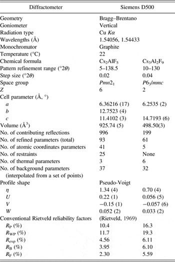
20 = 132.5 (Le Bail, Reference Le Bail, Clearfield, Reibenspies and Bhuvanesh2008). The space-group determination was ambiguous, obscured by peak overlapping for three reasons: (i) the fortuitous fact that b ~ 2a; (ii) the pseudo-hexagonal cell consequence of c ~ a
 $\sqrt 3 $
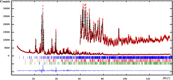
(Table I); and (iii) the broadened peak shapes because of the still poor crystallinity, in spite of the long heating at 280°C. The structure solution was carried out in direct space using the ESPOIR software (Le Bail, Reference Le Bail2001), moving in the cell the appropriate number of Cs, Al, and F atoms by a Monte Carlo process. Calculations were performed in a quite long series (>20) of centric or acentric space groups selected because they were all leading to similarly satisfying Le Bail fits (Le Bail, Reference Le Bail2005). A partial starting model was finally recognized (octahedra making sense) in the Pmn21 space group and the structure could be completed by alternating Rietveld refinements using the FULLPROF software (Rodriguez-Carvajal, Reference Rodriguez-Carvajal1993) and Fourier difference synthesis calculated using SHELX (Sheldrick, Reference Sheldrick2008). The main impurity (traces of the higher temperature rhombohedral phase cited above) was treated by the Le Bail method. A series of weak peaks appeared to correspond well to the Cs3Al2F9 powder pattern, so that this contribution was modelled with the fixed atomic coordinates (Figure 2). No missing symmetry was found using the PLATON software (Spek, Reference Spek2009) and acentricity of the structure was confirmed.
(Color online) Refined diffraction pattern from the laboratory data (CuKα) for Cs2AlF5 at 22°C. Red dots represent the observed data, and the black line represents the calculated ones. Bragg ticks are the peak positions (three sets from up to down: 97% Cs2AlF5, rhombohedral high-temperature form – Le Bail fit, thus not taken into account for the percentages estimations – and Cs3Al2F9 < 3%) and the blue curve shows the difference between the observed and calculated patterns.

Experimental and Rietveld refinement details for Cs2AlF5 and Cs3Al2F9.

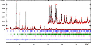
For Cs3Al2F9, the Rietveld refinement was readily managed by starting from the Cs3Fe2F9 atomic coordinates (Dance et al., Reference Dance, Mur, Darriet, Hagenmuller, Massa, Kummer and Babel1986) and by adding the AlF3 and γ-CaAlF4 impurities with their atomic coordinates fixed. The contribution of a very small quantity of the cubic Cs3AlF6 (Chen et al., Reference Chen, Cao and Zhang1997) was finally concluded and added through a Le Bail fit (Figure 3).
(Color online) Refined diffraction pattern from laboratory data (CuKα) for Cs3Al2F9 at 22°C. Red dots represent the observed data, the black line represents the calculated ones. Bragg ticks are the peak positions (four sets from up to down: 61% Cs3Al2F9, 25% rhombohedral AlF3, 14% γ-CsAlF4, and cubic Cs3AlF6 – Le Bail fit, thus not taken into account for the percentages estimations) and the blue curve shows the difference between the observed and calculated patterns.

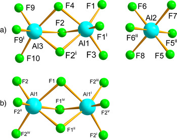
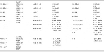
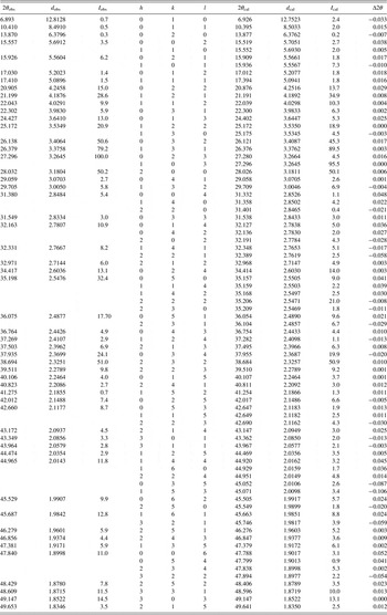
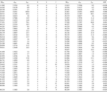
Atom numbering in AlF6 octahedra is shown in Figure 4, for both structures. Rietveld refinement details and selected geometric parameters are shown in Tables I and II, respectively, and the X-ray diffraction data are in Tables III and IV. For the atomic coordinates and more geometric parameters, see the supplementary material including the CIF files.
(Color online) Atom numbering in Al–F polyhedra. (a) Cs2AlF5, (b) Cs3Al2F9. Symmetry codes for Cs3AlF9: (i) −y, −x, −z + 1/2; (ii) −y, x − y, z; (iii) x, x − y, −z + 1/2; (iv) −x + y, −x, z; (v) −x + y, y, −z + 1/2; Cs2AlF5: (i) 1 − x, y, z; (ii) −x, y, z.

Selected interatomic and contact distances (Å) for Cs2AlF5 and Cs3Al2F9.

DFT-optimized values are in italics. Note that only the Cs···F contact distances <3.5 Å are considered.
(i) −y, −x, −z+1/2.
X-ray diffraction data for Cs2AlF5 at 22°C (CuK α1).

X-ray diffraction data for Cs3Al2F9 at 22°C (CuK α1).

B. Solid-state DFT structure optimization
As the accuracy of the resulting atomic coordinates is in both structures influenced by the presence of the heavy Cs atom and by poor ratios of the number of refined parameters to the number of structure factors, the structures were further optimized by energy minimization in the solid state, whose accuracy is comparable with that of single-crystal refinements. All the solid-state calculations were performed using the VASP code (Kresse and Hafner Reference Kresse and Hafner1993; Kresse and Furthmüller Reference Kresse and Furthmüller1996a, Reference Kresse and Furthmüllerb). To optimize the structures, a hybrid PBE0 functional (Perdew et al., Reference Perdew, Ernzerhof and Burke1996) was used. Plane waves formed a basis set and the calculations were performed using the projector-augmented wave method (Blöchl, Reference Blöchl1994; Kresse and Joubert, Reference Kresse and Joubert1999) and atomic pseudo-potentials (Kresse and Hafner, Reference Kresse and Hafner1994). The energy cutoff controlling the accuracy of structure optimization calculations was in both cases set to 700 eV and the Brillouin zones were sampled in four k-points. The positions of all 48 (Cs2AlF5) and 28 (Cs3Al2F9) atoms in the computational P1 cells were fully relaxed (i.e. without having imposed any restriction) while keeping the lattice parameters of the respective cells fixed at the values obtained from the diffraction data. Geometrical analysis of the optimized structures done by means of the PLATON program (Spek, Reference Spek2009) showed that the originally proposed space groups were correct.
Prior to optimization of the structures of the title compounds the accuracy of the DFT method was assessed by comparing an accurately experimentally determined crystal structure with that obtained by the solid-state theoretical approach. For this purpose a compound with similar chemical and structural compositions, α-CsAlF4 (Lösch and Hebecker Reference Lösch and Hebecker1979) was chosen. Its crystal structure solved from single-crystal data consists of triangle chains of interlinked AlF6 octahedra alternating with isolated Cs cations.
IV. DISCUSSION
A. Assessing accuracy
From comparison of the experimentally determined and the theoretically calculated geometry of the moieties in α-CsAlF4 it is seen (Table CAL, supplementary material) that the optimized solid-state calculation provides excellent agreement for the Al–F2 and Al–F3 bond distances and slightly overestimate the Al–F1 bond length, but all these differences are smaller than 2σ. Similarly, Cs–F bond and F···F contact distances are very close to the experimental values.
B. Crystal structures of Cs2AlF5 and Cs3Al2F9
The DFT-optimized geometry of face-sharing fluoroaluminate anion Al2F9 3− anion is in both structures in very good agreement with the experimentally determined geometry in [C18Mim]3[Al2F9](CH2Cl2)1.754 (C18MIm+ = 1-methyl-3-octadecylimidazolium cation) and also with molecular MP2/aug-cc-pVTZ calculations (Xu et al., Reference Xu, Matsumoto and Hagiwara2013). As the ionic radii of Al3+ and Fe3+ are close, the optimized bond angles in the anion are in both structures also close to those in Fe2F9 3− in Cs3Fe2F9 (Dance et al., Reference Dance, Mur, Darriet, Hagenmuller, Massa, Kummer and Babel1986). Calculated geometry of the isolated AlF6 octahedron in the structure of Cs2AlF5 is well-comparable with that of analogous octahedron in the structure of a hybrid fluoride solved from the X-ray single-crystal data (Adil et al., Reference Adil, Goreshnik, Courant, Dujardin, Leblanc and Maisonneuve2004). The Al–Al separations in Cs2AlF5 (2.709 Å) and Cs3Al2F9 (2.727 Å) are in line with the Al–Al distance [2.687 (2) Å] in the structure by Xu et al. (Reference Xu, Matsumoto and Hagiwara2013).
Most A
2
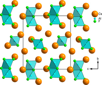
MF5 crystal structures (A = K, Rb, NH4; M = Fe, Cr, V, Ga) are characterized structurally by the presence of MF5 octahedral chains, either cis- or trans-linked. There are four forms for K2FeF5 (Le Bail, Reference Le Bail2013), two for (NH4)2FeF5 (Fourquet et al., Reference Fourquet, Le Bail, Duroy and Moron1989) showing a total of six different known ways of organizing such octahedral chains. It was thus a surprise to disclose the presence of the Al2F9
3− anion in Cs2AlF5 (Figure 5), this anion presence being confirmed in Cs3Al2F9, increasing to three the number of established crystal structures containing it. Indeed, face sharing is not rare for M ≠ Al since it occurs in all hexagonal perovskites AMF3 and elpasolites A
2
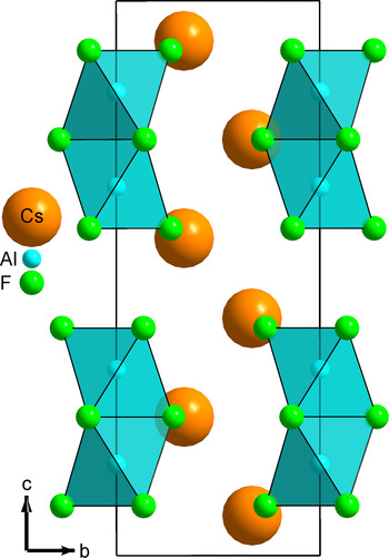
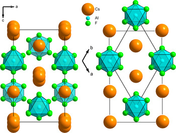
BMF6 (Massa and Babel, Reference Massa and Babel1988). This is especially frequent with A = Cs, and for instance, CsNiF3 is representative of the so-called 2L stacking type, 6L is observed for CsMnF3, 9L for the high-pressure form of CsNiF3 (etc.). Their hexagonal cell parameters have a in common (5.8 < a < 6.4 Å), c being the variable depending on the stacking sequence. Cs3Fe2F9 was described (Dance et al., Reference Dance, Mur, Darriet, Hagenmuller, Massa, Kummer and Babel1986) as a member of the series, being a cation-deficient variant of the CsNiF3 structure characterized by infinite chains of NiF6 face-sharing octahedra (Figure 6). The Cs2AlF5 structure projection onto the (ac)-plane allows us to conclude that it belongs to the same family as these hexagonal series when the relation c ~ a
 $\sqrt 3 $
with a = 6.36216 (17) Å, c = 11.4102 (3) Å (~11.02) evidence the pseudo-hexagonal distribution of the Cs atoms and AlF6 octahedra, making obvious the similarity with the Cs3Al2F9 structure (Figure 7). Consequently, the Cs2AlF5 structure is orthorhombic pseudo-B-centred.
(Color online) Projection along the short a-axis of the structure of Cs2AlF5 showing the isolated AlF6 octahedra and the face-sharing octahedra dimers Al2F9 3−.

(Color online) Projection of the Cs3Al2F9 structure along the a-axis, being a cation-deficient variant (1/3 lacking) of the CsNiF3 structure in which infinite chains of face-sharing octahedra extend along the c-axis.

(Color online) Projection of the Cs3Al2F9 structure along the hexagonal c-axis (right) compared with that of Cs2AlF5 along the b-axis (left), evidencing strong similarities. The face-sharing octahedra dimers and the Cs atoms are distributed in the same way in both the structures, and the isolated octahedra in Cs2AlF5 replace one of the Cs atoms at 1/3, 2/3, z-position in Cs3Al2F9.

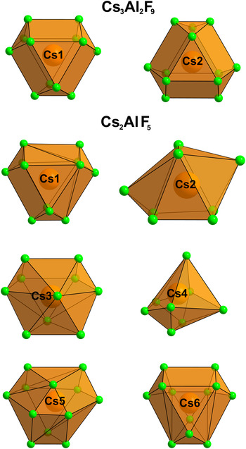
In Cs3Al2F9, both Cs atom-sites are 12-coordinated in anti-cuboctahedra. In Cs2AlF5, Cs1, and Cs6 adopt the same coordination and polyhedron, distorted, but the other Cs atoms are differently coordinated: the Cs2F8 polyhedron is a bicapped trigonal prism; the Cs3F10 polyhedron is a half-cuboctahedron with a 10th fluorine atom caping the other side of the hexagonal face; the Cs4F8 polyhedron is a pentagonal pyramid with two fluorine atoms caping the other side of the pentagonal face; Cs5F9 is a half-cuboctahedron, which would become a complete cuboctahedron if Cs–F distances were considered up to 3.8 Å (Figure 8).
(Color online) Cesium atom coordination polyhedra in Cs3Al2F9 and Cs2AlF5.

V. CONCLUSION
Five crystal structures have been now established in the AlF3–CsF system, α-, β-, γ-CsAlF4, Cs2AlF5, and Cs3Al2F9 so far, although their existence during the synthesis in the solid state, in totally anhydrous conditions, is not established. Four of them were determined from the powder diffraction data, of which three were solved ab initio and one was refined isostructurally with its Fe analog. No MF5 chain is observed in Cs2AlF5, which makes it an exception among the A 2 MF5 structure types. The Cs3AlF6, CsAl3F10, and the β′-CsAlF4 (Chen et al., Reference Chen, Cao and Zhang1997) crystal structures are still to be determined, as well as that of the thermal decomposition product of Cs2AlF5.
SUPPLEMENTARY MATERIAL
The supplementary material for this article can be found at http://www.journals.cambridge.org/PDJ
ACKNOWLEDGEMENTS
The authors thank U. Bentrup, H. Duroy, and J. L. Fourquet for providing the Cs2AlF5 and Cs3Al2F9 samples. DFT calculations were performed in the Computing Centre of the Slovak Academy of Sciences using supercomputing infrastructure acquired within the projects ITMS 26230120002 and 26210120002 (Slovak Infrastructure for High-Performance Computing) supported by the Research and Development Operational Programme funded by the ERDF.