Introduction
The demand for FSS remains high for shielding sensitive electronic equipment due to their low cost, compact profile, and ease of production. FSSs are periodic structures that manipulate electromagnetic waves based on parameters such as frequency, polarization, and angle of incidence [Reference Munk1]. A key type is the polarization-sensitive FSS, which selectively transmits or reflects electromagnetic waves depending on their polarization. For instance, in [Reference Zhu, Zhang, Zhang, Ge and GaoA2], an FSS was employed as a sub reflector, transmitting signals within the 31.7–36.3 GHz range under TE polarization while reflecting all incident waves across the Ka-band under TM polarization. In [Reference Xu, Zhou, Liu, Wang and Qian3], the FSS converts y-polarized incident waves into x-polarized waves within the 5.76–7.12 GHz passband and reflects x-polarized incident waves. Furthermore, an FSS [Reference Princy, Sreeja, Manikandan and Radha4] blocks specific frequencies under TE and TM polarization, demonstrating polarization-dependent frequency selectivity.
Although these polarization-sensitive FSSs provide selective frequency responses for TE and TM polarizations, their performance remains fixed after fabrication. To introduce adaptability in frequency selectivity, researchers have explored different tuning mechanisms, including mechanical, electrical, and material-based approaches. Mechanically tunable FSS [Reference Sivasamy, Moorthy, Kanagasabai, Samsingh and Alsath5] offer passive reconfigurability but suffer from slow tuning speeds, integration challenges, and limited tuning ranges. Meanwhile, electrically tunable FSS utilizing active components, such as PIN diodes [Reference Paiva, Neto and D’Assuncão6–Reference Güler, Keskin and Türker Tokan9] and varactor diodes [Reference Bai11, Reference Tian, Huang, Cheng, Liang, Shanrong, Yao, Guan, Yanlin and Liu12], provide fast switching capabilities but face challenges like high power consumption, complex biasing circuitry, and reliability issues, which reduce their suitability for large-scale implementations.
Beyond mechanical and electric methods, material-based tunability has also been explored. Graphene-based tunability [Reference Entesari and Saghati13] has the potential for high-speed operation but struggles with controlling surface conductivity, whereas liquid crystal-based FSS [Reference Huang, Zhang, Hu, Aqeeli and Alburaikan14] is easy to integrate but has limited tuning ranges. Microfluidic technology provides an effective alternative for achieving material-based tunability and overcoming certain limitations. By precisely controlling the flow of liquids within microchannels, the electromagnetic properties of a structure can be altered, enabling dynamic reconfiguration with low loss, high power handling, and a broader tuning range [Reference Chou, Ke, Lin and Lin15]. For example, researchers have achieved frequency reconfiguration utilizing liquid metal in patch antenna [Reference Song, Gao, Chui and Rahmat-Samii16], FSS [Reference Li, Liu, Ren, Meng and Song17], power divider [Reference Wang, Wang, Zhang, Xu and Shi18], and filter [Reference Pham and Sigmarsson19]. Although effective, liquid metal-based designs require complex actuation mechanisms and face issues such as stiction and oxidation.
In contrast, distilled water presents a simple, cost-effective, and environmentally friendly option. In microstrip monopole antenna [Reference Singh and Saavedra20], frequency reconfiguration is achieved by filling the channels symmetrically, while polarization reconfiguration is achieved by filling the channels asymmetrically. In [Reference Tang and Chen21], frequency tuning is achieved by inserting distilled water-filled PTFE tubes between the ground and the patch.
Microfluidic technology has significantly advanced various fields, yet its widespread adoption remains limited due to fabrication challenges. Previous research [Reference Wang, Wang, Zhang, Xu and Shi18, Reference Singh and Saavedra20] has shown that microchannels developed with PDMS benefit their transparency, biocompatibility, and ease of replication. However, PDMS has certain drawbacks: it tends to adsorb hydrophobic molecules onto its surface, leading to irreversible binding and impacting experimental accuracy. Furthermore, scaling up PDMS production is challenging due to labor-intensive processes, extended curing times, limited mechanical strength, and the difficulty of creating large, monolithic structures. The assembly of multiple PDMS layers is also complex and time-consuming [Reference van Meer, de Vries, Firth, van Weerd, Tertoolen, Karperien, Jonkheijm, Denning, IJzerman and Mummery22].
In contrast, CNC machining [Reference Li, Liu, Ren, Meng and Song17] created specific microstructures, such as Y-shaped and cross-shaped pillars. Despite its utility, CNC machining is a subtractive process, which results in high material waste and restricts the complexity of achievable geometries. A further limitation of this method is its cost and lengthy production times, particularly when intricate design adjustments are required.
To overcome these limitations, this work leverages additive manufacturing (AM) to fabricate the substrate with inbuilt cavities in one step, eliminating the long and complex conventional manufacturing process. AM has gained widespread adoption across health, science, and Engineering [Reference Alvarez-Braña, Etxebarria-Elezgarai, Ruiz de Larrinaga-Vicente, Benito-Lopez and Basabe-Desmonts23, Reference MacDonald24] as it enables the fabrication of solid structures layer by layer from a Computer-Aided Design (CAD) model without the need for masks [Reference Calignano25]. Unlike traditional methods that require separate machining for the substrate and fluidic channels [Reference Wang, Wang, Zhang, Xu and Shi18, Reference Singh and Saavedra20] or the addition of external microfluidic modules [Reference Song, Gao, Chui and Rahmat-Samii16, Reference Tang and Chen21], our approach enables the monolithic construction of microfluidic devices. This eliminates additional adhesion or bonding steps [Reference Beckwith, Borenstein and Velásquez-García26], enhancing manufacturing consistency and reducing assembly complexity. Furthermore, this method does not require post-processing steps such as sintering or chemical treatment, making it a flexible, low-cost, and environmentally friendly solution [Reference Allah, Eyebe and Domingue27, Reference Prince, Riley and Miller28].
This work presents a polarization-dependent, frequency-agile FSS using distilled water, eliminating the need for active components and bulky mechanical setups. The asymmetric unit cell geometry provides distinct responses for TE and TM polarizations, emphasizing its polarization-dependent nature. Frequency tuning is achieved by controlling the presence or absence of distilled water in cavities, which are integrated into the substrate using the FDM technique. Fluid flow within these cavities is regulated through peristaltic pumps. Three distinct operating states are analyzed, each modifying the effective dielectric constant based on the electric field distribution, thereby enabling precise frequency tuning.
Design and equivalent circuit model of the tunable FSS
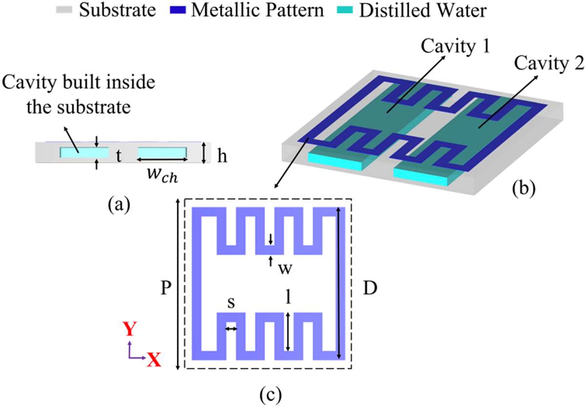
The unit cell geometry of the proposed FSS is shown in Fig. 1. The top metallic patch consists of a square loop with meandered vertical arms printed on the PLA dielectric substrate, which has a relative permittivity of ϵr = 2.57 and a loss tangent of  $\tan \delta$ = 0.02. Two rectangular cavities are vertically engraved within the substrate at locations of high electric field concentration. This strategic placement maximizes the influence of the fluid’s permittivity on the FSS resonant frequency, enabling effective tunability. Distilled water (ϵr = 78.4,
 $\tan \delta$ = 0.02) is used as the tuning medium.
Proposed unit cell geometry ( $P = 18, D = 16, s = 1, w = 1, l = 4, h = 1.6, t = 0.8$, wch = 5; units: mm): (a) side view, (b) isometric view, (c) metallic pattern in a unit cell.

The dielectric constant (ϵr) is an important parameter influencing polarization and dielectric behavior of materials when subjected to an electric field. This influence is described by the equation [Reference Tang and Chen21]
 \begin{equation}
D= \epsilon_{r_{\text{eff}}} \epsilon_0 E,
\end{equation}
where E is the electric field intensity, D is the electric flux density in a dielectric material,  $\epsilon_{r_{\text{eff}}}$ is the effective dielectric constant, and
 $\epsilon_{\text{0}}$ is the vacuum dielectric constant. Placing the cavities in regions of high electric field maximizes the impact of the fluid’s dielectric constant on the material’s behavior, leading to a larger change in effective permittivity
 $\epsilon_{r_{\text{eff}}}$. This increased influence shifts the resonant frequency to a lower value, enabling the desired frequency tuning. The effective permittivity
 $\epsilon_{r_{\text{eff}}} $ is calculated using the Maxwell-Garnett relationship [Reference Silavwe, Somjit and Robertson29] which represents the interaction between the filling medium (air or distilled water) and the dielectric material (PLA) comprising the cavity.
 \begin{equation} \frac{\epsilon_{r_{\text{eff}}} - \epsilon_{r_{\text{fill}}}}{\epsilon_{r_{\text{eff}}} + 2 \epsilon_{r_{\text{fill}}}} = f \frac{\epsilon_s - \epsilon_{r_{\text{fill}}}}{\epsilon_s + 2 \epsilon_{r_{\text{fill}}}}
\end{equation}
where  $\epsilon_{r_{\text{fill}}}$ represents the relative permittivity of the filling medium and ϵs represents the relative permittivity of the substrate and f is the fractional volume occupied by the dielectric comprising the two fluidic cavities.
TE polarization
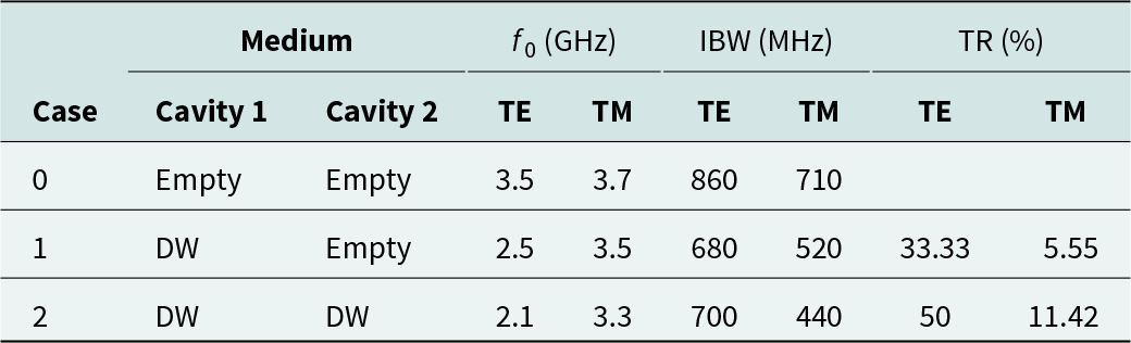
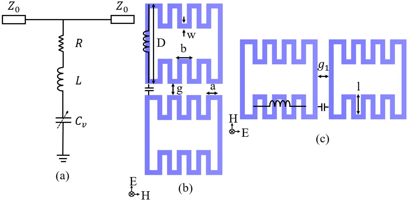
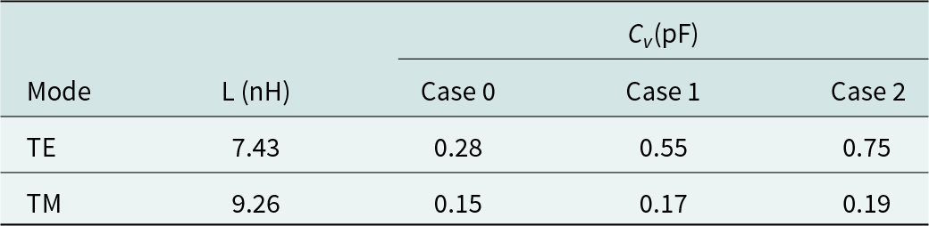
To understand the tuning mechanism of the proposed FSS under different operating states as shown in Table 1, an equivalent circuit model (ECM) is developed using ADS software. The proposed band stop FSS is modeled as a series RLCv circuit as illustrated in Fig. 2(a). The resonant frequency of the proposed band stop FSS is given by
 \begin{equation}
f_r = \frac {1}{2\pi\sqrt{L\ C_v\ }}
\end{equation}
Operating states of the proposed FSS

f 0: Center frequency, IBW: Impedance bandwidth, TR: Tunable range, DW: Distilled water.
(a) Equivalent circuit model (ECM) of the proposed FSS, mechanism of the proposed FSS under normal incidence for (b) TE polarization, (c) TM polarization (a = 3.6, h 1 = 10,  $f = 1, b = 3\ and\ g = 2$ (units: mm)).

where L and Cv represent the equivalent inductance and variable capacitance, respectively.
Fig. 2(b) shows the mechanism of the proposed FSS under normal incidence for TE polarization. The metallic strip is equivalent to inductance L and the gap between the unit cells is equivalent to capacitance Cv and the resistance R accounts for conductor, dielectric and fluid induced losses. The L and Cv can be calculated using the following equations (4) and (5) as discussed in [Reference Langley and Parker30–Reference Sarabandi and Behdad32],
 \begin{equation}
L = \mu_0 \frac{D}{2\pi} \ln\left(\csc\left(\frac{\pi w}{2D}\right)\right),
\end{equation}
 \begin{equation}
C_v = \epsilon_0 \epsilon_{r_{\text{eff}}} \frac{2D_1}{\pi} \ln\left(\csc\left(\frac{\pi g}{2D_1}\right)\right),
\end{equation}
where
 \begin{equation}
D_1= 4.a+4.b.
\end{equation}
The effect of the dielectric layer can be considered in the ECM by including the effective permittivity of the substrate in the capacitive component of the circuit [Reference Barrera and Carpes33]. The effective permittivity of the substrate  $\epsilon_{r_{\text{eff}}}$ is modified for the operating states Case 0, Case 1, and Case 2 by either filling or emptying the cavities with distilled water. This variation in effective permittivity alters the capacitance, leading to a shift in the resonant frequency. The values of
 $\epsilon_{r_{\text{eff}}}$ for these three distinct states are calculated using equation (2).
The capacitance Cv for Case 1 and Case 2 is calculated using equation (7) which includes parameters such as width w ch and height t of the cavity.
 \begin{equation}
C_v = \epsilon_0 \epsilon_{r_{\text{eff}}} \frac{2D_1 t}{\pi w_\text{ch}} \ln\left(\csc\left(\frac{\pi g}{2D_1}\right)\right).
\end{equation}
The inductance L and capacitance Cv for TE polarization under oblique incidence has been calculated using equations (8) and (9), with the function  $F(P,w,\lambda,\theta)$ and the correction factor
 $G(P,w,\lambda,\theta)$ computed as discussed in [Reference Murugasamy and Sivasamy35].
 \begin{equation}
\frac{\omega L}{Z_0}= \frac{D}{P}\cos\theta \times F(P,w,\lambda,\theta),
\end{equation}
 \begin{equation}
\frac{\omega C_v}{Y_0}= \frac{4D}{P}\sec\theta \times F(P,g,\lambda,\theta),
\end{equation}
where λ is the wavelength and θ is the angle of incidence. The function  $F(P,w,\lambda,\theta)$ defined in [Reference Murugasamy and Sivasamy35] has been modified for Case 1 and Case 2 to include the cavity dimensions t and w ch.
 \begin{equation}
F(P,w,\lambda,\theta)= \frac{Pt}{\lambda w_\text{ch}}\left[\ln\left(\csc\left(\frac{\pi w}{2P}\right)\right)+G(P,w,\lambda,\theta)\right].
\end{equation}
TM polarization
As shown in Fig. 2(c), under TM wave incidence, the meandered arms act as an inductance L, while the gaps between the vertical metallic strips create a capacitance Cv. These values are determined by substituting D, D 1, and g with D 3, D, and g 1, respectively in equations (4) and (5).
 \begin{equation}
D_3= 3.l,
\end{equation}
 \begin{equation}
\epsilon_{r_{\text{eff}}}=\left({\frac{1}{\left(\frac{f_{r_{\text{0,1,2}}}}{f_r}\right)^2}}\right) \epsilon_{r_{\text{eff0}}}.
\end{equation}
The effective permittivity  $\epsilon_{r_{\text{eff}}}$ for small perturbations causing only a small shift in resonant frequency is calculated using (12) which has been modified from [Reference Njogu, Sanz-Izquierdo, Chen and Parker34] to suit the proposed work. Here,
 $f_0, f_1, f_2$ represent the resonant frequencies for Case 0, Case 1, and Case 2 respectively, while fr denotes the resonant frequency of the FSS without cavities. The effective permittivity
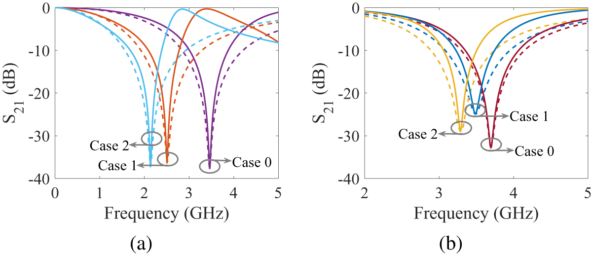
 $\epsilon_{r_{\text{eff0}}}$ is calculated for the scenario where cavities are not incorporated within the substrate [Reference Barrera and Carpes33]. Fig. 3(a) and (b) compare the EM simulated and circuit simulated S 21 curves, demonstrating good agreement for both TE and TM polarizations. However, an additional parasitic capacitance arises due to the fluidic channels, becoming more prominent when filled with distilled water [Reference Sepulveda, Cervantes and Saavedra36]. This is particularly under TE polarization, where the electric fields align parallel to the channels, resulting in greater insertion loss in the upper passband of the filter. Table 2 shows the ECM parameters of the proposed FSS. Further, under oblique incidence for TM polarization, the values of inductance L and capacitance Cv are calculated using equations (13) and (14).
 \begin{equation}
\frac{\omega L}{Z_0}= \frac{D_3}{P}\sec\theta \times F(P,w,\lambda,\theta),
\end{equation}
 \begin{equation}
\frac{\omega C_v}{Y_0}= \frac{4D}{P}\cos\theta \times F(P,g1,\lambda,\theta).
\end{equation}
Comparison of EM simulated and circuit simulated S 21 response for all the three cases under normal incidence for (a) TE polarization and (b) TM polarization (solid lines—simulation, dotted lines—ECM).

The ECM parameters of the proposed FSS

Simulation result and parametric analysis
The proposed FSS was designed and simulated in CST Microwave Studio. Due to its asymmetric design, the FSS exhibits polarization-sensitive behavior. Under TE polarization, the FSS with empty cavities demonstrates a band-stop characteristic centered at 3.5 GHz. The impedance bandwidth for TE polarization ranges from 3 to 3.86 GHz, while for TM polarization, it ranges from 3.35 to 4.06 GHz with a center frequency of 3.7 GHz.
Filling cavity 1 with distilled water causes the FSS to exhibit a band-stop response at 2.5 GHz under TE polarization, with an impedance bandwidth of 2.09 to 2.77 GHz. Under TM polarization, the band-stop response shifts to 3.5 GHz, with an impedance bandwidth of 3.22 to 3.74 GHz.
Filling both cavities with distilled water results in a band-stop response at 2.1 GHz for TE polarization, with an impedance bandwidth of 1.68 to 2.38 GHz. For TM polarization, the band-stop response occurs at 3.3 GHz with an impedance bandwidth of 3.06 to 3.50 GHz.
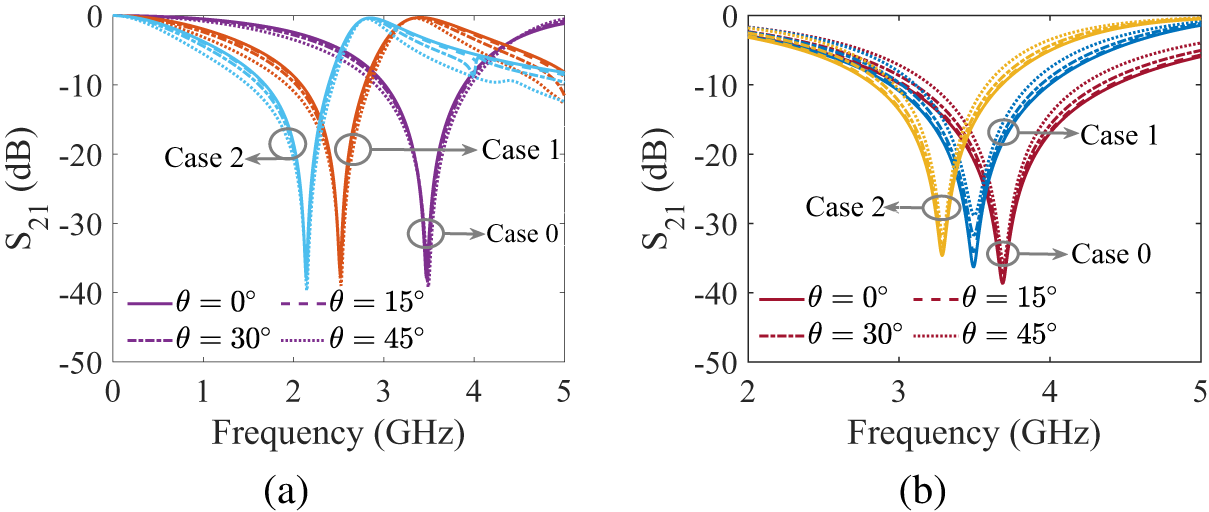
The angular stability of the proposed FSS under oblique incidence was investigated. The results, shown in Fig. 4(a) and (b) for TE and TM polarizations, respectively, indicate a stable S 21 response up to an incidence angle of 45∘.
Simulated S 21 response of the proposed FSS for all cases under oblique incidence for (a) TE polarization, (b) TM polarization.

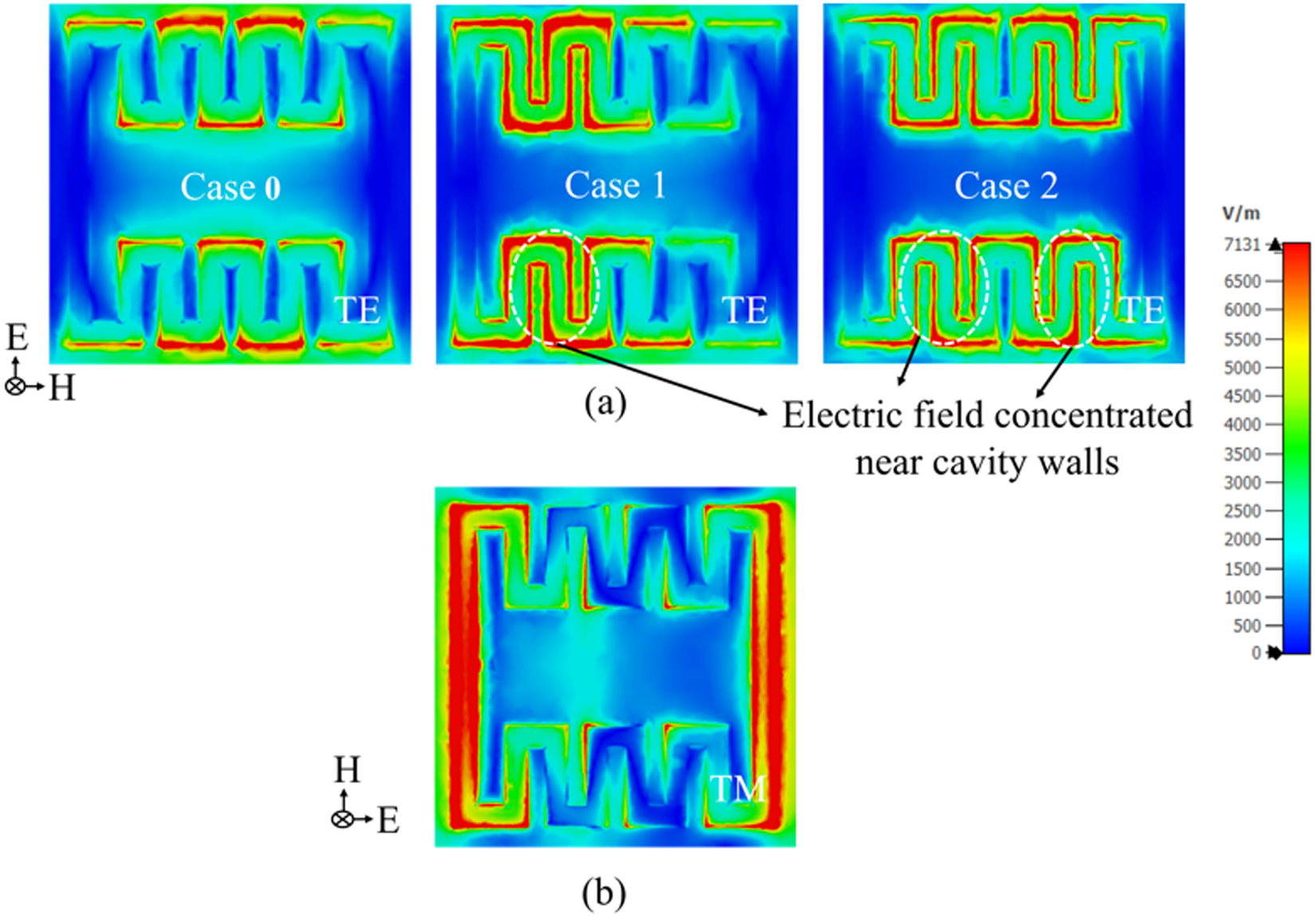
The electric field distribution of the proposed FSS under different operating states for TE polarization (incident wave along y direction) and TM polarization (incident wave along X direction) is shown in Fig. 5(a) and (b). For TE polarization, in Case 0, the electric field is highly concentrated along the meandered arms. In Case 1, however, the maximum electric field shifts toward the walls of cavity 1, which is filled with distilled water. For Case 2, the electric field is maximum around the walls of both cavities. Thus, the presence or absence of distilled water in the cavities alters the electric field distribution, thereby modifying the effective permittivity of the substrate. This change in effective permittivity affects the capacitance, causing the resonant frequency to shift to a lower value. However, for TM polarization, the electric field is concentrated along the vertical metallic strip for all cases. Since the cavities are not positioned in this high-field region, their interaction with the field remains minimal. As a result, the effective permittivity shows only a slight variation, leading to a small shift in the resonant frequency compared to TE polarization. Moreover, in TE mode, the upper passband for Case 1 and Case 2 is suppressed due to the strong coupling effect along the meandered metallic strips. This effect is intensified by the high electric field concentration in regions where the cavities are filled with distilled water.
Electric field distribution of the proposed FSS for all cases under normal incidence for (a) TE polarization, (b) TM polarization.

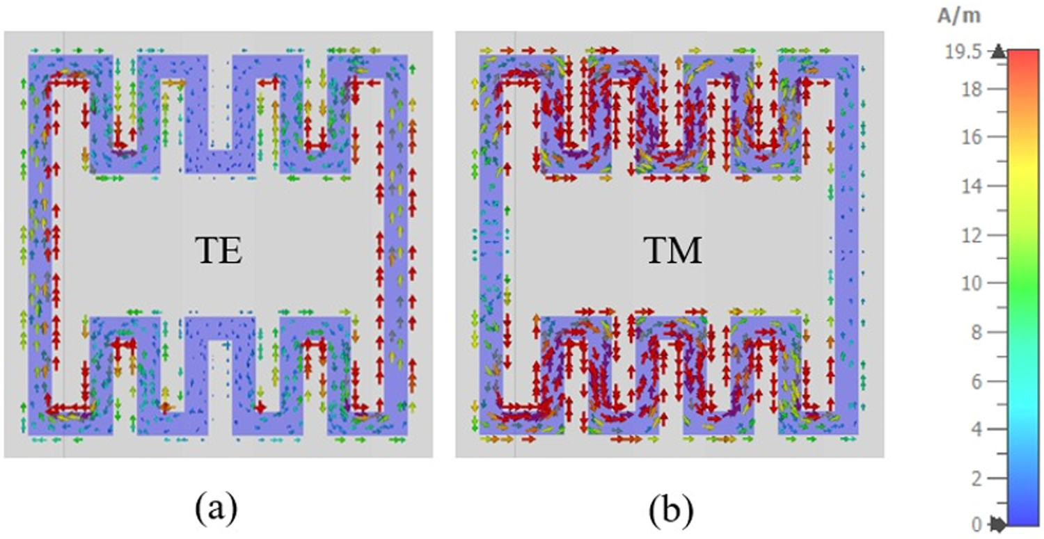
Fig. 6(a) and (b) illustrate the surface current distribution of the proposed FSS under normal incidence for TE and TM polarization. Under TE polarization, the surface current is primarily concentrated along the vertical strip, indicating a dominant current flow in that direction. Under TM polarization, the surface current is maximum along the meandered arms, which results in an increased effective inductance due to the extended current path along the meandered structure.
Surface current distribution of the proposed FSS under normal incidence for (a) TE polarization, (b) TM polarization.

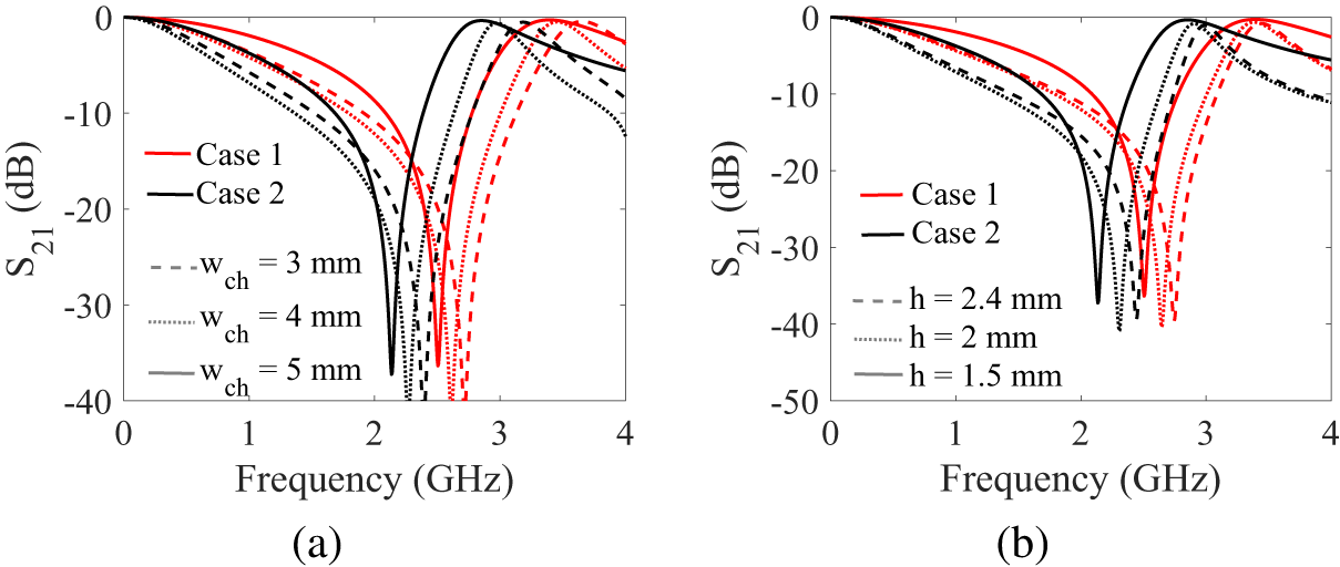
Fig. 7(a) shows the simulated S 21 response for TE polarization as a function of cavity width for Case 1 and Case 2. A larger cavity holds more distilled water, which raises the substrate’s effective permittivity and lowers the resonant frequency. Fig. 7(b) illustrates the simulated S 21 response for TE polarization as a function of substrate thickness (h) for Case 1 and Case 2. In these simulations, the cavity width (wch) and cavity thickness (t) were kept constant at 5 mm and 0.8 mm, respectively. Typically, increasing the substrate thickness lowers the resonant frequency. However, in this scenario, the simulation results show a rise in resonant frequency with greater substrate thickness. This behavior occurs due to a reduction in the effective permittivity of the substrate, which, as per Equation (2), results in an increased resonant frequency.
Simulated S 21 response under TE polarization for Case 1 and Case 2. (a) Varying the cavity width (wch). (b) Varying the thickness of the substrate (h) keeping the width wch = 5 mm and thickness t = 0.8 mm of the cavity constant.

Experimental validation
FSS fabrication
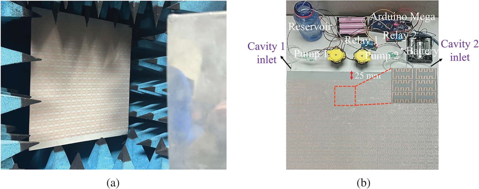
The proposed FSS is fabricated using the FDM 3D-printing technique. Fig. 8(a) and (b) shows the experimental setup and the pumping system of the proposed FSS. The initial design consists of a  $20 \times 20$ array of unit cells, with overall dimensions of 360 mm × 360 mm × 1.6 mm. To enable independent filling and draining of distilled water in cavities 1 and 2, vertical extensions of 25 mm have been added to the top and bottom of the substrate. These extensions are extended backward with a thickness of 2.5 mm, ensuring that cavity 1 is interconnected across all unit cells, and similarly, cavity 2 is interconnected across all unit cells. This modification provides dedicated inlets and outlets for both cavities, enabling efficient fluid management within the FSS. The metallic pattern was created by applying a copper compound aerosol spray with a conductivity of
 $5 \times 10^6$ S/m onto the substrate using a negative masking technique.
(a) Experimental setup and (b) pumping system.

Automated fluidic tuning system
Precise delivery of distilled water to the cavities was achieved using an automated pump-driven system with an Arduino and relay-controlled peristaltic pump. The Arduino program performed two filling operations: Case 1 involved filling cavity 1, while Case 2 involved filling both cavities simultaneously. Each cavity required 28.8 ml of distilled water, taking approximately 21.6 seconds.
The fluid removal process also takes approximately the same amount of time. However, to ensure complete drainage of fluid from the cavities, an additional waiting period of 5-10 seconds has been incorporated. This buffer time confirms that the channels are fully clear of fluid. Therefore, the switching time between different cases remains consistent, excluding this added buffer time. The exact waiting time can be adjusted based on specific structural and operational requirements.
Experimental setup and measurement
The S 21 response of the proposed FSS was measured using the free-space technique in an anechoic chamber. The measurement setup included a Vector Network Analyzer (Model: Microwave Site Master S820E), two horn antennas, and the FSS integrated with an automated fluidic system. The system was calibrated by first measuring the baseline S 21 without the FSS prototype, and then subtracted it from the S 21 obtained with the fabricated FSS prototype. The prototype was tested under all three distinct states for both TE and TM polarizations.
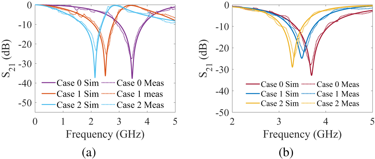
Fig. 9(a) and (b) shows the simulated and measured S 21 response of the proposed FSS for all three cases under normal incidence for TE and TM polarizations. In Case 0, the measured bandstop response was observed at 3.48 GHz for TE polarization and 3.68 GHz for TM polarization. In Case 1, where distilled water was introduced into cavity 1, the bandstop response shifted to 2.53 GHz for TE and 3.53 GHz for TM polarization. Finally, in Case 2, where both cavities were simultaneously filled with distilled water, the bandstop response shifted further to 2.15 GHz for TE and 3.32 GHz for TM polarization. The tuning range (TR) of the proposed FSS can be calculated using the following equation [Reference Huang, Shen, Feng and Li37]:
 \begin{equation}
TR (\%)= \frac{f_2 - f_1}{f_c} \times 100,
\end{equation}
Comparison of simulated and measured S 21 response of the proposed FSS under normal incidence for (a) TE polarization and (b) TM polarization.

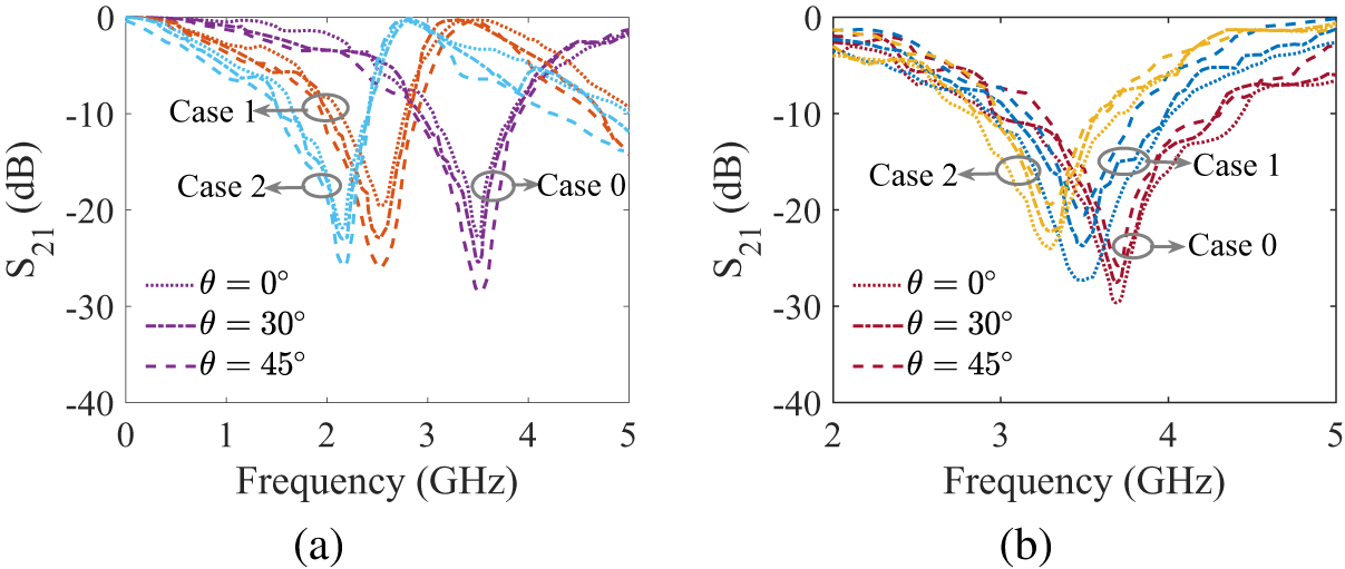
where f1 and f2 are lowest and highest resonant frequency of operation, and fc is the center frequency. The results indicate that the proposed FSS achieves a tuning range of 2.15-3.45 GHz, resulting in a 47.42% shift for TE polarization, and 3.32-3.68 GHz, resulting in a 10.28% shift for TM polarization. Furthermore, the proposed FSS was evaluated at oblique incidence angles of 0∘, 30∘, 45∘ for both TE and TM polarizations, as shown in Fig. 10(a) and (b). Minor discrepancies between simulation and measurement results can be attributed to fabrication imperfections and measurement uncertainties.
Measured S 21 response of the proposed FSS under oblique incidence for (a) TE polarization and (b) TM polarization.

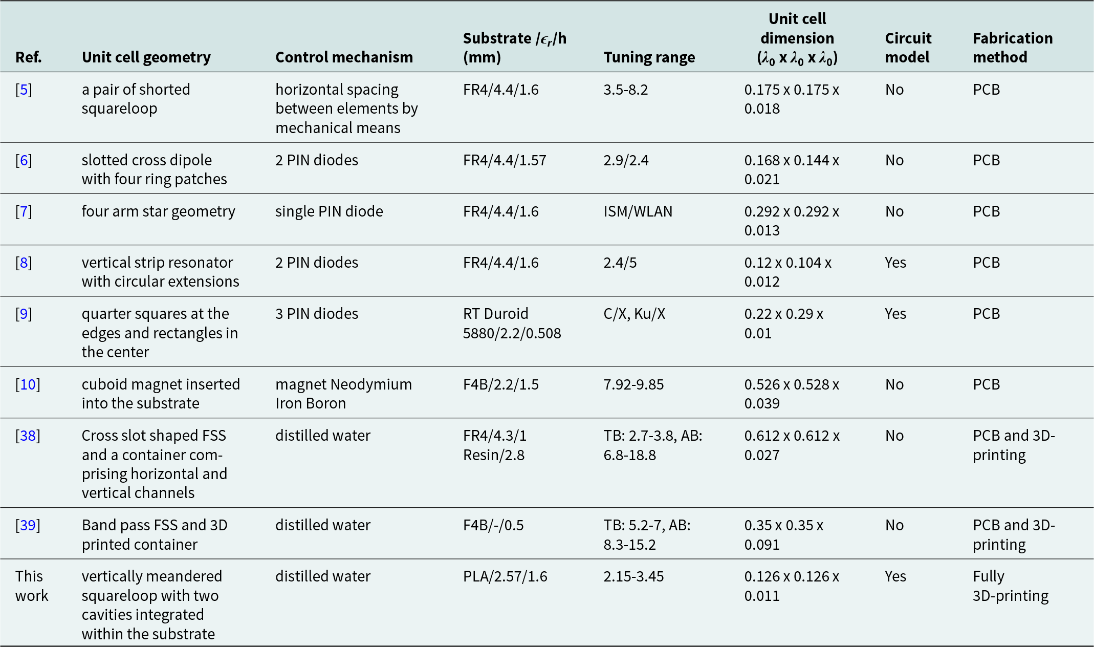
Table 3 presents a comparison between the proposed work and previous methods. Unlike traditional PCB-based subtractive fabrication [Reference Sivasamy, Moorthy, Kanagasabai, Samsingh and Alsath5–Reference Li, Wang, He, Yang, Chen, Hu and Yu10], the proposed work leveraged FDM-based 3D printing, allowing seamless integration of cavities within the substrate, which enhances design flexibility and simplifies fabrication. While previous approaches relied on active components [Reference Paiva, Neto and D’Assuncão6–Reference Güler, Keskin and Türker Tokan9], bulky mechanical setups [Reference Sivasamy, Moorthy, Kanagasabai, Samsingh and Alsath5], or electromagnetic tuning [Reference Li, Wang, He, Yang, Chen, Hu and Yu10] for frequency control, the proposed work employed distilled water as a passive, energy-efficient, and cost-effective tuning medium. The proposed FSS design is more compact than all other designs listed in Table 3, except [Reference Ali, Riaz, Kirmani, Khan and Shafique8], which is having only two switching states. Additionally, an equivalent circuit model was developed to examine the tuning mechanism and the impact of distilled water on effective permittivity and resonant frequency.
Comparison of the proposed work with previous works

TB: Transmission Band, AB: Absorption Band, λ 0: wavelength at lowest operating frequency.
Conclusion
This paper demonstrated a frequency-agile bandstop FSS using distilled water as a tuning medium. Frequency control is achieved by selectively filling the cavities in three distinct configurations. These cavities were integrated within the substrate using FDM, enhance practicality through simplified fabrication, compatibility, and scalability. Compared to traditional mechanical and electrical tuning methods, the proposed distilled water-based approach offers a reliable, environmentally friendly, cost-effective solution. Experimental validation under both normal and oblique incidence confirms the effectiveness of the proposed FSS. While the upper passband under TE polarization is relatively narrow, our focus in this work was on demonstrating fluidic tunability using distilled water. Bandwidth enhancement strategies will be explored in future studies. Moreover, the adoption of an asymmetric FSS geometry facilitated polarization selectivity, offering enhanced control over electromagnetic wave manipulation. This paves the way for significant advancements in adaptive communications systems, reconfigurable antennas, radar and sensing applications.
Acknowledgements
This work is supported by the Science and Engineering Research Board, India, under the grant CRG/2023/006435.
Data availability statement
No data was used for the research described in the article.
Competing interests
The authors declare that they have no known competing financial interests or personal relationships that could have appeared to influence the work reported in this paper.

J. Luke Carishma received her B.E. degree in Electronics and Communication Engineering from Rajalakshmi Engineering College, Chennai, Tamil Nadu, India, in 2016. She then obtained her M.E. degree in Wireless Technologies from Madras Institute of Technology, Chennai, Tamil Nadu, India, in 2018. Her professional experience includes working as an academician in the Department of Electronics and Communication Engineering at Dhanalakshmi Srinivasan College of Engineering, Coimbatore, Tamil Nadu, India, from 2019 to 2021. Following this, she served as a Project Associate at the National Institute of Technology, Tiruchirappalli, Tamil Nadu, India, for one and a half years on an ISRO-sponsored project. Currently, she is working as a Project Associate on a SERB-funded project and is simultaneously pursuing her Ph.D. at the National Institute of Technology, Tiruchirappalli, Tamil Nadu, India.Her primary research interests lie in the areas of additive manufacturing of tunable antennas and frequency-selective surfaces (FSSs).

Mettu Goutham Reddy received the B.Tech. degree from Sreenidhi Institute of Science and Technology, Hyderabad, India, in 2018, and the M.Tech degree in RF and Microwave engineering from Osmania University, Hyderabad, India, in 2020. He worked as Design engineer in Defence Laboratories and Research Laboratories, Hyderabad, India (DLRL-DRDO) for a period of six months. He is currently a Research Scholar with the Department of Electronics and Communication Engineering, National Institute of Technology, Tiruchirappalli, India. He has 7 research articles and 6 conference Proceedings. His current research interests include tunable Rf components, microwave integrated circuits, Substrate Integrated Wave Guide Components for RF and Millimeter Wave Applications. Mr. Goutham is a Graduate Student Member of the IEEE AP Society and the MTT Society.

Karthikeyan Sholampettai Subramanian received the Ph.D. degree from IIT Guwahati, India, in 2011. He has 13 years of educational activity and research experience in the area of RF and microwave. He was the Short-Term academic foreign visit U.K and France. He is currently Associate Professor with the Department of Electronics and Communication Engineering, National Institute of Technology, Tiruchirappalli, India. He has authored or co-authored more than 100 scientific research papers and technical reports. His current research interests include microwave integrated circuits, biological effects of microwaves, computer-aided design of MICS, metamaterials/frequency selective surfaces (FSSs), fractal antennas, MIC antennas, metamaterial antennas, and substrate-integrated waveguides. Dr. Karthikeyan is a Chair of the IEEE-APS Society Madras chapter. He is a member of the IEEE, IEEE MTTS, and IEEE AP-S. He is a Life Member of the ISTE.

Senthil Kumar Subramaniam received the B.E. degree in electrical and electronics engineering from Madurai Kamaraj University, Madurai, India, in 1999, the M.Tech. degree in electrical drives and control from Pondicherry University, Puducherry, India, in 2005, and the Ph.D. degree in electrical engineering from the National Institute of Technology, Tiruchirappalli, India, in 2013. He has 20 years of teaching experience at various engineering institutions. He is currently working as a Professor with the National Institute of Technology, Tiruchirappalli. He has extensively researched on self-excited induction generators for standalone and grid-connected applications. His current research interests include the development of new power converter topologies for renewable energy systems and intelligent transportation systems.