Introduction
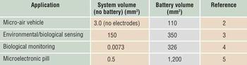
Electrochemical energy storage via batteries and electrochemical capacitors represents a key element in the global effort to divert energy usage from carbon-based fuels. While current electrochemical technologies are viable for energy storage applications such as powering of portable electronics, there is widespread agreement that improvements in electrochemical power sources are needed to meet future needs.Reference Goodenough, Abruña and Buchanan1 The inability of electrochemical power sources to meet current needs is already apparent in the field of microbatteries. Simply put, battery miniaturization has not kept pace with advances in CMOS electronics and the emergence of microelectromechanical systems (MEMS), which enable fabrication of autonomous microsystems for applications ranging from medical implants to sensing/actuation to communication. The sizes of these devices are often determined by the size of the power supply, and integrating the power supply within the device structure is not possible because of the small size of the device. Table I lists some battery-powered MEMS devices where the volume of the battery is many times larger than the device.Reference Sato, Berry, Casey, Lavella, Yao, VandenBrooks and Maharbiz2–Reference Johannessen, Wang, Cui, Tang, Ahmadian, Astaras, Reid, Yam, Murray, Flynn, Beaumont, Cumming and Cooper5
Survey of battery powered microelectromechanical systems.

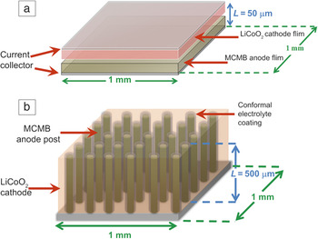
A key consideration for miniaturization, especially for integrated power, is the footprint area of the device. Traditional battery designs with 2D geometries need large footprint areas to achieve large capacities. This “real estate” requirement is particularly evident with thin-film microbatteries, such as lithium-ion thin-film batteries, which have limited areal capacities in the range of 0.5 mAhcm–2. Making electrodes thicker in order to store more energy is not a viable approach because the mechanical integrity of the film decreases with thickness (due to expansion and contraction of the active materials during cycling), but also because thicker films reduce the power density of the device.Reference Roberts, Johns, Owen, Brandell, Edstrom, El Enany, Guery, Golodnitsky, Lacey, Lecoeur, Mazor, Peled, Perre, Shaijumon, Simon and Taberna6 In general, 2D battery designs result in a compromise between energy density and power density because of the limitation in footprint area. With 3D battery architectures, one takes advantage of the third dimension, height, to increase the amount of electrode material within a given footprint area and thus increase the areal capacity. Such batteries are expected to achieve nearly 10 mAhcm–2.Reference Mazor, Golodnitsky, Burstein and Peled7 Equally important is that the anode and cathode arrangements for the battery are such that the power of the device is unaffected by the additional thickness. In this way, energy density and power density are effectively decoupled. A comparison between 2D and 3D battery configurations is shown in Figure 1, while various 3D architectures are presented in Figures 2and3.
Schematic of (a) a 2D parallel plate and (b) concentric tube 3D batteries. Typical dimensions for the different components are shown. L, battery stack height; MCMB, mesocarbon microbeads.

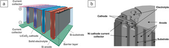
Schematic of 3D battery architectures that amplify the area of thin-film batteries: (a) use of a silicon trench substrate coated with a barrier layer to prevent any reactions of the substrate with Li-ions (Reprinted with permission from Reference Reference Notten, Roozeboom, Niessen and Baggetto12. ©2007, Wiley-VCH Verlag GmbH & Co.); (b) use of a perforated substrate of glass or silicon (Reprinted with permission from Reference Reference Nathan, Golodnitsky, Yufit, Strauss, Ripenbein, Shechtman, Menkin and Peled11. ©2005, IEEE).

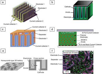
Schematic of 3D batteries based on 3D architectured electrode elements: (a) interdigitated rod electrodes (©2007, IEEE); (b) interdigitated plate electrodes (Reprinted with permission from Reference Reference Long, Dunn, Rolison and White14. ©2004, American Chemical Society); (c) concentric tube design; (d) inverse opal structure based on the 3D ordered macroporous carbon (3DOM-C) structure (Reprinted with permission from Reference Reference Ergang, Fierke, Wang, Smyrl and Stein16. ©2007, Electrochemical Society); (e) honeycomb-structured electrolyte (Reprinted with permission from Reference Reference Kotobuki, Suzuki, Munakata, Kanamura, Sato, Yamamoto and Yoshida17. ©2011, Elsevier); (f) aperiodic “sponge” design (Reprinted with permission from Reference Reference Long and Rolison18. ©2007, American Chemical Society).Reference Chamran, Yeh, Min, Dunn and Kim13, Reference Long, Dunn, Rolison and White14, Reference Ergang, Fierke, Wang, Smyrl and Stein16–Reference Long and Rolison18

The field of 3D batteries is poised for significant advances in the near future because of the development of a wide variety of synthesis techniques both for high-surface-area electrodes and for uniformly coating such electrodes with electrolyte layers that can function as separators. Little question remains that high surface area (i.e., nanostructured electrodes) can lead to rapid charging and discharging.Reference Whittingham8 High-surface-area electrodes pose significant design challenges, not only because unwanted side reactions that occur on electrode surfaces can be more significant as the surface area of the electrodes increases, but also because one of the key challenges remaining in the field of 3D batteries is the integration of the complementary electrode (if one begins the battery with a high surface area anode, for example, ultimately the integration of the cathode is a significant challenge). Incorporating this electrode within the 3D architecture often hinges on the structural integrity of the electrolyte and its conformality as methods and materials currently utilized for 2D planar architectures can result in irreversible damage to the electrolyte. This article will briefly review the current status of 3D batteries, including the different architectures and the general physical features of the electrodes and electrolytes required for various 3D configurations. Although relatively few results have been reported for actual batteries, the significant progress made on electrodes and electrolytes designed for 3D batteries is an indication that a number of these battery architectures will be successfully demonstrated within the next few years.
Three-dimensional microbattery designs
One characteristic feature of 3D battery architectures is that electrodes take on non-planar geometries, and transport between electrodes remains one-dimensional (or nearly so) at the microscopic level. The non-planar electrodes enable one to design electrode configurations that increase the energy density of the battery within the areal footprint by making use of the vertical dimension; a useful architectural metaphor is that these batteries build up (a skyscraper) rather than build out (single-level family house).Reference Dunn, Long and Rolison9, Reference Rolison, Long, Lytle, Fischer, Rhodes, McEvoy, Bourga and Lubers10 The comparison in Figure 1 between a conventional 2D parallel plate (a) and the 3D concentric tube (b) effectively visualizes the differences between the two basic configurations. Taking advantage of the vertical dimension enables the 3D battery to utilize more surface area, leading to higher power, while maintaining a small areal footprint. The energy density of the 3D battery is increased by simply increasing L, the length of the rods. Thus, neither small footprint area nor high power density is sacrificed. The ultimate value of L, however, will be limited due to ohmic resistance along the rods, with the optimized value being determined by a combination of parameters, including the electronic and ionic conductivity of the electrode materials, the ionic conductivity of the electrolyte, and electrode geometry.
A number of 3D microbattery designs have been proposed. While only a few have demonstrated complete cycling, nearly all have shown, in half-cell studies, that their 3D electrodes function effectively. One 3D battery approach involves amplifying the area of a thin-film battery (Figure 2). By using micromachining methods, holes or trenches of specific dimensions can be machined into glass or silicon to form a 3D substrate, thus increasing the surface area accordingly. The different battery components (current collectors, electrode materials, electrolyte) are then deposited conformally as thin films on the 3D substrate.Reference Nathan, Golodnitsky, Yufit, Strauss, Ripenbein, Shechtman, Menkin and Peled11, Reference Notten, Roozeboom, Niessen and Baggetto12 This design offers the advantage of extending thin-film deposition methods to the fabrication of 3D configurations and achieves a significant increase in energy density compared to thin films because of the area gain. The design, however, has considerable volume associated with the 3D substrate and, as is the case with thin-film batteries, the energy density is limited by the amount of active material that can be deposited.
Another 3D battery design uses the 3D architecture itself as the electrode element. This approach, which comprises the interdigitated and concentric arrangements, permits full utilization of the electrode volume. The configurations proposed by Chamran et al.Reference Chamran, Yeh, Min, Dunn and Kim13 and Long et al.Reference Long, Dunn, Rolison and White14 correspond to interdigitated rods or plates of each electrode, with the electrolyte filling the remaining volume (Figure 3a and 3b). There are two important considerations with this design approach. First, the energy density is directly related to the height of the rods or plates, which is limited because of the ohmic resistance of the element. To circumvent this height limitation, Simon’s group employed a nonplanar 3D current collector, upon which the battery components were successfully deposited conformally.Reference Taberna, Mitra, Poizot, Simon and Tarascon15 Second, in order to maximize energy density, the volume occupied by the electrolyte should be minimized. This criterion has made the development of conformal electrolytes a critical feature in the development of 3D battery technology. The concentric design (Figure 3c), originally proposed by Martin, leads to higher energy densities than the interdigitated configuration because it minimizes the volume used for the electrolyte.Reference Dunn, Long and Rolison9
Another example of a 3D architecture electrode is that of inverse opal structures (Figure 3d).Reference Ergang, Fierke, Wang, Smyrl and Stein16 In this case, templates are used to form a highly porous electrode structure with periodic porosity that can be coated by the other battery components. Conformal coatings are critical here also. Recently, Kotobuki et al. reported another 3D architecture approach in which a honeycomb structure with a bidirectional pore arrangement serves as the electrolyte (Figure 3e).Reference Kotobuki, Suzuki, Munakata, Kanamura, Sato, Yamamoto and Yoshida17 Electrode materials are then deposited in pores located on opposite sides of the electrolyte.
In contrast to the spatially ordered and periodic arrangements described, aperiodic designs have also been investigated. Rolison proposed a sponge topology that involves the use of a mesoporous aerogel upon which an electrolyte is deposited conformally (Figure 3f).Reference Long and Rolison18 A variation on this approach is to use a porous metal or carbon structure (mesh, foam, or sponge) as a current collector and then successively deposit the electrode material and polymer separator. In both of these aperiodic approaches, the other electrode material fills the remaining pores in the structure.
As indicated previously, the success of these 3D battery designs is highly dependent on the deposition of a thin, conformal, pinhole-free, and mechanically stable electrolyte film on the nonplanar electrode. Although a few 3D batteries have been demonstrated to date, no specific design has emerged as being optimal. At present, only electrodeposition has been effective at producing conformal coatings. It would seem that in order for 3D battery technology to become an important direction for energy storage, a variety of conformal deposition methods need to be established that involve a range of ionically conductive organic or inorganic materials.Reference Ergang, Fierke, Wang, Smyrl and Stein16, Reference Long and Rolison18
The interdigitated battery electrodes shown in Figure 3a can lead to non-uniform current distributions. Hart et al. used finite element analysis (FEA) to establish the relationship between current distribution and electrode arrangement for an electrode based on the interdigitated rod design.Reference Hart, White, Dunn and Rolison19 They found that the current distribution for an electrode composed of alternating anode/cathode rods within a row is more uniform than that of an electrode composed of parallel anode/cathode rows. Although a uniform current distribution is required to cycle a battery efficiently, the authors suggested that 3D designs that yield non-uniform current densities may be useful provided they are applied to battery chemistries that are kinetically slow. It is important to note that the current densities for the concentric tube and sponge architectures are uniform because of the 1D radial transport between anode and cathode.Reference Long, Dunn, Rolison and White14
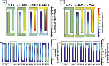
Another FEA-based study analyzed the current and voltage distribution for the “trench” design shown in Figure 2a. In this simulation study, Zadin et al. investigated how varying the electrode conductivity, plate length, and plate tip radius of curvature would affect the performance of a Li-ion battery composed of a graphite anode and a LiCoO2 cathode.Reference Zadin, Kasemägi, Aabloo and Brandell20 Results showed that even in electrodes of similar conductivities, lithium intercalation is non-uniform across the plates, and much of the electrochemical activity occurs at the electrode tips. Rounding the plate tip can distribute the current more evenly, and reducing the size of the plates creates a more uniform environment (Figure 4).
Li-ion concentration gradient during the discharge of a 3D battery: (a) in electrode materials (top) and electrolytes (bottom) when negative and positive conductivities are equal (1 Sm–1); (b) in electrode materials (top) and electrolytes (bottom) when the positive electrode is 0.01 Sm–1 and the negative electrode is 1 Sm–1.Reference Zadin, Kasemägi, Aabloo and Brandell20 Reprinted with permission from Reference Reference Zadin, Kasemägi, Aabloo and Brandell20. ©2010, Elsevier.

Architectured electrodes: The first step toward the fabrication of 3D batteries
Now that we have described the general architectures under development for 3D batteries, we will turn to the synthesis strategies to fabricate the electrode structures themselves. Very active research efforts on the synthesis and characterization of 3D electrode structures have yielded a number of half-cell studies, with, in most cases, these electrodes forming the design elements for a 3D battery. Table II provides representative results obtained for different types of 3D electrode half-cells as well as 3D batteries. Because these studies largely focus on proof-of-concept issues, the areal energy densities are much lower than what can ultimately be achieved.Reference Notten, Roozeboom, Niessen and Baggetto12, Reference Kotobuki, Suzuki, Munakata, Kanamura, Sato, Yamamoto and Yoshida17, Reference Nishizawa, Mukai, Kuwabata, Martin and Yoneyama21–Reference Chamran, Min, Dunn and Kim29 Another subject covered in a later section is the development of conformal electrolyte coatings. This topic has received much less attention than 3D electrodes but clearly will become an important direction for the future.
Advances reported on the synthesis of 3D electrodes and 3D batteries.

* SU-8, epoxy photoresist from Microchem Corp.; MCMB, mesocarbon microbeads; PPYDBS, dodecylbenzene sulfonate doped polypyrrole.
Vertically aligned electrode arrays
This type of 3D electrode comprises two general groups that can be identified on the basis of rod dimensions. Nanowire arrays, the first category, involve submicron-sized rods and generally are <500 nm in diameter. These arrays are deposited directly on a substrate that can function as a current collector. The second category is based on filling a micromachined mold by electrodeposition or colloidal processing of nanoparticles. Rod dimensions here are often >10 μm, and, in many cases, binders and conductive additives are required for electrochemical operation.
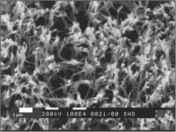
The studies by Martin and coworkers demonstrated that nanotube morphologies formed in the pores of porous alumina templates improved the capacity retention and rate capabilities of LiMn2O4 during cycling.Reference Nishizawa, Mukai, Kuwabata, Martin and Yoneyama21 This protocol stimulated an enormous amount of work using “template synthesis” as a means of synthesizing nanotubes, nanowires, and nanorods of different positive electrode materials.Reference Nishizawa, Mukai, Kuwabata, Martin and Yoneyama21, Reference Cheng, Tao, Liang and Chen30 Success with these materials led researchers to use the same strategy for negative electrode materials.Reference Wu, Chiang, Lee and Lin22, Reference Cui, Yang, Hsu and Cui23, Reference Park, Kang, Wang, Dou and Liu31–Reference Lan, Gao, Zhu, Zheng, Yan, Wu, Ringer and Song33 The results for SnO2 obtained by Li et al., shown in Figure 5, established the promise of using nanowires.Reference Li, Martin and Scrosati24, Reference Li and Martin34 Using a diameter of 110 nm and a packing density of 5×10⁸ nanowires cm–2, a capacity of 550 mAhg–1 was maintained for 1400 cycles at a rate of 58C (2.4 mAcm–2).34 This durability at high rate charge/discharge is in stark contrast to the rapid pulverization of 550 nm-thick electrodes of SnO2 observed after a few dozen cycles.
SnO2 nanowires prepared by the template synthesis approach.Reference Li and Martin34 Reprinted with permission from J. Power Sources 97-8, 240 (2001). ©2001, Elsevier.

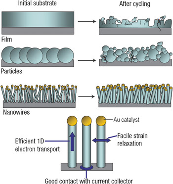
Because of improvements in capacity retention, nanowire arrays of Si-based materials as anodes have received considerable attention despite the fact that Si undergoes a 400% volume expansion upon lithiation.Reference Chan, Peng, Liu, McIlwrath, Zhang, Huggins and Cui35 The dramatic improvement in capacity retention exhibited by Si nanowires versus bulk Si is one of the success stories of nanostructuring electrode materials. There are now several reports in which nanowire arrays demonstrate improved performance over the bulk material because of the small diameter, spatial distribution, large aspect ratio, and good electrical contact inherent in the nanowires.Reference Cheng, Tao, Liang and Chen30, Reference Chen and Cheng36, Reference Bruce, Scrosati and Tarascon37 The nanoscale diameter has several beneficial effects on the performance of the array. First, the concentration polarization, which manifests itself as a concentration gradient of ions across the electrode-electrolyte interface and is caused by slow solid-state diffusion, is minimized, thereby increasing the useable capacity of the material. In bulk materials, unless extremely slow rates are used, the slow solid-state diffusion causes the concentration of Li-ions to be higher at the surface of an electrode than within the bulk of the electrode, causing some of the Li-ion capacity to be under-utilized. Second, short Li-ion diffusion path lengths improve the rate capabilities of the material during charge and discharge. Third, capacity retention improves because the nanoscale dimensions keep the absolute volume change relatively small, which reduces the mechanical strain that leads to structural degradation during cycling (see Figure 6).Reference Nishizawa, Mukai, Kuwabata, Martin and Yoneyama21, Reference Chan, Peng, Liu, McIlwrath, Zhang, Huggins and Cui35, Reference Che, Jirage, Fisher, Martin and Yoneyama38, Reference Winter and Besenhard39 What makes nanowires distinct from nanoparticles is that the spatial separation coupled with the large aspect ratio of the nanowires in an array permit the material to expand and contract radially without being physically constrained by binders and conductive additives, which are generally required when fabricating electrodes. In principle, nanowires can be used as electrodes upon which conformal electrolyte layers can be fabricated using methods such as electropolymerization (i.e., the electrodeposition of polymer layers onto the nanowires).
Schematic showing the influence of silicon morphology on the integrity of the electrode. Si nanowires effectively withstand the stresses associated with volume variation from Li cycling.Reference Chan, Peng, Liu, McIlwrath, Zhang, Huggins and Cui35 Reprinted with permission from Nature Nanotechnology. ©2008, Macmillan Publishers Ltd.

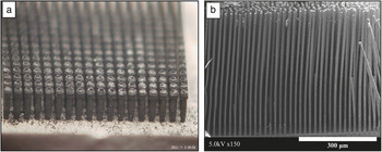
The second method for fabricating vertically aligned arrays utilizes silicon micromachining to create a sacrificial mold that can be used as an inverse template for the array structure. Dunn et al. have employed this method to create 3D electrodes of various materials, including vanadium oxide, mesocarbon microbeads (MCMB), and zinc (Figure 7).Reference Chamran, Yeh, Min, Dunn and Kim13, Reference Chamran, Min, Dunn and Kim29 This method is attractive because of the availability of well-established photolithographic and anisotropic etch technologies that enable the fabrication of high-aspect-ratio holes with spatial and dimensional precision. Battery electrode materials can be introduced into the mold through different methods. In the case of vanadium oxide and MCMB, an electrode slurry is extruded into the mold using a high-pressure syringe pump. Zinc and other metal arrays are prepared by electrodepositing the metal into the wells of the mold. In each instance, the silicon molds are then sacrificially etched to leave behind freestanding arrays. This fabrication method enables one to obtain 3D electrode arrays for different battery materials over a wide range of dimensions.
(a) Optical microscope image of freestanding arrays of mesocarbon microbeads; each rod is 100 μm in diameter and 550 μm in length. (b) Scanning electron microscopy image of freestanding zinc posts (5 μm in diameter, 550 μm in length).

Inverse opals and aerogels
The highly porous morphologies exhibited by the inverse opal and aerogel architectures are related in that they are porous in three dimensions (as opposed to typical nanowire geometries or MEMS architectures). The distinct difference is that the geometries presented by these architectures have the potential to be very flexible, which can help dissipate the stresses associated with electrode expansion and contraction. In addition, the aerogel architecture has the potential to be one of the highest power density architectures because of the enormous interfacial surface area.Reference Ergang, Fierke, Wang, Smyrl and Stein16, Reference Long and Rolison18 An advantage of both architectures, but especially aerogels, is that the pore sizes can be tuned from a few nm to the submicron range, which is critical for controlling the diffusion of monomer precursors into the structure and for optimizing the amount of the second electrode.
Electrolyte
The essential requirements for an optimized electrolyte in a 3D interdigitated or interpenetrating battery have been well characterized in a number of publications.Reference Long, Dunn, Rolison and White14, Reference Bruce, Scrosati and Tarascon37, Reference Rhodes, Long, Doescher, Dening and Rolison40, Reference Agrawal and Pandey41 Several requirements must be met in a 3D battery separator for full realization of the promised performance of the 3D architecture. In particular, the electrolyte must demonstrate sufficient dielectric performance (high dielectric strength, resistivity, very low leakage current) to electronically separate the electrodes and to allow operation under high fields. Further, the electrolyte must be sufficiently flexible to permit the requisite electrode expansions during lithiation and must allow for the reasonable transport of lithium ions.Reference Long, Dunn, Rolison and White14
On the basis of the first few demonstration experiments, the power density of a 3D battery will be limited by how quickly the lithium ions can diffuse through the electrolyte film. This potential drawback is a function of the film thickness and the diffusion coefficient for Li through the film.Reference Long, Dunn, Rolison and White14, Reference Bruce, Scrosati and Tarascon37, Reference Lee, Yabuuchi, Gallant, Chen, Kim, Hammond and Shao-Horn42, Reference Bohnke, Frand, Rezrazi, Rousselot and Truche43 Because diffusion time decreases with the square of the thickness, a 10-fold decrease in electrolyte thickness will decrease lithium diffusion time by a factor of 100. Therefore, for optimal power performance, the rate of lithium transport between the electrodes (within the electrolyte) must be as high as possible, resulting from a thin and ionically conductive electrolyte film. Electrically insulating polymer films, both ionically conducting (which we have referred to herein as simply “electrolytes”) and as separators that host a wet (or rather damp) electrolyte, provide a class of material that can meet these requirements.
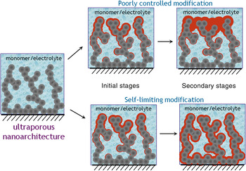
Several techniques are available for conformal deposition of thin insulating polymer films, including atomic layer deposition, solution casting, and self-limiting electropolymerization. Solution casting has been demonstrated in 3D batteries, with recent work (Figure 8) demonstrating the use of template-assisted casting as a route for coating poly(methyl methacrylate) on electrodeposited nanowires.Reference Notten, Roozeboom, Niessen and Baggetto12, Reference Gowda, Reddy, Shaijumon, Zhan, Ci and Ajayan44 The nanowires are deposited in an alumina template; the walls of the template are widened, opening space between the wires and the template walls; and the assembly is back filled with a polymer solution. However, self-limiting electrodeposition may provide a superior deposition technique for several reasons. Electrodeposition of electrically insulating films affords thin and conformal polymer coatings because the electrode becomes insulated as the redox-initiated polymerization occurs, leading to self-limiting behavior. That is, polymerization occurs more rapidly over bare electrode regions, which results in a complete, uniform modification of the conducting surface. Self-limiting electropolymerization further avoids the possibility of over-deposition at regions of higher potential, such as at the boundary surfaces of an aerogel (see Figure 9) or the tips of nanowires.Reference Long and Rolison18, Reference Rhodes, Long, Doescher, Fontanella and Rolison45
(a) Process flow diagram for the fabrication of a Ni–Sn/poly(methyl methacrylate) (PMMA) assembly using porous anodic aluminum oxide (AAO) as the template. (b) Transmission electron microscopy (TEM) image and cartoon showing the conformal coverage of the PMMA polymer onto the Ni-Sn nanowire; inset: higher magnification TEM image of a coated nanowire. Reprinted with permission from Reference Reference Gowda, Reddy, Shaijumon, Zhan, Ci and Ajayan44. ©2011, American Chemical Society.

Comparison of material deposition on a 3D substrate. With a poorly controlled deposition process, nonuniform films form while conformal films result with a self-limiting deposition process. Reprinted with permission from Reference Reference Long and Rolison18. ©2007, American Chemical Society.

Several groups have reported the electropolymerization of electrolyte designed for 3D battery structures. Rolison et al. reported electropolymerization of poly(phenylene oxide) and several derivatives that demonstrated conformal pinhole-free coatings with excellent dielectric properties.Reference Rhodes, Long, Doescher, Dening and Rolison40, Reference Rhodes, Long and Rolison46 Stein et al. utilized a similar approach in fabricating an inverse opal 3D battery structure.Reference Ergang, Fierke, Wang, Smyrl and Stein16 Owen et al. electropolymerized polyacrylonitrile (PAN) onto several substrates, including glassy carbon, nickel foam, and MnO2 cathode film to serve as the electrolyte.Reference El-Enany, Lacey, Johns and Owen47 The authors showed ionic conductivity of 10–2 Scm–1 with a plasticized film and cycled a full cell constructed from a MnO2 film coated by electropolymerization of PAN and contacted from the top with a lithium amalgam anode. These initial successes in the development of conformal electrolyte layers represent a critical step in the development of 3D battery technology. However a number of challenges regarding the electrolyte remain. For instance, due to the very high surface area of 3D battery electrodes, reactions occurring at the electrode/electrolyte interface could have a very significant effect on overall cell performance. The solid electrolyte interphase plays a critical role in liquid cells by stabilizing the electrode/electrolyte interfaces to electrochemical deterioration of the electrolyte. Analogous processes in a solid-state cell could lead to changes in Li-ion transport across the electrolyte or even failure of the dielectric properties. Another area requiring careful attention is the presence of pinholes in the electrolyte, which could lead to shorts and cell failure. One electrochemical method that can verify that the electrically insulating coating is uniform is the redox shutoff technique currently in use by numerous groups. This technique verifies that an electrode is uniformly passivated by an insulating polymer film through the “shutoff” of current passing from the electrode to a redox active permeant in solution. A question also remains as to the minimal thickness of electrolyte required for adequate electronic isolation of the electrodes under cycling of the cell. Rhodes et al. recently demonstrated that poly(phenylene oxide) electrosynthesized within birnessite-like MnO2 aerogels with a thickness of only a few nanometers left the 3D construction prone to shorting after filling with a nanoscale anode by in situ synthesis of RuO2.Reference Rhodes, Long, Pettigrew, Stroud and Rolison48
The final step: Integrating the other electrode by solution methods
Once the solid-state electrolyte has been coated conformally onto the 3D electrode (for example, an anode), the other electrode (i.e., the cathode), which will most likely be in the form of a particle-based slurry, needs to be added to complete the cell. A potential process flow for the concentric battery geometry is shown in Figure 10. Currently, there is little experience with this part of the 3D battery fabrication process. Thus, only general principles can be identified.
Schematic of the process flow for the fabrication of a 3D concentric battery from a nanowire array. Cathode incorporation at the final stage is a process that has received very limited study.

The slurry to be incorporated into the 3D structure has traditionally consisted of (1) an active cathode material in particulate form; (2) a polymer binder, the most commonly used is poly(vinylidene fluoride); (3) a particulate, carbon-based conducting additive to aid in improving electronic conductivity; and (4) a solvent that dissolves the polymer binder and provides a good homogeneous suspension of the active material and conductor. Several key aspects of the application process need to be considered when incorporating this slurry into a 3D cell. First, the slurry, through either its application or composition, must not damage the solid-state electrolyte. Thus, the application of this electrode to complete the cell must not induce defects or pinholes, thereby causing an internal short circuit that would result in a defective cell. The challenge here is that the solvent used in the slurry must wet the electrolyte but not dissolve it. To avoid causing damage to the solid-state electrolyte, one can consider the following protocol for determining the effect of the slurry composition of the solid-state electrolyte and the overall functionality of the 3D cell. This protocol consists of (1) determining the compatibility of the solvent with the solid-state electrolyte; (2) determining an appropriate binder based on the solvent; (3) ensuring the solution remains homogeneous during the application and curing process; and (4) ensuring that the cathode packing density is high so that there are no voids in the 3D cell structure.
From the previous list, the item of perhaps greatest concern is that there must be a high cathode packing density and that no voids (in the tens of microns range) occur in the 3D cell structure. Void spaces and low packing density can result in capacity mismatch and also reduce the performance of the cell due to increases in resistance to electron and ion transport. Two important properties that dictate packing density are the particulate size, both cathode and conductor, and slurry viscosity. Once the slurry properties are optimized, interdigitating the positive electrode into the 3D structure by traditional means such as through slot-die coating and/or dip-coating methods is feasible.
Summary
The field of 3D batteries is still very much an emerging area of research. The first steps toward developing the technology are extant, as a number of 3D battery structures have been identified, along with accompanying design rules to ensure that high energy and power densities are achieved within a small footprint area. A number of synthesis and electrode fabrication methods have been established, and, in many cases, their fine electrochemical performance indicates a promising future. A key feature, that of depositing conformal electrolyte films, has been demonstrated using electrodeposition, and other conformal deposition approaches are likely to be realized in the near future. Some of the remaining challenges that need to be addressed include electrode incorporation within the pore volume and battery assembly in general. There is little doubt that the technology for 3D batteries will continue to develop; there is a significant need for small footprint batteries, and 3D configurations offer high energy and power densities. While the initial efforts are directed toward autonomous power supplies for microscale devices, there is an interesting question of whether some of the designs are scalableReference Lytle, Wallace, Sassin, Barrow, Long, Dysart, Renninger, Saunders, Brandell and Rolison49 and offer advantages for other applications related to vehicles and grid storage.
Acknowledgments
A.L.P. acknowledges support from the NSF CAREER program (DMR-0956011) as well as the Semiconductor Research Corporation. B.D. acknowledges the financial support of the U.S. Office of Naval Research and the Defense Advanced Research Projects Agency.