



Introduction
Advances in ultrahigh frequency (UHF) radio frequency identification (RFID) technology have resulted in its use in numerous applications, such as object tracking (Apple AirTag), retailing (Walmart), payment transactions (banking), and transportation [Reference Chen, Yeh, Lin, Pan and Chang1–Reference Abdulghafor, Turaev, Almohamedh, Alabdan, Almutairi, Almutairi and Almotairi3]. To address public health challenges, such as the COVID-19 pandemic, small RFID tags have been used for monitoring human health in an efficient and noninvasive manner [Reference Occhiuzzi, Cippitelli and Marrocco4–Reference Ahmed, Le, Sydänheimo, Ukkonen and Björninen6]. However, if an RFID tag antenna is placed on or close to a human body, the electromagnetic absorption property of the human body, which has a varying dielectric constant ε r of 5.4–54.9, strongly influences the antenna’s behavior, effectiveness, and principal parameters, such as its input impedance, radiation efficiency, total gain, and operational frequency bands or bandwidth [Reference Alomainy, Hao and Davenport7–Reference Casula, Michel, Nepa, Montisci and Mazzarella9]. Several studies have proposed design techniques for overcoming these obstacles and enhancing the performance of tags near humans. In [Reference Aslam, Kashif, Amin and Tenhunen10–Reference Svanda and Polivka12], conventional patch antennas were proposed to improve the tag’s gain and radiation efficiency. These antennas comprise a radiating patch with an exciter slot or loop on the top and a ground plane at the bottom. The ground plane is used as an electric shield that decreases radiation absorption by the human body [Reference Svanda and Polivka13, Reference Björninen14]. However, the aforementioned antennas require the dimensions of the radiator to be approximately half the wavelength of the operational frequency. Therefore, these devices are typically large and therefore unsuitable for wearable devices that require a compact or low-profile tag.
To increase the gain of wearable tag antennas, many designs, including artificial magnetic conductors (AMCs), have been proposed [Reference Chiu and Hong15, Reference Hadarig, de Cos and Las-Heras16]. Specifically, an AMC contains a radiating bowtie-shaped or modified dipole (meander dipole) structure on its top, AMC unit cells inserted in its middle layers, and a backplane as a ground plane at its bottom to optimize antenna radiation and minimize interference. This design achieves considerably improved gain (up to 3–9 dBi) and can maintain its radiation pattern when placed on a human wrist. Moreover, the bandwidth for the reflection phase in the interval (−90°, 90°) increased from 4.7% to 7.3%. However, AMC tag antennas still have complex layouts, are large, and are expensive.
The inverted-F antenna (IFA) or planar IFA is a platform-tolerant design that was developed to reduce the size of tag antennas by including shorting pins or plates that create a short circuit between the top radiating plates and the ground plane [Reference Lin, Saito, Takahashi and Ito17–Reference Le, Ahmed, Ukkonen and Björninen21]. However, the miniaturization of the antenna configuration in this design results in a small bandwidth and poor efficiency. A contrasting design of electrically small antennas without shorting pins or shorting plates may achieve high radiation efficiency [Reference Luo, Gil and Fernández-García22–Reference Bouhassoune, Saadane and Minaoui25]. However, this configuration requires the tags to be mounted on clothing or gloves to reduce human body signal absorption. Some studies have produced reduced-size tag antennas by using helical antenna structures or nested-slot, suspended-patch antennas [Reference Lopez-Soriano and Parron26, Reference Marrocco27]; however, these designs are limited by their short read range (2.5 m), their narrow bandwidth, and the requirementto have a gap between the tag and the body. Moreover, the miniaturization of the antenna structure can be effortlessly achieved by using the collocated slots or monopole-slot [Reference Li, Zhang, Zheng and Feng28–Reference Li, Zhang, Zheng and Feng30]. However, when they are placed on objects that absorb electromagnetic field radiation (e.g. human body), maintaining the desired performance is a challenging task, given the organ layers and their associated composition dielectric constants. In the present study, a novel miniaturized tag antenna with a simple configuration, low profile, and wide bandwidth that can be mounted directly on a human body was designed. The proposed design is easily controlled by coarsely adjusting the positions of vias and fine-tuning the length or width of its coupled patches to achieve conjugate impedance matching with a Monza-4 tag chip. The designed tag antenna can be used for the identification and tracking of patients inside hospitals or quarantine areas to improve health-care quality and safety.
The original contributions of this study can be summarized as follows.
(1) A new design of a low-profile, three-dimensional (3D) dipole tag antenna was developed for application on various positions on the human body. The proposed tag configuration was not only miniaturized but also achieved a longer stable reading distance than those achieved by many other advanced tag antennas.
(2) A new design technique (3D dipole antenna [3DDA]) was achieved by effectively lengthening the resonant current distribution paths from the patches on the top of the device to the bottom of the device without increasing the antenna size.
(3) For conventional tag antennas placed on the human body, simultaneously optimizing the realized gain and bandwidth is challenging because of variations in the body composition of humans and the radiation absorption of the human body. However, the proposed 3DDA structure achieves considerably higher realized gain and a wider bandwidth than do conventional tag antennas. Moreover, with an impedance bandwidth of 69 MHz (7.54%) for a 3-dB return loss, the proposed tag can be applied in multiple RFID frequency ranges (North America, Europe, and Japan).
(4) Through the coarse-adjustment and fine-tuning mechanisms of the antenna impedance, matching with the microchip complex impedance can be easily achieved by controlling the positions of vias and the small gap of the coupled patches without using external matching networks.
(5) The designed tag achieves stable read detection regardless of its position on the human body (arm, chest, back, shoulder, or leg).
Antenna configuration and optimization
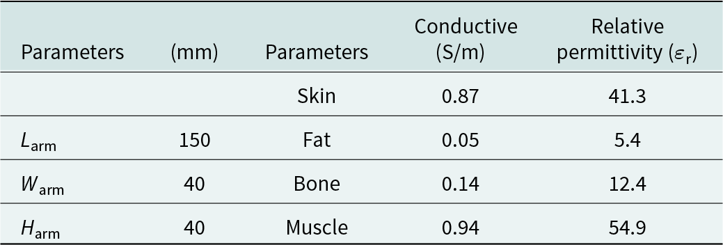
Figure 1 presents the configuration of a miniaturized tag antenna mounted on the human wrist. The miniaturized antenna (with dimensions of 40 × 20 × 1.6 mm3) was optimized using one FR4 substrate (thickness of 1.6 mm, dielectric loss tangent of 0.02, and relative permittivity of 4.4) with a rectangular patch in the middle and two additional patches closely coupled to its radiating edges. Four shorting pins (radius of 0.7 mm) were loaded at each end of the rectangular radiating plate and the two coupled patches to produce a 3D dipole current flow distribution through the top radiating plane to the ground or to lengthen the resonant current path length for considerably reducing the overall dimensions of the antenna. Moreover, by controlling the positions of the vias (L S1, L S2, L S3, and L S3) and the width of the coupled patches (W p1 and W p2), or small gap (W g), the inductance of the proposed antenna can be increased or decreased to achieve perfect matching with the conjugated impedance of the microchip. The Impinj Monza-4 microchip was used in the simulation calculations and measurements of this study. According to the manufacturer’s datasheet for this chip, the input excitation port of the chip has an impedance of 4.9−j70 Ω, and the chip has a minimum threshold power of −16.9 dBm at an operation frequency of 915 MHz. Critically, this datasheet indicates that various input impedance values can be selected to design an appropriate antenna structure. However, to optimize the design, an input impedance of 7.17−j74.22 Ω was selected for the Monza-4 microchip in this study. The measurements of the actual impedance of the chip are described in the following section. The chip was also configured with a shunted-port connection to facilitate soldering between the integrated circuit chip and antenna; thus, the RF1+ and RF2+ input pads (for antennas 1 and 2) could be shorted with the RF1− and RF2− input pads, respectively, during fabrication [31]. Table 1 lists the dimensions of the proposed tag antenna. The tag was attached to a four-layer model of the human wrist, whose electrical parameters are listed in Table 2. Figure 2 presents photographs of the proposed antenna prototype.
Geometry and dimensions of the proposed antenna with four shorting pins mounted on the human wrist: (a) front view; (b) side view of FR4 substrate and human wrist; and (c) back view of the antenna.

Dimensions of the proposed tag antenna

Dimensions and conductivity parameters of the adopted human wrist model
(a) Fabricated tag antenna mounted on a human wrist; (b) measurement of the antenna dimensions; and (c) comparison of the fabricated antenna with two commercial RFID tag products.

Most commercial tag antennas have dipole designs because of the simplicity and easy fabrication of such designs. In the present study, the required resonant feeding structure (open-slot exciter) had to excite the ground plane of the radiator. Furthermore, the length of the ground plane controlled the resonant frequencies and antenna gain. The optimized parameters of the proposed antenna that were obtained using Ansys HFSS version 14 are presented in Table 1.
Input impedance and sensitivity measurement of the adopted RFID chip
The input impedance of the Monza-4 chip (Z c = R c − jX c) varies with the frequency and strongly affects the performance of the tag antenna. The complex impedance of the microchip should be measured before the antenna is designed [Reference Nguyen, Lin, Chen, Chang and Chen32, Reference Nguyen, Lin, Chang, Chen and Chen33]. Measurements were performed using a time-domain reflectometer (TDR) balance probe connected to the SMA (Sub Miniature Version A) of a vector network analyzer (VNA), which had a frequency range of 0.8–1.0 GHz. The TDR probe was supported by an EZ-Holder to determine the minimum input power sensitivity, input resistance, and reactance of the Monza-4 chip by observing the corresponding fixed marker on the Smith chart. Furthermore, the probe was calibrated using a TDR calibration substrate with open, short, and load circuits before determining whether the pointer position deviated from the established standard [Fig. 3(a)]. In detail, the Monza-4 chip measurements were performed as follows:
Measurement system for determining the input impedance and sensitivity of the microchip.

• Step 1: The required standard probe was performed using the TDR calibration substrate. The balun probe was touched to no copper pads on the TDR substrate for the first measurement. Next, the probe was sequentially touched to the short and through pads on the calibration substrate. Finally, the balun probe was put in contact with to the three load pads, which had an equivalent resistance value of approximately 28, 50, or 75 Ω on the calibration substrate [Fig. 3(b)].
• Step 2: To obtain the power sensitivity of the Monza-4 chip, the calibrated probe was first fixed at every pad end [Fig. 3(c)]. Exciting power was then provided from −20 to 2 dBm in steps of 0.5 dBm in the frequency range of 0.8–1.0 GHz. A sudden change in the resistance and reactance indicated that the chip had been activated. The lowest starting power required to activate the chip was −16 dBm [Fig. 4(a)].
• Step 3: Finally, the input power was fixed as −16 dBm. The changes in the resistance and reactance of the Monza-4 chip with changes in the frequency between 800 and 1000 MHz were determined [Fig. 4(b)]. In particular, the measured input impedance at 915 MHz was Z c = 7.17–j74.22 Ω. A small deviation was observed between the measured values and those from the manufacturer’s datasheet; the measured values were used in the design optimization and evaluation described in the next section.
Monza-4 chip measurement results: (a) power threshold to activate the microchip and (b) input impedance.

Design analysis and 3d dipole antenna current distribution
Three fundamental considerations that markedly affect the performance of a low-profile tag antenna are the radiation efficiency and gain, the bandwidth, and the conjugated impedance matching between the antenna and the microchip. The bandwidth of a tag antenna can be increased using a lossy substrate as the backing metal or a multimode antenna structure [Reference Zhang and Long34]. However, such designs reduce the antenna gain, and exciting the desired modes is difficult because of the miniaturization of these designs [Reference Fante35]. The radiation efficiency, gain, and impedance match can be improved by loading parasitic elements between the top radiator and the ground plate; however, avoiding current cancellation is difficult in a small device [Reference Abdulhadi and Abhari36]. Because of these challenges, an antenna’s design should be optimized to obtain an appropriate balance between gain, bandwidth, miniaturization, and impedance matching. Moreover, the short wavelengths of a far-field RFID system are drastically attenuated by the variations in human wrist composition, which results in a decreased read range [Reference Chen37]. Therefore, a design technique based on the 3DDA current distribution is proposed. For all designs, the tag antenna was assumed to be attached to a human wrist with dimensions 150 × 40 × 40 mm3.
First, an initial configuration was considered that had no connections to shorting pins, a separated rectangular patch in the middle, and two additional rectangular patches that were directly coupled to the radiating edges with a small gap (W g) [Fig. 5(a)]. The first configuration exhibits matching impedance to the Monza-4 chip at 3.1 GHz [see Fig. 5(b)], which exceeds the desired UHF RFID band (860–960 MHz). In this case, the resonance path length was calculated using the following equation:
Tag antenna without shorting pins attached to the human wrist: (a) current density distribution, (b) matching impedance of the antenna at 3.1 GHz, and (c) gain and radiation efficiency at 915 MHz.

 \begin{equation}{{\textrm{L}}_{\textrm{1}}}{\textrm{ = }}{{\textrm{L}}_{\textrm{a}}}{\textrm{ + 2}}{{\textrm{W}}_{\textrm{e}}}.\end{equation}
The matching frequency of this first design can be approximated using (1), with L 1 = 41.4 mm (≈λ 0/8). Furthermore, the obtained gain and radiation efficiency were −19 dB and 3 × 10⁻¹%, respectively, which are insufficient for improving the read range of the tag antenna. This result was attributed to the majority of the radiation being produced around the middle rectangular patch; the two coupled patches were nearly nonradiating, as indicated by the plot in Fig. 5. To excite the additional coupled nonradiating patches, two shorting pins (via 3 and via 4) with a radius of 0.7 mm were loaded at each patch end [see Fig. 6(a)]. The antenna resonance frequency was further reduced to 1.8 GHz [Fig. 6(b)], and the resonating path length in this configuration was calculated using the following equation:
 \begin{equation}{{\textrm{L}}_{\textrm{2}}}{\textrm{ = }}{{\textrm{L}}_{\textrm{a}}}{\textrm{ + 2}}{{\textrm{W}}_{\textrm{e}}}{\textrm{ + }}{{\textrm{L}}_{\textrm{a}}}{\textrm{/2 + }}{{\textrm{L}}_{\textrm{a}}}{\textrm{/2 = 2}}\left( {{{\textrm{L}}_{\textrm{a}}}{\textrm{ + }}{{\textrm{W}}_{\textrm{e}}}} \right).\end{equation}
Tag antenna with two shorting pins loaded on each end of the coupled patches attached to the human wrist: (a) current density distribution, (b) antenna matching impedance at 1.8 GHz, and (c) gain and radiation efficiency at 915 MHz.

The matching frequency in the second design can be approximated using (2), with L 2 = 81.4 mm (≈λ 0/4). By including the excited coupled patches, the radiation efficiency and gain increased by approximately 2.3% and −12.3 dB, respectively. Moreover, for further reducing the profile of the antenna, two other shorting pins (radius = 0.7 mm) were inserted at each end of the radiating middle rectangular patch [Fig. 7(a)]. This step caused the matching frequency to shift from 1.8 GHz to 915 MHz [Fig. 7(b)]. By applying the aforementioned four shorting pins to each end of the patches, a 3DDA current distribution was produced [Fig. 7(a)]. In this case, the resonating path length was calculated as follows:
 \begin{equation}{L_{\textrm{D}}} = \sum \limits_{i = 1}^6 {I_i} + \sum \limits_{k = 1}^6 {J_k} + 4h.\end{equation}
Tag antenna with four shorting pins loaded on each end of the coupled patches and the middle rectangular patch attached to the human wrist: (a) formation of the 3DDA current flowing from the top radiator to the ground plane, current directions on the (1) top and (2) bottom of the antenna and (3) 3D view of the 3DDA current directions; (b) antenna matching impedance at 915 MHz; and (c) gain and radiation efficiency at 915 MHz.

The matching frequency in the optimized design can be approximated using (3). The total 3D dipole resonant current path length (L D) was 196.4 mm (≈0.6λ 0) at 915 MHZ, which allowed the antenna size to be reduced by approximately 80% compared with the size of conventional dipole antennas. Moreover, the 3D dipole current distribution produced by loading the four shorting pins enhanced the radiation efficiency and gain by approximately 25% and −2.8 dB, respectively [Fig. 7(c)].
Parameter evaluation of the tag antenna
The properties of the proposed tag antenna, namely input impedance, return loss, power transmission coefficient (PTC), radiation efficiency, and gain, were investigated through simulation to evaluate the effects of the design parameters on the reading distance of the tag. In Fig. 7(a), the highest current concentrations are observed around the vias, which suggests that the vias are useful for controlling the resistance and reactance or for coarse-tuning the proposed antenna. In addition, the relatively low current distribution densities along the edges of the coupled patches (near the central radiating patch) indicate that fine-tuning can be achieved by changing the width of the small gaps. The fundamental variables of the proposed antenna include the positions of the shorting pins (L S1, L S2, L S3, and L S4), the width of the small gaps (W g), and the length and width of the human wrist (L arm and W arm). In all evaluations, the proposed tag antenna was fixed at the middle of a human wrist with a size of 150 × 40 × 40 mm3. The effects of shorting pin 1 (via 1) and shorting pin 3 (via 3) were first evaluated (Fig. 8). Because of the symmetrical structure of the antenna, shorting vias 2 and 4 produced similar results to shorting vias 1 and 3. As highlighted in Fig. 8(a), the resistance and reactance changed as the position of shorting via 1 was changed as mm ≤ L S1 ≤ 9.7 mm if the operating frequency of the proposed antenna was fixed as 915 MHz. The inductive resistance of the tag antenna increased linearly from 70 to 82.1 Ω as L S1 was increased from 4.0 to 6.8 mm; however, the resistance only varied marginally between 7.8 and 8.8 Ω. By contrast, the inductive resistance of the configured antenna with via 3 shorted did not vary substantially with L S3 in the range of 2.8–5.7 mm; however, the resistance declined linearly from 8.2 to 4.9 Ω (Fig. 8(b)). These results indicate that impedance matching between the antenna and the microchip can be achieved by coarse-tuning the locations of shorting vias 1 and 3. Figure 8(b) and (c) clearly reveal that the reflection coefficient and PTC of the tag are sensitive to the positions of the aforementioned vias.
Effect of varying the positions of the two shorting pins (vias 1 and 3). Impedance with various positions of (a) via 1 and (b) via 3; (c) return loss with various positions of via 1 and via 3; and (d) PTC with various positions of via 1 and via 3.

The effects of the small gaps (W g) were subsequently analyzed (Fig. 9). A change in the width of W g caused the tag’s resonant frequency to change marginally at a rate of 5 MHz per 0.4-mm increment [Fig. 9(b)]; the PTC was constant at approximately 100% [Fig. 9(c)]. These results were attributed to the lower resistance and inductive resistance of the proposed antenna at 905–930 MHz for gaps of 0.6–1.4 mm [Fig. 9(a)]. Moreover, the impedance bandwidth for a 3-dB return loss was 69 MHz (7.54%; ranging from 885 to 954 MHz). This enhanced bandwidth was attributed to the effective combination of the additional coupled patches and shorting vias [Reference Wong38]. Moreover, by selecting a microchip with a lower quality factor (Q) for the proposed structure, its impedance bandwidth can be enhanced [Fig. 10(a)]. Additionally, it should be noted that the directivity of the tag decreases slightly from 3.53 to 3.36 dBi and the radiation efficiency increases from 22.6% to 25.82% in the range of the impedance bandwidth when the tag is placed on the human wrist surface [Fig. 10(b)].
Fine-tuning the impedance by varying the small gap (W g): (a) resistance and reactance; (b) return loss; and (c) PTC.

(a) Impedance bandwidth calculated from the 3-dB return loss for different chips (Alien Higg-4, 8.2–j148.5 Ω; Monza-4, 7.17–j74.22 Ω; Ucode8/8 m, 13–j191 Ω); (b) The directivity and efficiency of the proposed tag antenna when mounted on the human wrist.

Finally, the effects of changing the size of the human wrist (L arm) were analyzed (Fig. 11). The results indicated that the proposed antenna achieved a favorable trade-off between gain and radiation efficiency, and the input impedance of the design configuration did not have much sensitivity at the operational frequency for the low-profile, miniaturized tag, which ensured that the optimal power was transferred to the microchip. In particular, the resonance frequency of 1.5 MHz changed little as the length of the arm was varied substantially from 100 to 250 mm in increments of 50 mm [Fig. 11(a)]. This phenomenon occurred because the input impedance of the proposed antenna only marginally changed (from 912 to 917 MHz) [Fig. 11(a)]. Moreover, the gain and radiation efficiency improved considerably from −4.3 dB to −2.8 dB and from 15% to 24.5%, respectively [Fig. 11(d)]. Changes in arm length did not considerably affect the desired omnidirectional radiation patterns, which indicated that the proposed tag could be placed at other positions on the human body [Fig. 11(c)]. For all arm lengths, the PTC between the proposed antenna and the chip was always approximately 100% at 915 MHz [Fig. 11(b)].
Properties of the proposed design for human wrist sizes (L arm) of 100–250 mm: (a) return loss; (b) PTC; (c) 3D radiation patterns; and (d) gain and radiation efficiency.

Besides, the tag’s performance of changing the width of the human wrist (W arm) was thoroughly evaluated by using the elliptical structure of the wrist (see Fig. 12). The results demonstrated that the proposed antenna reached a beneficial trade-off between the reasonable gain and radiation efficiency, and the input impedance of the design configuration did not show lower sensitivity at the operational frequency for the low-profile and miniaturized tag, thus reassuring that the optimal power was transferred to the microchip. Particularly, the resonance frequency was barely affected at the rate of 1.5 MHz as the width of the arm varied from 25 mm to 40 mm with an increment of 5 mm (see Fig. 13b). This is because the input impedance of the proposed antenna was only slightly changed in the interval between 912 MHz and 917 MHz, as displayed in Fig. 13a. Additionally, the gain and radiation efficiency were improved significantly from −4.3 dB to −2.8 dB and from 15% to 24.5% (see Fig. 13d), respectively. In all cases involving the different width of the arm, the PTC between the proposed antenna and the chip are always approximately 100% at 915 MHz, as plotted in Fig. 13c.
Geometry of elliptical shape of human wrist.

The proposed design properties of different human wrist sizes (W arm) from 25 to 40 mm: (a) input impedance; (b) return loss; (c) PTC; and (d) gain and radiation efficiency.

Fabrication, experiment, and discussion
The proposed design was printed and etched on a single FR4 substrate (double-sided copper board with a thickness of 1.6 mm, a dielectric constant ε r of 4.3, and a loss tangent δ of 0.025; Fig. 2). The dimensions of the designed antenna are listed in Table 1. To measure the resistance and reactance of the antenna structure, a measurement system was used that comprised a balun probe connected to a VNA by a coaxial cable with a characteristic impedance of 50 Ω. The probe was calibrated using short and load pads on a TDR substrate (Fig. 3). The input impedance, reflection loss, PTC, maximum reading distance (d max), and realized gain (G real) were measured and calculated with the tag fixed at a position on the human wrist [Fig. 2(a)]. As shown in Fig. 14(a), the measured and simulated reactance values were in good agreement with the Monza-4 chip’s impedance. Specifically, the antenna’s measured complex reactance and simulated complex reactance were +j72.63 and +j74 Ω, respectively, at the operational frequency of 915 MHz. However, a marginal discrepancy of 4 MHz (911 MHz vs. 915 MHz) was observed between the measured and simulated resistance values of the antenna [light blue rectangle in Fig. 14(a)]. This discrepancy was attributed to the deformation of the antenna structure when the flexible pins of the balun probe were attached to the pads. The return loss and PTC [as plotted in Fig. 14(b) and 14(c)] cannot be directly measured; they were determined using following equation [Reference Mutlu, Önol, Karaosmanoğlu and Ergül39]:
 \begin{equation}{S_{11}}({\textrm{dB}}) = - 20\,{\log _{10}}\left| {{{{Z_{\textrm{M}}} - Z_{\textrm{A}}^*} \over {{Z_{\textrm{M}}} + {Z_{\textrm{A}}}}}} \right|,\,0 \le \left| {{S_{11}}} \right| \le 1,\end{equation}
where S 11 (dB) is a return loss; Z M = R M − jX M is the complex impedance of the Monza-4 microchip (XM represents the reactance of the chip and has a positive value), which was measured as shown in Fig. 4(a); Z A = R A + jX A is the input impedance of the proposed antenna (X A represents the reactance of the antenna structure and has a positive value), which was determined through simulation and measurements [Fig. 14(a)].
Measured and simulated characteristic properties of the proposed tag antenna: (a) resistance and reactance; (b) return loss; and (c) PTC.

Assuming that P A is the antenna power received from the incident signal energy, the power transferred to the Monza-4 chip is expressed using the following equation:
 \begin{equation}{P_{\textrm{M}}} = \left( {1 - {{\left| {{S_{11}}} \right|}^2}} \right){P_{\textrm{A}}}.\end{equation}
The PTC is then calculated as follows:
 \begin{align}{\textrm{PTC}} & = \tau = {{{P_{\textrm{M}}}} \over {{P_{\textrm{A}}}}} = 1 - {\left| {{S_{11}}} \right|^2} \nonumber\\ & = {{4{R_{\textrm{A}}}{R_{\textrm{M}}}} \over {{{\left( {{R_{\textrm{A}}} + {R_{\textrm{M}}}} \right)}^2} + {{\left( {{X_{\textrm{A}}} + {X_{\textrm{M}}}} \right)}^2}}},\,0 \le {\textrm{PTC}} \le 1.\end{align}
By using (4) and (6), the return loss and PTC were obtained, respectively [Fig. 14(b) and 14(c), respectively]. The results suggest that an impedance match between the antenna and the microchip can be achieved if the passive RFID system has a half-power bandwidth (or 3-dB return loss bandwidth) and a PTC higher than 50%. In addition, the measured and simulated bandwidths were approximately 71 MHz (885–956 MHz) and 69 MHz (887–956 MHz), respectively. With a 3-dB return loss bandwidth of 7.75%, this wide bandwidth is sufficient for covering various RFID operating frequency bands (North America, Europe, and Japan).
The realized gain is a key parameter that determines the performance of the tag antenna, especially for applications that require a miniaturized antenna structure. This parameter indicates whether a reasonable balance between the antenna size, impedance match, and gain can be achieved. Various tags can be compared by determining their realized gains from the reader output power and chip sensitivity [Reference Casula, Montisci and Rogier40]. Realized gain can be computed by transforming the Friis formula from [Reference Bolic, Simplot-Ryl and Stojmenovic41] as follows:
 \begin{equation}{P_{\textrm{A}}} = {\left( {{\lambda \over {4\pi D}}} \right)^2}{P_{\textrm{R}}}{G_{\textrm{R}}}{G_{\textrm{A}}}\chi ,\end{equation}
where P A represents the power received by the tag antenna from the reader antenna, λ is the wavelength in a free environment at the operational frequency, D is the reading distance between the tag antenna and the reader antenna, P R is the transmitting power of the reader antenna, G R is the gain of the reader antenna, and χ is the mismatch coefficient between the linearly polarized tag antenna and the circularly polarized reader antenna.
The realized gain in the simulation is expressed as follows:
 \begin{equation}{G_{\textrm{r}}}\left( {{\textrm{sim}}} \right) = {G_{\textrm{A}}}\tau \,\quad {\textrm{or}}\,\quad {G_{\textrm{A}}} = {G_{\textrm{r}}}/\tau .\end{equation}
By using (6) and (8), (7) can be rewritten as follows:
 \begin{equation}{{{P_{\textrm{M}}}} \over \tau } = {\left( {{\lambda \over {4\pi D}}} \right)^2}{P_{\textrm{R}}}{G_{\textrm{R}}}{{{G_{\textrm{r}}}} \over \tau }\chi ,\quad {P_{\textrm{M}}} = {\left( {{\lambda \over {4\pi D}}} \right)^2}{P_{\textrm{R}}}{G_{\textrm{R}}}{G_{\textrm{r}}}\chi .\end{equation}
By applying 10 log10 to both sides of the aforementioned equation, the following expression is obtained:
 \begin{align}10\,{\log _{10}}{P_{\textrm{M}}} & = 20\,{\log _{10}}\left( {{\lambda \over {4\pi D}}} \right) + 10\,{\log _{10}}{P_{\textrm{R}}} + 10\,{\log _{10}}{G_{\textrm{R}}} \nonumber\\ & \quad + 10\,{\log _{10}}{G_{\textrm{r}}} + 10\,{\log _{10}}\chi .\end{align}
If the reader antenna and tag antenna are perfectly matched (χ = 1), (10) can be reduced to the following equation:
 \begin{equation}{G_{\textrm{r}}}({\textrm{dB}}) = {P_{\textrm{M}}}({\textrm{dBm}}) - \left[ {{P_{\textrm{R}}}({\textrm{dBm}}) + {G_{\textrm{R}}}({\textrm{dB}}) + 20\,{{\log }_{10}}\left( {{\lambda \over {4\pi D}}} \right)} \right].\end{equation}
The measured realized gain is given as follows:
 \begin{equation}{G_{\textrm{r}}}({\textrm{dB}}) = {P_{\textrm{M}}}({\textrm{dBm}}) - {P_{{\textrm{tag}}}}({\textrm{dBm}}),\end{equation}
where  ${P_{{\textrm{tag}}}}({\textrm{dBm}}) = {P_{\textrm{R}}}({\textrm{dBm}}) + {G_{\textrm{R}}}({\textrm{dB}}) + 20\,{\log _{10}}\left( {{\lambda \over {4\pi D}}} \right)$ represents the tag’s power sensitivity.
Figure 15 displays the system for measuring the tag’s power sensitivity. A circularly polarized reader antenna and the tag antenna on a human body model were placed in an anechoic chamber, and the reader antenna was connected to a reader controller (model: Favite FS-GF801) with a transmitting power of 5–30 dBm. This reader controller was connected to a computer. Figure 16 displays the tag’s power sensitivity and the measured and simulated realized gain from 860 to 960 MHz for a tag mounted on a human wrist with a size of 150 × 40 × 40 mm3. The measured and simulated realized gain values were in good agreement at the desired frequency of 915 MHz. The measured realized gain was −3.2 dB, which was marginally lower than the simulated value of −2.8 dB. This small difference of approximately 0.4 dB is attributed to the small variation caused in the microchip’s power sensitivity because of the soldering of short-circuited pads at the feed position of the proposed antenna structure.
Proposed tag antenna in an anechoic chamber for determining the minimum power sensitivity of the chip and the realized gain.

Agreement between the measured and simulated realized gain values of the proposed tag antenna.

The reading distance of an RFID tag can be calculated by manipulating (9) as follows:
 \begin{equation}D = \left( {{\lambda \over {4\pi }}} \right)\sqrt {{{{P_{\textrm{R}}}{G_{\textrm{R}}}{G_{\textrm{r}}}\chi } \over {{P_{\textrm{M}}}}}} ,\end{equation}
where P R and G R are the transmitting power and the gain of the reader antenna, respectively; G r is the measured realized gain of the proposed tag antenna; P M represents the power sensitivity of the microchip (−16.9 dBm); and χ = 1. Figure 17 presents the maximum reading distance in the free environment of the proposed tag antenna placed on various human body locations (arm, chest, back, shoulder, or leg) at 915 MHz. The performance of the proposed tag antenna was not considerably affected by its mounting position. The maximum read range of 5.7 m was obtained for the arm-mounted antenna. The measured reading distance was approximately 20% lower than the value (7.3 m) calculated using (13) at the operational frequency.
Reading distance of the tag antenna at various human body locations.

Table 3 presents a comparison between the proposed design and several other similar devices from the literature. The configurations introduced in [Reference Svanda and Polivka12], [Reference Chiu and Hong15], and [Reference Huang, Sim, Liang, Liao and Yuan20] have longer reading distances than our structure does. However, these antenna structures are considerably larger (roughly 0.5λ 0, 0.26λ 0, and 0.3λ 0, respectively) than our structure (0.12λ 0) to achieve a longer resonant current path length and higher inductivity. The device proposed in [Reference Marrocco27] has the same size as our proposed tag antenna and achieves a read range of 8.7 m, which is longer than that of our tag antenna. This finding can be explained by the fact that the proposed patch antenna with nested-slot effectively minimizes the effects of the human body; however, the electrical thickness of the substrate must be larger than 4 mm, which is thicker than the configuration in our design. Although the tags in [Reference Le, Ahmed, Ukkonen and Björninen21] and [Reference Riaz and Dudley23] are larger than our tag, they obtain approximately the same read range as our tag. The electrical thickness of the design proposed in [Reference Svanda and Polivka13] is twice that of our design; however, its reading distance is shorter than that of our design. The tag antenna proposed in [Reference Luo, Gil and Fernández-García22] has a higher realized gain (of 1.4 dBi) but a considerably shorter reading distance (of 2.05 m) than does our design. Similarly, the tag antennas proposed in [Reference Zhang, Liu and Zhang24] and [Reference Bouhassoune, Saadane and Minaoui25] have a considerably smaller total size than does our tag; however, they have poor realized gains of −33.4 and −10.8 dB, respectively, which results in in them having considerably shorter read ranges than that of our design. For the tags in [Reference Occhiuzzi, Cippitelli and Marrocco4, Reference Ahmed, Le, Sydänheimo, Ukkonen and Björninen6, Reference Björninen14, Reference Nguyen, Lin, Chen, Tseng and Chen19] and [Reference Casula, Montisci and Rogier40], the achieved read ranges are considerably shorter than that of our design, even though these antenna structures are larger than our design. Finally, the tag proposed in [Reference Lopez-Soriano and Parron26] has a low profile, is compact (approximately half the total size of our tag), and exhibits a short reading distance. However, this tag requires a copper tape (29 × 120 mm2) wristband to achieve this performance; thus, the tag is difficult to apply in a practical human-mounted configuration. Our proposed tag can be placed on various positions of the human body without affecting its performance. Moreover, our proposed configuration is appropriate for mass production and has a broader bandwidth than do previously reported tags.
Comparison of the performance of the proposed antenna and similar devices proposed in the literature

Conclusion
A novel miniaturized tag antenna that can be mounted on various human body locations was designed in this study, and its performance was verified by simulating 3D current distribution paths from its top radiators to its bottom. Impedance match between the proposed antenna and a Monza-4 chip can be easily achieved through the coarse adjustment of via positions and the fine-tuning of the gaps of the two coupled patches. Because of the cost-effective fabrication method, long stable reading distance, and wide bandwidth of the proposed tag, it has high potential for applications in human health-care monitoring.
Competing interests
The authors report no conflict of interest.
Funding statement
This work was supported by the National Science and Technology Council of Taiwan under the Contract NSTC 107-2623-E-992-302-D. This manuscript was edited by Wallace Academic Editing.

Minh-Tan Nguyen received the B.S. degree in Physics and M.S. degree in Electronics and Telecommunication Engineering from Vietnam National University Ho Chi Minh City in 2007, and 2013, respectively, and the Ph.D. degree in Electronic Engineering from National Kaohsiung University of Science and Technology, Taiwan in 2023. Under the guidance of his Advisor, he has been awarded the Best Student Paper Award in the 2020 IEEE International Workshop on Electromagnetics: Applications and Student Innovation Competition (IEEE IWEM 2020). His main research interests include antenna design for RFID Tags and MIMO antennas.

Yi-Fang Lin received the B.S. degree in physics from National Tsing Hua University, Hsinchu, Taiwan in 1993, both the M.S. degree in Institute of electro-optical engineering and the Ph.D. degree in electrical engineering, from National Sun Yat-Sen University, Kaohsiung, Taiwan, in 1995, and 1998, respectively. Since 2000 she has been with the Institute of Photonics Engineering at National Kaohsiung University of Science and Technology, Taiwan, where she became a Professor in 2013. Her current research interests include microstrip antennas, dielectric resonator antennas and small antennas design.

Chien-Hung Chen received the B.S. degree in Electronic Engineering from ROC Air Force Academy, Taiwan in 2004, the M.S. degree in Institute of Communication & Photonics and the Ph.D. degree in Electrical Engineering, from National Kaohsiung University of Science and Technology, Taiwan in 2007 and 2012, respectively. He is a visiting professor of University of Florida at 2014. His research interests include avionics antennas and microwave system design. Prof. Chen is an IEEE AP-S Tainan Chapter vice chairman since 2017. Now he is an associate professor and a department chairman of Avionics at ROC Air Force Academy.

Chin-Cheng Chang received the B.S. degree in Department of Electrical Engineering from R.O.C. Military Academy, and the M.S. degree in Department of Electrical and Electronic Engineering from Chung Cheng Institute of Technology, Taiwan in 2005 and 2008, respectively. He is currently pursuing the Ph.D. degree in Institute of Electronic Engineering, National Kaohsiung University of Science and Technology. His research interests include beamforming antennas and MIMO antennas.

Hua-Ming Chen received the B.S. degree in physics from National Tsing Hua University, Hsinchu, Taiwan, the M.S. degree in Institute of Electro-Optics from National Chiao Tung University, Hsinchu, Taiwan, and the Ph.D. degree in electrical engineering from National Sun Yat-Sen University, Kaohsiung, Taiwan, in 1983, 1987, and 1996, respectively. Since 1988 he has been with the Institute of Photonics and Communications at National Kaohsiung University of Science and Technology, Kaohsiung, Taiwan, where he became a Professor in 2001. He also served as Director of Institute of Photonics Engineering at the same university from 2018 to 2023. His current research interests include antennas for smart connected devices, 5G MIMO array antennas, RFID antennas and mm-wave antennas. He was elected as Chair of IEEE AP-S Tainan Chapter in 2009-2010 and has received IEEE 2011 Best Chapter Award.



