1. Introduction
Nowadays, robot-assisted minimally invasive surgery (MIS) is extensively utilized in clinical practice, owing to its distinct advantages such as less pain and blood loss, smaller scars, and shorter hospital stays [Reference Dai1, Reference Satava2]. In MIS, surgical instruments must be maneuvered through small incisions to ensure minimal tissue damage [Reference Kuo, Dai and Dasgupta3]. Consequently, the motion of surgical instruments is constrained to one translational degree-of-freedom (DOF) along the line that passes through the incision point and three rotational DOFs around the incision point, referred to as the remote center of motion (RCM). The RCM mechanism of a system shall have the ability to rotate its link(s) about a remote point, requiring no physical joints at that point [Reference Zong, Pei, Yu and Bi4]. This ability aligns with requirements of MIS, and thus RCM mechanisms have garnered great attention from researchers in the field of surgical robotics over the past few decades.
In general, the RCM can be realized through algorithmic control of robotic arms with redundant joints or by mechanical constraints. The methods based on control algorithms are mostly applied to commercial serial robots and offer advantages such as flexibility, durability, and cost-effectiveness [Reference Aghakhani, Geravand, Shahriari, Vendittelli and Oriolo5, Reference Khan and Li6]. In recent years, the rise of neural networks has injected new vitality into RCM methods based on control algorithms. For example, Khan et al. [Reference Khan, Li and Cao7–Reference Khan, Li and Luo9] proposed a metaheuristic method based on recurrent neural network (RNN), which is capable of tracking the surgeon’s commands and satisfying the RCM constraints in the meantime.
Instead of controlling multiple joints in redundant serial manipulator, an RCM mechanism constructed by mechanical constraints offers greater security and involves a simpler control algorithm [Reference Taylor and Stoianovici10, Reference Locke and Patel11]. According to the requirements of MIS, this type of mechanism should offer four DOFs, including three rotations and one translation (3R1T). A feasible approach to achieve 4DOF RCM mechanisms is to synthesize fully parallel manipulators. Clavel et al. [Reference Beira, Santos-Carreras, Rognini, Bleuler and Clavel12] presented a 3R1T parallel RCM manipulator, which provides precise motion for MIS. Kuo et al. [Reference Kuo and Dai13] proposed a novel 4DOF parallel RCM mechanism, and its DOFs are fully decoupled. Chen et al. [Reference Chen, Wang, Wang, Chen, Parenti-Castelli and Angeles14] designed a spatial two-limb 3R1T parallel RCM mechanism to provide better flexibility. Bian et al. [Reference Bian, Zhao, Li, Wei and Li15] obtained a class of spatial parallel RCM mechanisms by generating virtual parallelograms, which exhibit high load capacity. Li et al. [Reference Li, Tian, Xia and Zhang16] proposed a 3R1T single-loop parallel RCM mechanism, which can adapt to various operational requirements through the reconfigurability of its base. Despite their advantages such as high rigidity and precision, the fully parallel RCM mechanisms usually have relatively complex structures and larger spatial footprint. As a result, they are generally unsuitable for MIS procedures requiring multi-arm collaboration, mainly due to limited space around the surgical site. Compactness and ease of integration are critical in operations such as laparoscopic surgery, where three to four RCM arms often work simultaneously.
A more commonly used method for the construction of a 4DOF RCM mechanism is to combine a planar RCM mechanism with several rotational and translational joints. The planar RCM mechanism can be a 1R1T mechanism, or more simply a 1R mechanism. Based on a 1R1T mechanism, a 4DOF RCM mechanism can be readily constructed by adding two rotational joints, whose axes intersect at the RCM point. Li et al. [Reference Li, Zhang, Xing, Liu and Wang17] proposed a synthesis method for 1R1T RCM mechanisms based on virtual parallelograms, and both actuated joints of the designed RCM mechanism are revolute joints. Huang et al. [Reference Huang, Yang, Xiao and Su18] proposed an approach to construct 1R1T RCM mechanisms from pantograph mechanisms and synthesized several new 1R1T RCM mechanisms with this method. Chen et al. [Reference Chen, Wang and Wang19] presented the design and verification of a new type of 1R1T RCM mechanism inspired by the Peaucellier-Lipkin straight-line linkage. These designs have avoided additional translational joints to the end effectors. However, they typically require two motors fixed to the base to drive the two DOFs, which still falls in the scope of generalized parallel mechanisms, with relatively complex structures, more joints and links, and large sweeping area.
In fact, we can simply use a 1R RCM mechanism to construct a 4DOF RCM mechanism. At present, the parallelogram-based RCM mechanism is the most typical 1R RCM mechanism and is widely used in MIS robots [Reference Kuo and Dai20]. The size of this RCM mechanism can be reduced by the cable-pulley structure due to its advantages over rigid link structures, such as better structure simplicity, improved compactness, and light weight [Reference Hong and Cipra21]. To realize the RCM, the parallelogram-based RCM mechanism needs to achieve the coupling of three rotational joints through the rigid link structure or cable-pulley structure. The transmission ratio between the three joints is constant (fixed as 1), so there is a linear transmission between the three joint angles. Due to this linear transmission, the lengths of the links in the parallelogram-based RCM mechanism can be determined with given distances between the drive point and the incision point and between the instrument mounting point and the incision point. Consequently, the parallelogram-based RCM mechanism usually has a relatively large footprint, as the drive point and the instrument mounting point must maintain a certain distance from the incision point in MIS.
To avoid the large footprint faced with the parallelogram-based RCM mechanisms, some other designs have also been proposed to realize better compactness and a smaller footprint of the 1R RCM mechanisms. Liu et al. [Reference Liu, Harewood, Chen and Chen22, Reference Liu, Chen, Caro, Briot, Harewood and Chen23] designed novel RCM mechanisms based on the dual-triangular linkage and a novel cable system with RCM, respectively, both demonstrating smaller footprints than that of the parallelogram-based RCM mechanism. However, their mechanisms still involve a relatively large number of links. He et al. [Reference He, Zhang, Jin, Hu and Zhang24] proposed a new synthesis method of RCM mechanisms based on the coupling of two DOFs and obtained a new family of RCM mechanisms, which, however, need to be constructed with two virtual center of motion mechanisms, increasing the complexity of the system. Although with a more compact design or smaller footprint, these designs still suffer from structural complexity due to the relatively large number of links.
To reduce the footprint of RCM mechanisms for MIS, this study proposes a compact RCM mechanism based on the coupling of three rotational motions realized by nonlinear transmission. The principle of a regular parallelogram-based mechanism is analyzed, as well its deformation with cable-pulley structure. On this basis, a steel belt transmission system with several circular and non-circular pulleys is designed for the nonlinear transmission, and the errors caused by the elasticity of the steel belts are analyzed. The proposed mechanism has the same number of links as the parallelogram-based RCM mechanism and can maintain an equal distance to the RCM point with shorter links. The length of links can be further reduced when the required workspace gets smaller. A prototype is designed and fabricated to verify the feasibility of the proposed mechanism, whose footprint is compared with that of the parallelogram-based RCM mechanism.
2. Conceptual design and analysis
2.1. Coupling of three rotations in the parallelogram-based RCM mechanism
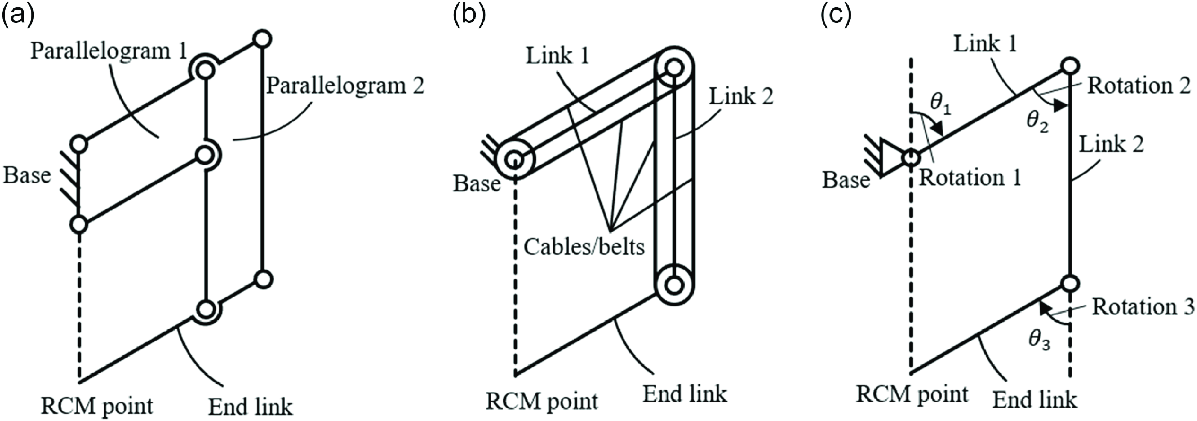
The parallelogram-based mechanism is the most commonly used RCM mechanism in MIS robots, which basically consists of two parallelogram linkages. Due to the constraint of the two parallelogram linkages, the movement of the end link is determined to be a pure rotation around a fixed point (i.e., the incision point or RCM point), which is not a physical part of the mechanism, as illustrated in Figure 1(a). The rigid link structure used in the two parallelogram linkages can be replaced by a cable-pulley (or belt-pulley) structure, as illustrated in Figure 1(b).
The parallelogram-based mechanisms. (a) Rigid link structure. (b) Cable-pulley structure. (c) Simplified model.

When a cable-pulley structure is adopted to replace the rigid link structure, the parallelogram-based RCM mechanism can be further simplified into a serial mechanism consisting of three sequential links (link 1, link 2, and the end link) and three joints, as illustrated in Figure 1(c). The DOFs of the serial mechanism can be reduced from three to one with two closed cable loops. In other words, the rotations of the three joints between the links are coupled. Because the cable-pulley structure takes circular pulleys of equal diameter, there is a linear relationship between the three rotational angles (
 $\theta _{1}=\theta _{2}=\theta _{3}$
). Therefore, the outer boundary of such a planar mechanism always forms a parallelogram. Due to the inherent property of equal opposite side lengths in a parallelogram, the lengths of link 1 and link 2 cannot be changed once the distance between the RCM mechanism and patient is established, limiting the potential to make more compact RCM mechanisms.
2.2. Conceptual design of the compact RCM mechanism
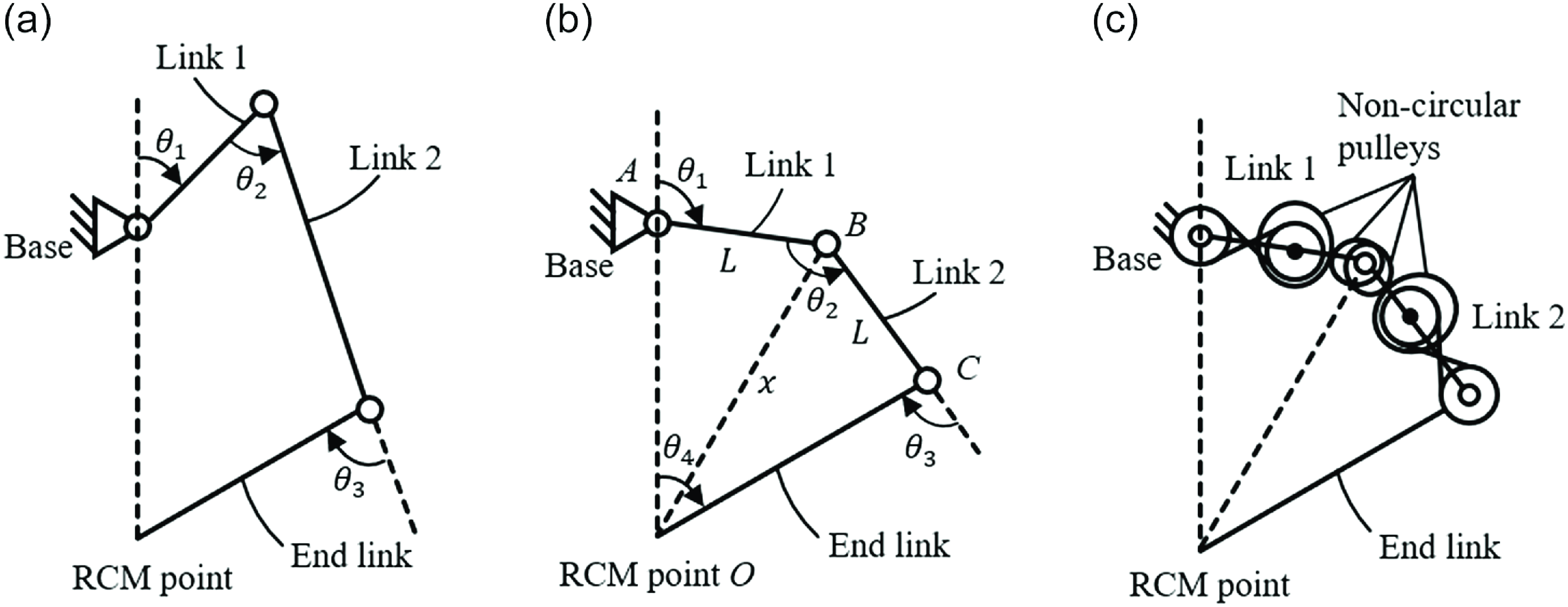
Based on the simplified model for a parallelogram-based mechanism given in Figure 1(c), the lengths of link 1 and link 2 are changed, the distance between the drive point and the RCM point is maintained, and the end link still passes through the original RCM point. Thus, we can get a new mechanism, as shown in Figure 2(a), and the rotational angles of the three joints (
 $\theta _{1}, \theta _{2}, \theta _{3}$
) will no longer exhibit a linear relationship. If this nonlinear relationship can be derived and implemented, this mechanism will also function as an RCM mechanism. As shown in Figure 2(b), some additional constraints are defined to simplify the transmission design: the distance between the drive point and the RCM point is constant with the distance between the surgical instrument mounting point and the RCM point, and the lengths of link 1 and link 2 are equal.
Conceptual design of the proposed RCM mechanism. (a) The initial mechanism. (b) The mechanism with additional constraints. (c) The final RCM mechanism with nonlinear transmission.

With these constraints, the rotational angles
 $\theta _{1}$
and
 $\theta _{3}$
are equal, but their relationship with
 $\theta _{2}$
remains nonlinear. To achieve this nonlinear relationship through mechanical structure, several non-circular pulley joints with variable transmission ratios are designed, as illustrated in Figure 2(c). The basic design principle for the final RCM mechanism is elaborated as follows. First, the nonlinear relationship between the rotational angles of the three joints are established. Second, the nonlinear transmission system with non-circular pulley joints is designed based on the nonlinear relationship. Finally, the RCM function is achieved through closed cable loops in the nonlinear transmission system. Notably, the non-circular pulleys depicted in Figure 2(c) are only schematic representation and do not reflect the actual shape of the non-circular pulleys. A detailed description of the pulley structure will be elaborated in Section 3.
2.3. The nonlinear relationship and range of motion for the compact RCM mechanism
The schematic representation of the RCM mechanism is illustrated in Figure 2(b). Here we use line segments AB, BC, and OC to represent link 1, link 2, and end link mentioned in the conceptual design of the mechanism. According to the given constraints, we have
 $L_{AB}=L_{BC}=L$
and
 $L_{OA}=L_{OC}=R$
. In addition,
 $L_{OB}$
is set as
 $x$
.
Based on the symmetry characteristics of the mechanism, it obtains:
 \begin{equation} \theta _{1}=\theta _{3} \end{equation}
In accordance with the trigonometric cosine theorem, it derives:
 \begin{equation} {\cos}\left(\pi -\theta _{1}\right)=\frac{L^{2}+R^{2}-x^{2}}{2LR} \end{equation}
In accordance with the trigonometric sine theorem, it derives:
 \begin{equation} \frac{x}{{\sin}\left(\pi -\theta_{1}\right)}=\frac{R}{{\sin}\left(\frac{-\theta _{2}}{2}\right)}=\frac{L}{{\sin}\left(\frac{\theta _{4}}{2}\right)} \end{equation}
Integrating Eqs. (1), (2) and (3), we can obtain:
 \begin{equation} \left\{\begin{array}{l}\theta _{2}=-2\,{\arcsin }\left(\frac{R{\sin}\theta _{1}}{\sqrt{L^{2}+R^{2}+2LR{\cos}\theta _{1}}}\right)\\\theta _{3}=\theta _{1}\\\theta _{4}=2\,{\arcsin }\left(\frac{L{\sin}\theta _{1}}{\sqrt{L^{2}+R^{2}+2LR{\cos}\theta _{1}}}\right)\end{array}\right. \end{equation}
This equation elucidates the relationship among
 $\theta _{2}$
,
 $\theta _{3}$
, and
 $\theta _{4}$
with respect to
 $\theta _{1}$
. The relationship between
 $\theta _{1}$
,
 $\theta _{2}$
, and
 $\theta _{3}$
represents the coupling motion between the three joints. In particular, the expression of
 $\theta _{1}$
and
 $\theta _{4}$
reflects the relationship between the input and output of the mechanism, which can be used for motion control. Assume
 $k=L/R$
, and Eq. (4) can be expressed as:
 \begin{align} \begin{cases} \theta _{2}=-2{\arcsin } \left(\dfrac{{\sin}\theta _{1}}{\sqrt{k^{2}+2k{\cos}\theta _{1}+1}}\right)\\ \theta _{3}=\theta _{1}\\ \theta _{4}=2{\arcsin } \left(\dfrac{k{\sin}\theta _{1}}{\sqrt{k^{2}+2k{\cos}\theta _{1}+1}}\right) \end{cases} \\[-10pt] \nonumber\end{align}
where
 $k\in (0,1)$
. Clearly, the coupling relationship between the three joints varies with the value of
 $k$
.
When link 1 and link 2 are collinear, the mechanism will reach the limit position. Consequently, the range of motion (ROM) of this mechanism is contingent upon the value of
 $k$
. According to the cosine rule of triangles, we have:
 \begin{equation} {\cos}\beta =\frac{R^{2}+R^{2}-\left(2kR\right)^{2}}{2R^{2}}\end{equation}
where
 $\beta$
is the angle between link OC and the vertical direction when the link reaches its limit position.
The relationship between the ROM
 $\alpha$
and the value of
 $k$
can be calculated as:
 \begin{equation} \alpha =2\beta =2\mathit{\arccos } \left(1-2k^{2}\right) \end{equation}
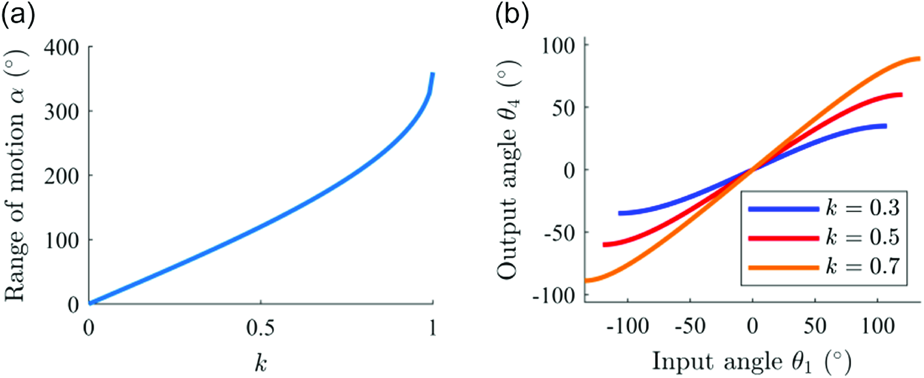
Figure 3(a) illustrates the variation curve of the ROM. Clearly, the ROM shows an increasing trend with the value of
 $k$
. When
 $k$
= 1, the mechanism functions as a parallelogram-based mechanism, with a theoretical ROM of 360
 $^{\circ}$
.
(a) Relationship between the ROM and the value of
 $k$
. (b) Relationship between the input angle and the output angle under different
 $k$
values.

Based on the relationship between the ROM and
 $k$
, we can obtain the relationship between the input angle
 $\theta _{1}$
and the output angle
 $\theta _{4}$
in the ROM under different
 $k$
values, as shown in Figure 3(b). The nonlinear relationship between the input and output angles cannot be realized with conventional cable-pulley (or belt-pulley) joints that can only achieve invariable transmission ratios. This requires the design of novel cable-pulley (or belt-pulley) joints for the nonlinear transmission system.
3. Mechanism design
3.1. Transmission principle of the belt-pulley structure based on traction
Cable-pulley structures and belt-pulley structures have been widely used in the design of RCM mechanisms. Cables and belts are both flexible elements, with similar transmission principles. Compared with cables, steel belts can easily achieve greater tensile strength in the length direction, which means less elastic elongation and error. In addition, our design of the RCM mechanism requires the transmission element to have a smaller thickness. The steel belts can be designed to have a smaller thickness (such as 0.1 mm), while the cables used in surgical instruments generally have a diameter of about 0.5 mm. Therefore, the steel belts are selected for the transmission structure design.
According to the transmission principle, steel belt transmission can be divided into three different forms, including friction-based transmission, meshing transmission, and traction-based transmission. The friction-based belt transmission can result in frictional loss and slip during the operation, and the meshing belt transmission is faced with the transmission error due to the meshing gap. In contrast, the traction-based scheme has a high transmission efficiency, without any slip or transmission gap, making it an ideal choice for the construction of RCM mechanisms in surgical robots. In this scheme, the transfer of force/torque is mainly achieved by the tractive force of the steel belts. The rolling friction between the steel belts and the pulleys is much smaller than the tractive force of the steel belts, allowing a high force/torque transfer efficiency. Moreover, the steel belts, as flexible elements in the transmission structure, possess relatively high tensile stiffness and are pre-tensioned during assembly. Although the use of flexible elements in transmission may lead to vibration issues, increasing the initial tension has been proven to effectively reduce the amplitude of the vibrations [Reference Kawamura, Choe, Tanaka and Pandian25, Reference Schmidt, Kraus and Pott26]. Furthermore, increasing the initial tension also results in low hysteresis under loading, thereby enabling the transmission system to achieve a high dynamic response speed. Below we will take the double-parallelogram mechanism as an example to introduce the traction-based belt-pulley structure and explain its transmission principle.
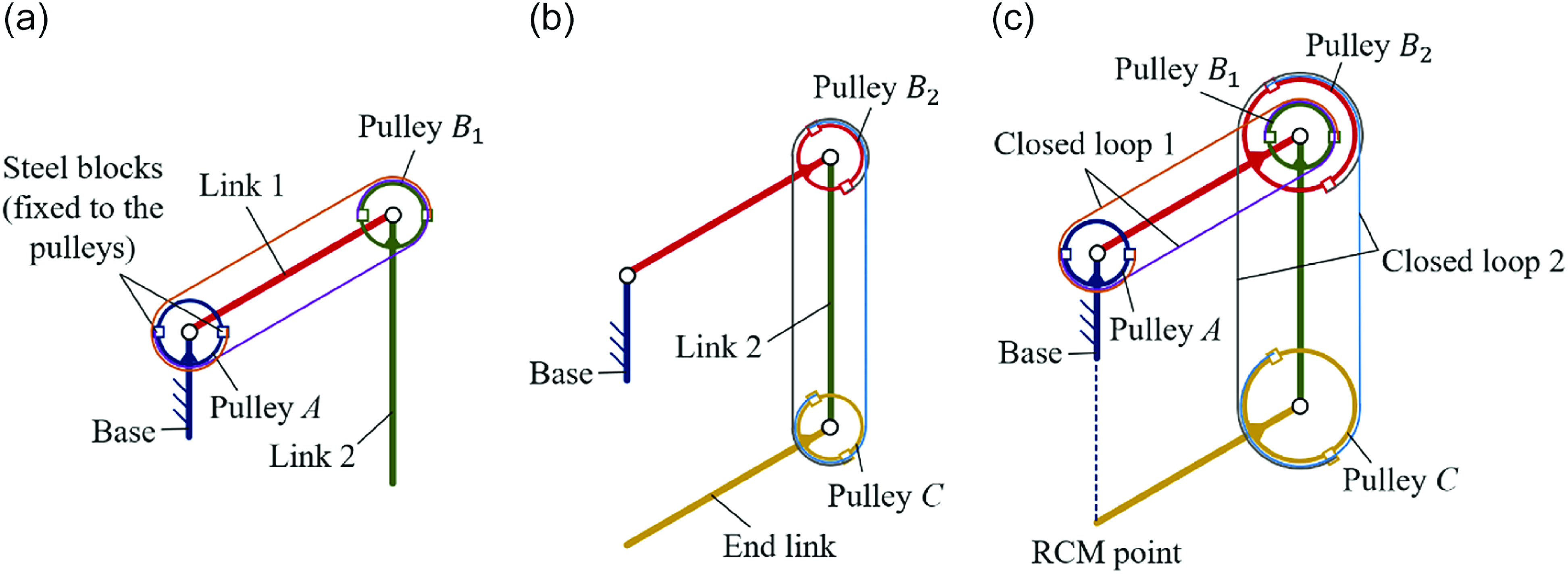
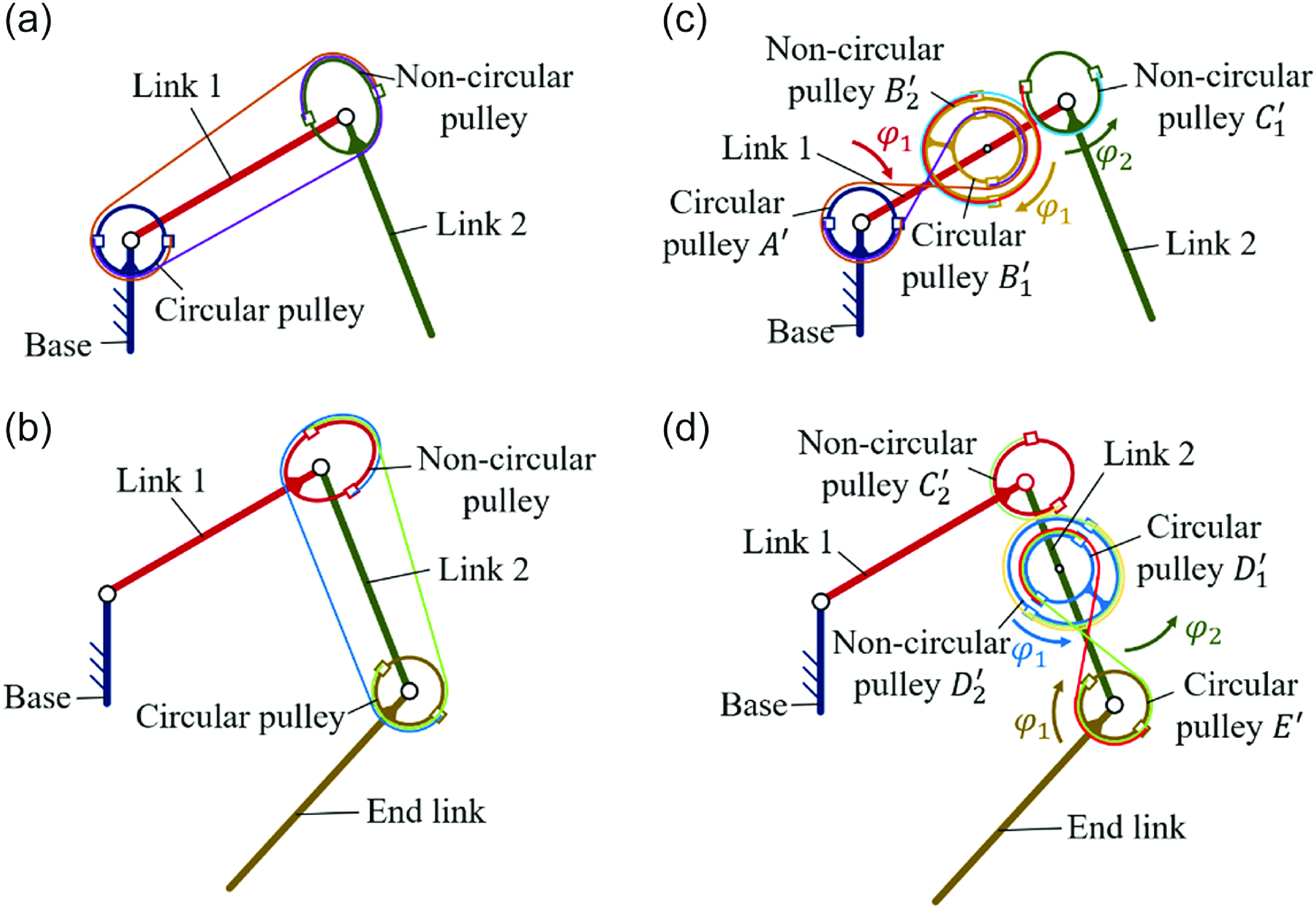
As mentioned previously, a double-parallelogram mechanism requires coupling of three rotational motions through two closed loops. Each closed loop contains two steel belts to transmit motion and power in both directions. The steel belts are fixed on the steel blocks by welding or other ways, and the steel blocks are fixed on the pulleys by threaded connections, as shown in Figure 4(a) and Figure 4(b). Closed loop 1 consists of a base, link 1, and link 2, connected in series by two rotational joints, as well as two equal-diameter circular pulleys
 $A$
and
 $B_{1}$
installed at these joints. Specifically, pulley
 $A$
is fixed to the base, pulley
 $B_{1}$
is fixed to link 2, and link 1 is directly driven by the motor. When link 1 rotates by
 $\theta$
relative to the base, pulley
 $A$
rotates by
 $-\theta$
relative to link 1, and pulley
 $B_{1}$
also rotates by
 $-\theta$
relative to link 1, as pulled by the steel belt. In this case, the rotation of link 2 relative to the base is 0, meaning that link 2 and the base are always parallel. The transmission principle of closed loop 2 is the same as that of closed loop 1, which consists of link 1, link 2, and end link, serially connected by rotational joints, as well as pulleys
 $B_{2}$
and
 $C$
installed at the two rotational joints. Pulley
 $B_{2}$
and link 1 are fixed together, while pulley
 $C$
and the end link are fixed together. Under the action of closed-loop transmission, the end link is always parallel to link 1. The complete double-parallelogram mechanism based on the belt-pulley structure is obtained by integrating closed loop 1 and closed loop 2, as shown in Figure 4(c), where closed loop 2 is enlarged to clearly present the transmission structure.
The belt-pulley structure based on traction in a double-parallelogram mechanism. (a) Closed loop 1. (b) Closed loop 2. (c) The complete transmission structure.

3.2. Nonlinear transmission schemes with non-circular pulleys
As mentioned above, a nonlinear transmission system is required to achieve the coupling relationship between joints. Here, two schemes for the nonlinear transmission are presented, between which the more effective one will be selected.
The first scheme is illustrated in Figure 5(a) and Figure 5(b), corresponding to the two closed loops respectively. In each closed loop, a circular pulley and a non-circular pulley are connected by two steel belts to transmit power in both directions. When the circular pulley rotates by a specified angle relative to the link, the non-circular pulley will rotate by a different angle, which is determined by the profile design of the non-circular pulley. Although this scheme is straightforward, the tangent points between the belts and pulleys will vary during the rotation, which may result in belt slackening.
Layout of the two schemes. (a) The first part and (b) second part of the first scheme. (c) The first part and (d) second part of the second scheme.

The second scheme involves achieving power transmission between two adjacent rotational axes in a defined angular relationship. Non-circular gears may be designed for this scheme [Reference Lozzi27]. Alternatively, a pair of cross linked non-circular pulleys with two cables/belts can also be used to transmit power in both directions [Reference Nai, Herder and Tuijthof28–Reference Suh and Kim30]. In this case, the two non-circular pulleys are adjacent, and they achieve the same motion effect as meshing gears through a cable/belt constraint. Here, the non-circular pulleys are selected due to the complexity associated with manufacturing non-circular gears, as well as the errors introduced by gear gaps in transmission. The transmission structure with non-circular pulleys has seen applications in surgical instruments [Reference Suh and Kim30, Reference Li, Yu, Bai, Cai, Hao and Zhao31], demonstrating its potential for high-reliability manufacturing in surgical robots. The relative rotation of the two adjacent non-circular pulleys is still achieved by the traction-based belt transmission, and the potential errors caused by elastic elongation of the steel belts will be discussed in Section 4.
Specifically, this scheme comprises two transmission parts. As shown in Figure 5(c), the first part includes a base, link 1, link 2, two circular pulleys
 $A'$
and
 $B_{1}^{'}$
, two non-circular pulleys
 $B_{2}^{'}$
and
 $C_{1}^{'}$
, and four steel belts. Among them, the circular pulley
 $A'$
is fixed to the base, the circular pulley
 $B_{1}^{'}$
is coaxially fixed to the non-circular pulley
 $B_{2}^{'}$
, hinged together on link 1, and link 2 is fixed to the non-circular pulley
 $C_{1}^{'}$
. Two adjacent non-circular pulleys
 $B_{2}^{'}$
and
 $C_{1}^{'}$
are connected by two crossing belts to achieve the meshing-like motion of non-circular gears described above. Two circular pulleys
 $A'$
and
 $B_{1}^{'}$
are connected by two belts in an “8” configuration to compensate for the change in transmission direction induced by the meshing-like motion between the two non-circular pulleys. The assembly scheme of the second part is symmetric to that of the first part, as shown in Figure 5(d), which includes link 1, link 2, end link, two circular pulleys
 $D_{1}^{'}$
and
 $E'$
, two non-circular pulleys
 $C_{2}^{'}$
and
 $D_{2}^{'}$
, and four steel belts. Link 1 and link 2 have equal lengths, circular pulleys
 $A'$
,
 $B_{1}^{'}$
,
 $D_{1}^{'}$
, and
 $E'$
have equal diameters, non-circular pulleys
 $B_{2}^{'}$
and
 $D_{2}^{'}$
have the same profile curve, and non-circular pulleys
 $C_{1}^{'}$
and
 $C_{2}^{'}$
have the same profile curve. In each of the two parts, belt slackening is effectively mitigated, as the two non-circular pulleys remain in constant contact and the “8” shaped transmission uses circular pulleys. Therefore, the second scheme is selected for the further design of the compact RCM mechanism.
The following is a detailed description of the motion process of the selected scheme. First, we must clarify the concepts of absolute motion, which is the motion of a rigid body in the world coordinate system, and relative motion, which is the motion of a rigid body relative to a reference rigid body. In the description below, only the input rotational angle of link 1 performs absolute motion, while the remaining angles perform relative motion.
For the first part of the transmission structure, as shown in Figure 5(c), the base is fixed in the world coordinate system and link 1 is directly driven by the motor to rotate around the base. Assume that link 1 rotates by an angle
 $\varphi _{1}$
from its initial position (vertical position). Since pulley
 $A'$
is fixed to the base, it rotates by
 $-\varphi _{1}$
relative to link 1. Under the action of the belts arranged in the shape of “8”, pulley
 $B_{1}^{'}$
rotates by
 $\varphi _{1}$
relative to link 1, and pulley
 $B_{2}^{'}$
fixed coaxially with pulley
 $B_{1}^{'}$
also rotates by
 $\varphi _{1}$
relative to link 1. Since the motion between the non-circular pulleys
 $B_{2}^{'}$
and
 $C_{1}^{'}$
is performed, as previously described, similar to a set of meshing non-circular gears, pulley
 $C_{1}^{'}$
rotates by
 $\varphi _{2}$
relative to link 1, and link 2 fixed to pulley
 $C_{1}^{'}$
also rotates by
 $\varphi _{2}$
relative to link 1. The profile curves of the non-circular pulleys
 $B_{2}^{'}$
and
 $C_{1}^{'}$
determine the relationship between
 $\varphi _{1}$
and
 $\varphi _{2}$
, so the desired motion can be achieved by properly designing these profile curves, which will be elaborated in the next subsection.
The second part of the transmission structure, as shown in Figure 5(d), is symmetrical to the first part. As mentioned above, link 2 rotates by
 $\varphi _{2}$
relative to link 1, as well as pulley
 $C_{2}^{'}$
fixed to link 1. In other words, pulley
 $C_{2}^{'}$
rotates by
 $-\varphi _{2}$
relative to link 2. Under the constraint of the steel belts crossing between the non-circular pulleys
 $C_{2}^{'}$
and
 $D_{2}^{'}$
, pulley
 $D_{2}^{'}$
rotates by
 $-\varphi _{1}$
relative to link 2. Since the non-circular pulley
 $D_{2}^{'}$
and the circular pulley
 $D_{1}^{'}$
are coaxially fixed, pulley
 $D_{1}^{'}$
also rotates by
 $-\varphi _{1}$
relative to link 2. Under the constraint of the “8” shaped steel belts between pulleys
 $D_{1}^{'}$
and
 $E'$
, pulley
 $E'$
rotates by
 $\varphi _{1}$
relative to link 2, and the end link fixed to pulley
 $E'$
also rotates by
 $\varphi _{1}$
relative to link 2.
3.3. Design of the non-circular pulleys
As mentioned above, we need to design the profile curves of the non-circular pulleys to ensure that the proposed transmission scheme allows the end link to always pass through the RCM point. It is sufficient to determine the profile curves of non-circular pulleys in one part of the transmission structure, since non-circular pulleys
 $B_{2}^{'}$
and
 $D_{2}^{'}$
have the same profile curve, and non-circular pulleys
 $C_{1}^{'}$
and
 $C_{2}^{'}$
have the same profile curve.
As clarified previously, both
 $\varphi _{1}$
and
 $\varphi _{2}$
have two different meanings. In the first meaning,
 $\varphi _{1}$
represents the rotational angle of link 1 relative to the base, and
 $\varphi _{2}$
represents the rotational angle of link 2 relative to link 1. These are consistent with the definition of
 $\theta _{1}$
and
 $\theta _{2}$
in Section 2.3, and therefore they should satisfy the kinematic relationship expressed by Eq. (5). Substituting
 $\theta _{1}=\varphi _{1}$
and
 $\theta _{2}=\varphi _{2}$
into Eq. (5) gives:
 \begin{equation} \varphi _{2}=-2{\arcsin } \left(\frac{{\sin}\varphi _{1}}{\sqrt{k^{2}+2k{\cos}\varphi _{1}+1}}\right) \end{equation}
In the second meaning,
 $\varphi _{1}$
and
 $\varphi _{2}$
represent the rotational angles of non-circular pulleys
 $B_{2}^{'}$
and
 $C_{1}^{'}$
relative to link 1. Therefore, the rotational angle
 $\varphi _{1}$
of non-circular pulley
 $B_{2}^{'}$
relative to link 1 and the rotational angle
 $\varphi _{2}$
of non-circular pulley
 $C_{1}^{'}$
relative to link 1 should also satisfy the relationship expressed by Eq. (8). The rotation of non-circular pulleys
 $B_{2}^{'}$
and
 $C_{1}^{'}$
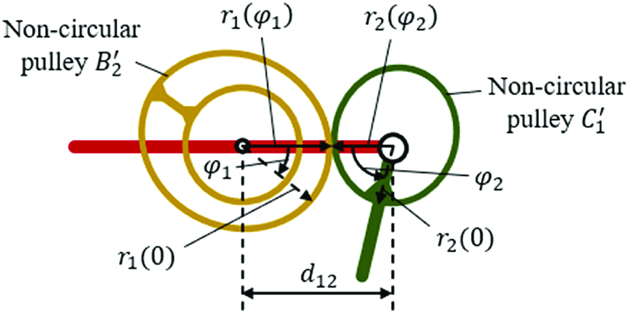
relative to link 1 is illustrated in Figure 6. The radius of the non-circular pulley
 $B_{2}^{'}$
is denoted as
 $r_{1}(\varphi _{1})$
, while the radius of the non-circular pulley
 $C_{1}^{'}$
is denoted as
 $r_{2}(\varphi _{2})$
. The center distance between pulleys
 $B_{2}^{'}$
and
 $C_{1}^{'}$
is given as
 $d_{12}$
.
Schematics of the non-circular pulleys
 $B_{2}^{'}$
and
 $C_{1}^{'}$
rotating relative to link 1.

As mentioned previously, the thickness of the steel belts in the selected transmission scheme is negligible compared to the pulley radius. If this thickness is ignored, the relationship between the center distance
 $d_{12}$
and the radii of the two pulleys is given as:
 \begin{equation} r_{1}\left(\varphi _{1}\right)+r_{2}\left(\varphi _{2}\right)=d_{12} \end{equation}
Since the two non-circular pulleys rotate in connect with each other, their rotational angles and radii have the following relationship:
 \begin{equation} \int r_{1}\left(\varphi _{1}\right)\textrm{d}\varphi _{1}=-\int r_{2}\left(\varphi _{2}\right)\textrm{d}\varphi _{2} \end{equation}
By combining Eqs. (8), (9), and (10), the radii of both non-circular pulleys can be expressed as:
 \begin{align}&\qquad\qquad\qquad\qquad r_{1}\left(\varphi _{1}\right)=\frac{2d_{12}\left(k{\cos}\varphi _{1}+1\right)}{k^{2}+4k{\cos}\varphi _{1}+3}\nonumber\\[-10pt] \end{align}
 \begin{align}& r_{2}\left(\varphi _{2}\right)=\frac{d_{12}\left(k^{2}-k\left(2k{\sin}^{2}\dfrac{\varphi _{2}}{2}-\sqrt{-k^{2}{\sin}^{2}\varphi _{2}+2{\cos}\varphi _{2}+2}\right)+1\right)}{k^{2}-2k\left(2k{\sin}^{2}\dfrac{\varphi _{2}}{2}-\sqrt{-k^{2}{\sin}^{2}\varphi _{2}+2{\cos}\varphi _{2}+2}\right)+3}\end{align}
Although the thickness of the steel belts is very small, its effect on the transmission still needs to be considered in practice. In a set of non-circular pulleys designed according to Eqs. (11) and (12), the steel belts will be compressed by the two pulleys rotating in contact, which will affect the smoothness of the transmission. Therefore, the radii of the non-circular pulleys
 $B_{2}^{'}$
and
 $C_{1}^{'}$
are corrected as
 $r_{1}^{'}(\varphi _{1})=r_{1}(\varphi _{1})-t/2$
and
 $r_{2}^{'}(\varphi _{2})=r_{2}(\varphi _{2})-t/2$
, respectively, where
 $t$
is the thickness of the steel belts. This adjustment avoids the issue of transmission instability without altering the transmission relationship.
The center distance
 $d_{12}$
is set at 40 mm to obtain the profile curves of the non-circular pulleys
 $B_{2}^{'}$
(
 $D_{2}^{'}$
) and
 $C_{1}^{'}$
(
 $C_{2}^{'}$
) with the
 $k$
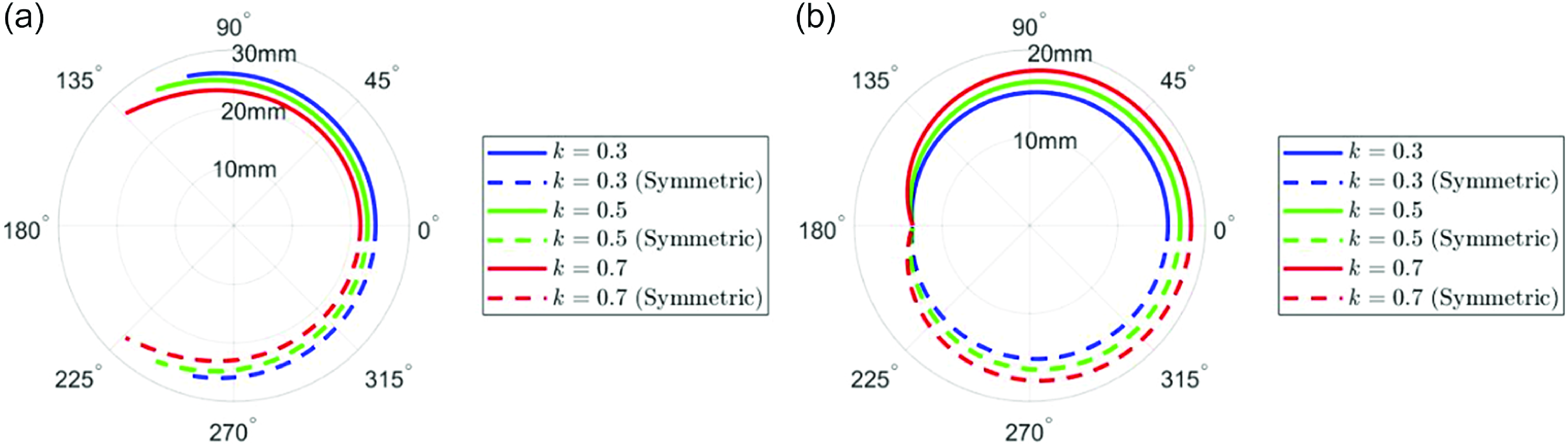
value of 0.3, 0.5, and 0.7, respectively. Since the RCM mechanism shows symmetrical rotation from the initial position to the two directions, the profile curves of these non-circular pulleys are also axisymmetric, as illustrated in Figure 7(a) and Figure 7(b).
(a) Profile curves of the non-circular pulleys
 $B_{2}^{'}$
and
 $D_{2}^{'}$
under different k values. (b) Profile curves of the non-circular pulleys
 $C_{1}^{'}$
and
 $C_{2}^{'}$
under different k values.

3.4. Prototype design and fabrication
Based on prior experience in designing a robotic system, the distance between the drive point and the RCM point is set to 180 mm. After this parameter is determined, the length of link 1 and 2 depends only on the required workspace (according to Eq. (7), the value of
 $k$
determines the ROM, where
 $k$
represents the ratio of the link length to the distance between the drive point and the RCM point).
According to Rosen et al. [Reference Rosen, Brown, Chang, Barreca, Sinanan and Hannaford32, Reference Rosen, Brown, Chang, Sinanan and Hannaford33], approximately 95% of the operative duration in MIS procedures is characterized by the movements of the surgical instruments concentrated within a conical space, with the entry point as the apex and an angle of 60
 $^{\circ}$
at the apex. To ensure that surgical instruments can access any area within the abdominal cavity intact, the RCM mechanism must have a ROM of at least 90
 $^{\circ}$
. In addition, fixing belts on the pulley will occupy a certain length of the profile curve, making the actual ROM smaller than the theoretical value. Taking all these into consideration, a value of
 $k$
= 0.5 is selected to provide the RCM mechanism with a theoretical ROM of 120
 $^{\circ}$
. This value meets the 90
 $^{\circ}$
ROM required for most abdominal MIS applications while also ensuring the miniaturization and compactness of the mechanism. For MIS applications that may require a larger workspace, the proposed RCM mechanism can further achieve a larger ROM by increasing the design parameter
 $k$
. Conversely, for MIS applications that require only a 60° ROM, the proposed RCM mechanism can achieve a shorter link length and enhanced compactness by reducing the design parameter
 $k$
.
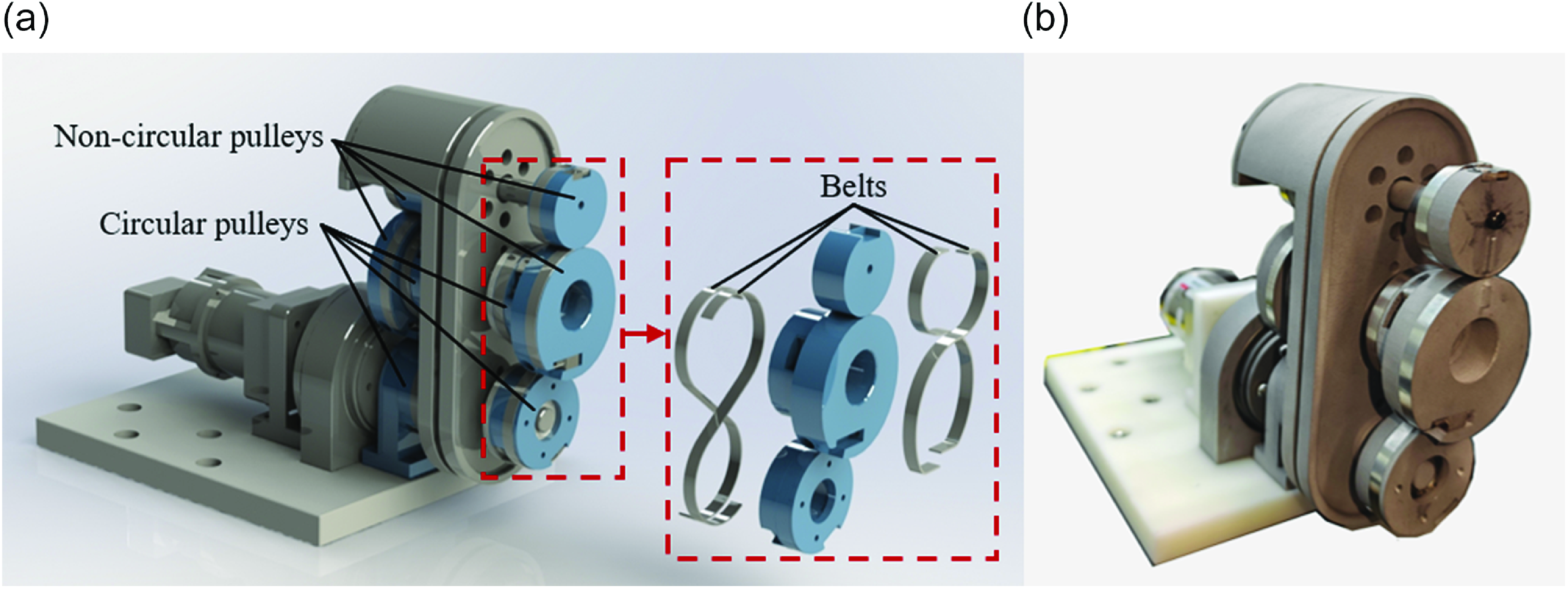
With these parameters, a virtual prototype and a physical prototype are built, as depicted in Figure 8(a) and Figure 8(b).
(a) The virtual prototype and (b) physical prototype of the compact RCM mechanism.

4. Error analysis
The proposed mechanism uses multiple closed-loop steel belts for transmission. As flexible elements similar to cables, the steel belts undergo elastic deformation when subjected to the traction force, which affects the stiffness of the mechanism and, consequently, its motion accuracy. The errors caused by the elasticity of such transmission elements are generally analyzed with error models [Reference Huang, Yin, Liu and Yang34, Reference Zhang, Li, Kong and Wang35]. In this section, we develop an error model to analyze the transmission errors caused by the elasticity of the steel belts under load. A force analysis of the mechanism is performed to obtain the joint torques, based on which changes in the steel belt tensions are determined to calculate changes in steel belt lengths. Finally, the joint angle errors are calculated based on the changes in steel belt lengths and then mapped to the tip position errors of the mechanism.
4.1. Static analysis of the mechanism
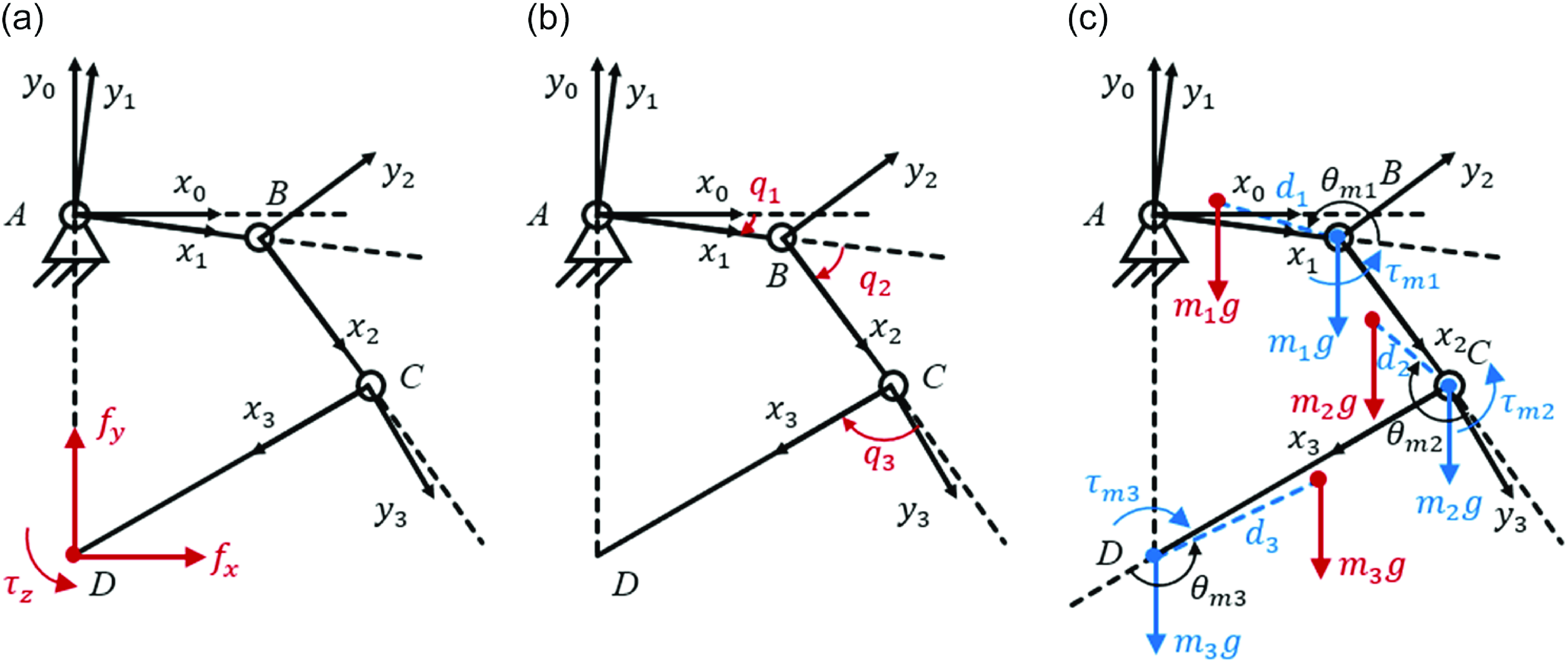
To simplify the modeling process, the force analysis neglects the motion inertia of the mechanism and joint friction. The loads acting on the RCM mechanism mainly include the external loads on the end link and the gravity of the links themselves. Since the proposed mechanism is a planar mechanism, it is assumed that both external loads and gravity act within its plane. These two components are separately mapped to the joint torques, which are then summed to obtain the total torque acting on each joint.
According to the principle of force translation, the external loads acting on the end link can be converted into forces and torques acting at its tip, as shown in Figure 9(a). Therefore, the total external load on the end link can be represented by the tip external load
 $\boldsymbol{F}_e$
, which can be expressed as:
 \begin{equation} \boldsymbol{F}_{e}=\left(\begin{array}{c} \boldsymbol{f}_{e}\\ \boldsymbol\tau _{e} \end{array}\right)=\left(\begin{array}{c} {\boldsymbol{f}}_{x}\\ \begin{array}{c} {\boldsymbol{f}}_{y}\\ \tau _{z} \end{array} \end{array}\right) \end{equation}
where
 $f_{x}$
and
 $f_{y}$
represent the horizontal and vertical components of the external force, respectively, and
 $\tau _{z}$
represents the torque.
(a) Analysis of the external load. (b) The kinematic model. (c) Mapping the link gravitational forces to the tip loads.

According to the principle of virtual work, the tip external load of the mechanism can be mapped to the joint torques using the Jacobian matrix. Ignoring the constraints of the belt-pulley structure, the kinematic model of the proposed mechanism is established using the Denavit–Hartenberg method, as shown in Figure 9(b). The relationship between the position and orientation of the end link and the joint angles is:
 \begin{equation} \left(\begin{array}{c} x_{D}\\ \begin{array}{c} y_{D}\\ \varphi _{CD} \end{array} \end{array}\right)=\left(\begin{array}{c} l_{1}c_{1}+l_{2}c_{12}+l_{3}c_{123}\\ \begin{array}{c} l_{1}s_{1}+l_{2}s_{12}+l_{3}s_{123}\\ q_{1}+q_{2}+q_{3} \end{array} \end{array}\right) \end{equation}
where
 $x_{D}$
and
 $y_{D}$
represent the position of the mechanism tip
 $D ;\;\varphi _{CD}$
represents the orientation of the end link
 $CD ;\; l_{1}$
,
 $l_{2}$
, and
 $l_{3}$
represent the lengths of links
 $AB$
,
 $BC$
, and
 $CD$
, respectively;
 $q_{1}$
,
 $q_{2}$
, and
 $q_{3}$
represent the relative rotational angles of each link’s coordinate system with respect to the previous one;
 $c_{1}$
,
 $c_{12}$
, and
 $c_{123}$
represent
 ${\cos}q_{1}$
,
 ${\cos}(q_{1}+q_{2})$
, and
 ${\cos}(q_{1}+q_{2}+q_{3})$
, respectively;
 $s_{1}$
,
 $s_{12}$
,
 $s_{123}$
represent
 ${\sin}q_{1}$
,
 ${\sin}(q_{1}+q_{2})$
, and
 ${\sin}(q_{1}+q_{2}+q_{3})$
, respectively.
In particular,
 $q_{1}$
,
 $q_{2}$
,
 $q_{3}$
and
 $\theta _{1}$
,
 $\theta _{2}$
,
 $\theta _{3}$
mentioned in Section 2.3 have the following relationship:
 \begin{equation} \begin{cases} q_{1}=\theta _{1}+\dfrac{\pi }{2}\\ q_{2}=\theta _{2}-\pi \\ q_{3}=\theta _{3} \end{cases} \end{equation}
Differentiating Eq. (14) yields:
 \begin{equation} \left(\begin{array}{c} \dot{x}_{D}\\ \begin{array}{c} \dot{y}_{D}\\ \dot{\varphi }_{CD} \end{array} \end{array}\right)=\left(\begin{array}{ccc} -l_{1}s_{1}-l_{2}s_{12}-l_{3}s_{123} & -l_{2}s_{12}-l_{3}s_{123} & -l_{3}s_{123}\\ l_{1}c_{1}+l_{2}c_{12}+l_{3}c_{123} & l_{2}c_{12}+l_{3}c_{123} & l_{3}c_{123}\\ 1 & 1 & 1 \end{array}\right)\times \left(\begin{array}{c} \dot{q}_{1}\\ \begin{array}{c} \dot{q}_{2}\\ \dot{q}_{3} \end{array} \end{array}\right)=\boldsymbol{J}\dot{\boldsymbol{q}} \end{equation}
where
 $J$
is the Jacobian matrix of the mechanism.
According to the principle of virtual work, the relationship between the tip external load
 $\boldsymbol{F}_{e}$
and the resulting joint torques (denoted by
 $\boldsymbol\tau _{F}$
) is as follows:
 \begin{equation} \boldsymbol\tau _{F}=\boldsymbol{J}^{T}\boldsymbol{F}_{e} \end{equation}
The gravity of the links can also be mapped to the joint torques. First, the gravity of each link is converted into the corresponding tip load, as shown in Figure 9(c). Then, each tip load is transformed into the torques acting on the corresponding joints of the mechanism.
For links
 $AB$
,
 $BC$
, and
 $CD$
, let their gravitational forces be
 $m_{1}g$
,
 $m_{2}g$
, and
 $m_{3}g$
, respectively. These forces are converted into the corresponding tip loads acting at points
 $B$
,
 $C$
, and
 $D$
, respectively, expressed as:
 \begin{equation} \boldsymbol{F}_{mi}=\left(\begin{array}{c} \boldsymbol{f}_{mi}\\ \boldsymbol\tau _{mi} \end{array}\right)=\left(\begin{array}{c} 0\\ \begin{array}{c} -m_{i}g\\[5pt] -m_{i}gd_{i}{\cos}\left(\sum _{i=1}^{i}q_{i}+\theta _{mi}\right) \end{array} \end{array}\right),i=1,2,3 \end{equation}
where
 $d_{i}$
(
 $i=1,2,3$
) represents the distance between the center of mass and the tip of each link, and
 $\theta _{mi}$
(
 $i=1,2,3$
) represents the angle between the link and the line connecting its center of mass to its tip.
The tip load
 $\boldsymbol{F}_{m3}$
, corresponding to the gravity of link
 $CD$
, acts on tip
 $D$
and is mapped to the torques of joints
 $A$
,
 $B$
, and
 $C$
. The tip load
 $\boldsymbol{F}_{m2}$
, corresponding to the gravity of link
 $BC$
, acts on tip
 $C$
. Neglecting link
 $CD$
,
 $F_{m2}$
is mapped to the torques of joints
 $A$
and
 $B$
. The tip load
 $\boldsymbol{F}_{m1}$
, corresponding to the gravity of link
 $AB$
, acts on tip
 $B$
. Neglecting links
 $BC$
and
 $CD$
,
 $\boldsymbol{F}_{m1}$
is mapped to the torque of joint
 $A$
. By summing these three parts, the joint torques caused by the gravity of the links can be obtained as:
 \begin{equation} \boldsymbol\tau _{M}=\boldsymbol{J}^{T}\boldsymbol{F}_{m3}+\left(\begin{array}{c} \boldsymbol{J}_{AC}^{T}\boldsymbol{F}_{m2}\\ 0 \end{array}\right)+\left(\begin{array}{c} \boldsymbol{J}_{AB}^{T}\boldsymbol{F}_{m1}\\ \begin{array}{c} 0\\ 0 \end{array} \end{array}\right) \end{equation}
where
 $\boldsymbol{J}_{AC}$
denotes the Jacobian matrix of the mechanism when link
 $CD$
is ignored, and
 $\boldsymbol{J}_{AB}$
denotes the Jacobian matrix of the mechanism when links
 $BC$
and
 $CD$
are ignored.
The total joint torque vector
 $\boldsymbol\tau$
can be obtained by summing the joint torque vectors
 $\boldsymbol\tau _{F}$
and
 $\boldsymbol\tau _{M}$
corresponding to the tip external load and the gravity of each link obtained above, expressed as:
 \begin{equation} \boldsymbol\tau =\left(\begin{array}{c} \tau _{1}\\ \begin{array}{c} \tau _{2}\\ \tau _{3} \end{array} \end{array}\right)=\boldsymbol\tau _{F}+\boldsymbol\tau _{M} \end{equation}
where
 $\tau _{1}$
,
 $\tau _{2}$
, and
 $\tau _{3}$
represent the torques at joints
 $A$
,
 $B$
, and
 $C$
, respectively.
4.2. Belt tension analysis
In the proposed mechanism, both circular and non-circular pulleys are driven by steel belts. When torques are applied, the tension in the steel belts changes by the principle of force equilibrium.
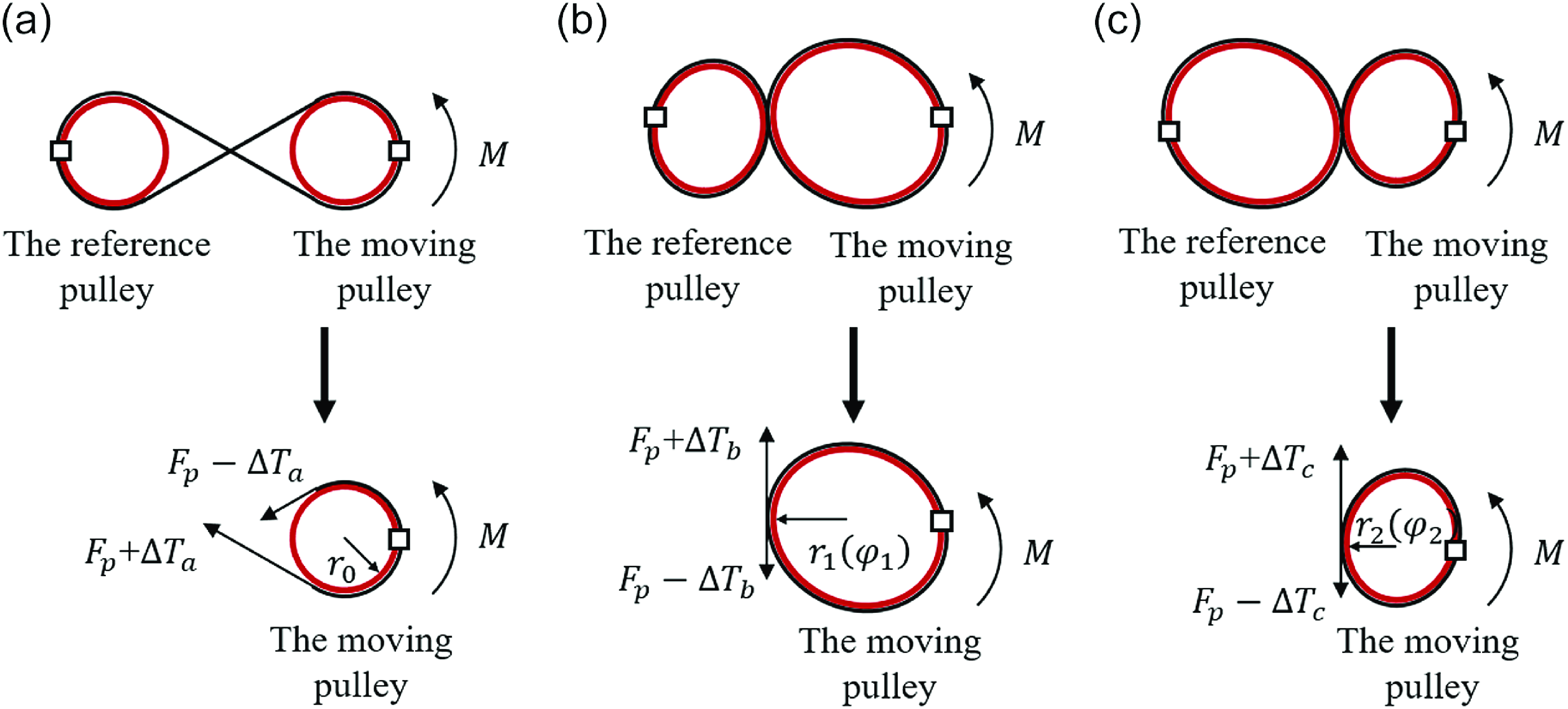
Figure 10(a) shows the force analysis of a circular pulley, while Figure 10(b) and Figure 10(c) illustrate the force analyses of two types of non-circular pulleys. It is assumed that the initial tension in all steel belts is
 $F_{p}$
. When torque is applied, one of the two steel belts connected to each pulley becomes tightened, while the other becomes slack. Suppose the tensions in the tightened belts of the three cases become
 $F_{p}+{\unicode[Arial]{x0394}} T_{a}$
,
 $F_{p}+{\unicode[Arial]{x0394}} T_{b}$
, and
 $F_{p}+{\unicode[Arial]{x0394}} T_{c}$
, while the tensions in the slackened belts become
 $F_{p}-{\unicode[Arial]{x0394}} T_{a}$
,
 $F_{p}-{\unicode[Arial]{x0394}} T_{b}$
, and
 $F_{p}-{\unicode[Arial]{x0394}} T_{c}$
, respectively. Through force analysis, we can obtain:
 \begin{equation} \begin{cases} {\unicode[Arial]{x0394}} T_{a}=\dfrac{M}{2r_{0}}\\[8pt] {\unicode[Arial]{x0394}} T_{b}=\dfrac{M}{2r_{1}\left(\varphi _{1}\right)}\\[8pt] {\unicode[Arial]{x0394}} T_{c}=\dfrac{M}{2r_{2}\left(\varphi _{2}\right)} \end{cases} \end{equation}
where
 $r_{0}$
represents the radius of the circular pulley, and
 $r_{1}(\varphi _{1})$
and
 $r_{2}(\varphi _{2})$
, as previously defined in Eqs. (11) and (12), represent the radii of the two types of non-circular pulleys at the points where tension is applied.
Force analysis of the pulleys. (a) The circular pulley. (b) The first type of non-circular pulley (pulleys
 $B_{2}^{'}$
and
 $D_{2}^{'}$
). (c) The second type of non-circular pulley (pulleys
 $C_{1}^{'}$
and
 $C_{2}^{'}$
).

The tension variation of the steel belts under the joint torque
 $\boldsymbol\tau$
in the proposed mechanism is analyzed below. The joint torque
 $\tau _{1}$
is directly balanced by the motor, while
 $\tau _{2}$
and
 $\tau _{3}$
act on the non-circular pulley
 $C_{1}^{'}$
and the circular pulley
 $E'$
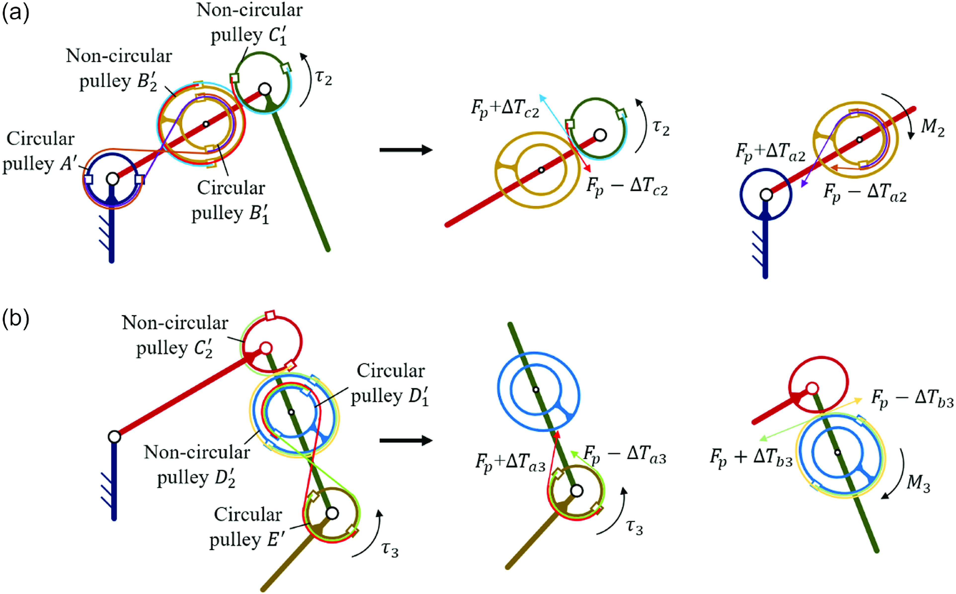
, as shown in Figure 11(a) and Figure 11(b), respectively.
Belt tension variations in the mechanism. (a) The first transmission part. (b) The second transmission part.

As shown in Figure 11(a), when torque
 $\tau _{2}$
is applied to pulley
 $C_{1}^{'}$
, the tensions in the two connected steel belts change to
 $F_{p}+{\unicode[Arial]{x0394}} T_{c2}$
and
 $F_{p}-{\unicode[Arial]{x0394}} T_{c2}$
, respectively. According to Eq. (21),
 ${\unicode[Arial]{x0394}} T_{c2}=\tau _{2}/2r_{2}(\varphi _{2})$
can be obtained. The tensions in these two steel belts act on pulley
 $B_{2}^{'}$
simultaneously, generating a torque
 $M_{2}=-\tau _{2}r_{1}(\varphi _{1})/r_{2}(\varphi _{2})$
. Since pulleys
 $B_{1}^{'}$
and
 $B_{2}^{'}$
are coaxially fixed together, the torque
 $M_{2}$
is also applied to pulley
 $B_{1}^{'}$
. The tensions in the two connected steel belts of the pulley
 $B_{1}^{'}$
change to
 $F_{p}+{\unicode[Arial]{x0394}} T_{a2}$
and
 $F_{p}-{\unicode[Arial]{x0394}} T_{a2}$
, respectively. According to Eq. (21),
 ${\unicode[Arial]{x0394}} T_{a2}=M_{2}/2r_{0}$
can be obtained.
As shown in Figure 11(b), when torque
 $\tau _{3}$
is applied to pulley
 $E'$
, the tensions in the two connected steel belts change to
 $F_{p}+{\unicode[Arial]{x0394}} T_{a3}$
and
 $F_{p}-{\unicode[Arial]{x0394}} T_{a3}$
, respectively. According to Eq. (21),
 ${\unicode[Arial]{x0394}} T_{a3}=\tau _{3}/2r_{0}$
can be obtained. The tensions in these two steel belts act on pulley
 $D_{1}^{'}$
simultaneously, generating a torque
 $M_{3}=-\tau _{3}$
. Since pulleys
 $D_{1}^{'}$
and
 $D_{2}^{'}$
are coaxially fixed together, the torque
 $M_{3}$
is also applied to pulley
 $D_{2}^{'}$
. The tensions in the two connected steel belts of the pulley
 $D_{2}^{'}$
change to
 $F_{p}+{\unicode[Arial]{x0394}} T_{b3}$
and
 $F_{p}-{\unicode[Arial]{x0394}} T_{b3}$
, respectively. According to Eq. (21),
 ${\unicode[Arial]{x0394}} T_{b3}=M_{3}/2r_{1}(\varphi _{1})$
can be obtained.
4.3. Joint angle errors and tip error modeling
Assuming that the elastic elongation of the steel belt is linear, the elongation of the belt is related to its tension, expressed as:
 \begin{equation} \begin{cases} l_{p}-l_{i}=\dfrac{F_{p}l_{i}}{E_{s}A_{s}}\\[8pt] l_{m}-l_{i}=\dfrac{\left(F_{p}+{\unicode[Arial]{x0394}} T\right)l_{i}}{E_{s}A_{s}} \end{cases} \end{equation}
where
 $l_{i}$
denotes the natural length of the steel belt without tension,
 $l_{p}$
denotes the length under the initial tension
 $F_{p}$
,
 $l_{m}$
denotes the length under the combined effect of the initial tension
 $F_{p}$
and the additional tension
 ${\unicode[Arial]{x0394}} T$
, and
 $E_{s}$
and
 $A_{s}$
denote Young’s modulus and the equivalent cross-sectional area of the steel belt, respectively.
By subtracting the two equations of Eq. (22), the elongation of the steel belt under the additional tension
 ${\unicode[Arial]{x0394}} T$
relative to the initial preload state can be obtained, expressed as:
 \begin{equation} {\unicode[Arial]{x0394}} l=l_{m}-l_{p}=\frac{{\unicode[Arial]{x0394}} Tl_{i}}{E_{s}A_{s}}\end{equation}
The relationship between
 ${\unicode[Arial]{x0394}} l$
and the angle error
 ${\unicode[Arial]{x0394}} \theta$
of the pulley is as follows:
 \begin{equation} {\unicode[Arial]{x0394}} \theta =\frac{{\unicode[Arial]{x0394}} l}{r} \end{equation}
where
 $r$
refers to
 $r_{0}$
,
 $r_{1}(\varphi _{1})$
, and
 $r_{2}(\varphi _{2})$
in the three cases.
Combine Eqs. (21), (23), and (24), and substitute the expressions for
 ${\unicode[Arial]{x0394}} T_{a2}$
,
 ${\unicode[Arial]{x0394}} T_{c2}$
,
 ${\unicode[Arial]{x0394}} T_{b3}$
,
 ${\unicode[Arial]{x0394}} T_{a3}$
. Then the angle errors
 ${\unicode[Arial]{x0394}} \theta _{b}$
,
 ${\unicode[Arial]{x0394}} \theta _{c}$
,
 ${\unicode[Arial]{x0394}} \theta _{d}$
, and
 ${\unicode[Arial]{x0394}} \theta _{e}$
of pulleys
 $B_{2}^{'}$
,
 $C_{1}^{'}$
,
 $D_{2}^{'}$
, and
 $E'$
can be obtained as:
 \begin{equation} \begin{cases} {\unicode[Arial]{x0394}} \theta _{b}=\dfrac{-\tau _{2}l_{i2}r_{1}\left(\varphi _{1}\right)}{2E_{s}A_{s}r_{0}^{2}r_{2}\left(\varphi _{2}\right)}\\[8pt] {\unicode[Arial]{x0394}} \theta _{c}=\dfrac{\tau _{2}l_{i1}}{2E_{s}A_{s}r_{2}^{2}\left(\varphi _{2}\right)}\\[8pt] {\unicode[Arial]{x0394}} \theta _{d}=\dfrac{-\tau _{3}l_{i1}}{2E_{s}A_{s}r_{1}^{2}\left(\varphi _{1}\right)}\\[8pt] {\unicode[Arial]{x0394}} \theta _{e}=\dfrac{\tau _{3}l_{i2}}{2E_{s}A_{s}r_{0}^{2}} \end{cases} \end{equation}
where
 $l_{i1}$
and
 $l_{i2}$
represent the initial lengths of the steel belts connecting the two non-circular pulleys and the two circular pulleys, respectively.
The torque
 $\tau _{1}$
is balanced by the motor torque, so the joint angle error
 ${\unicode[Arial]{x0394}} q_{1}$
is 0. The joint angle error
 ${\unicode[Arial]{x0394}} q_{2}$
is accumulated from the angle errors of pulleys
 $B_{2}^{'}$
and
 $C_{1}^{'}$
. The joint angle error
 ${\unicode[Arial]{x0394}} q_{3}$
is accumulated from
 ${\unicode[Arial]{x0394}} q_{2}$
and the angle errors of pulleys
 $D_{2}^{'}$
and
 $E'$
. They are expressed as:
 \begin{equation} \begin{cases} {\unicode[Arial]{x0394}} q_{1}=0\\ {\unicode[Arial]{x0394}} q_{2}=\dfrac{-r_{1}\left(\varphi _{1}\right)}{r_{2}\left(\varphi _{2}\right)}{\unicode[Arial]{x0394}} \theta _{b}+{\unicode[Arial]{x0394}} \theta _{c}\\[8pt] {\unicode[Arial]{x0394}} q_{3}=\dfrac{-r_{2}\left(\varphi _{2}\right)}{r_{1}\left(\varphi _{1}\right)}{\unicode[Arial]{x0394}} q_{2}-{\unicode[Arial]{x0394}} \theta _{d}+{\unicode[Arial]{x0394}} \theta _{e} \end{cases} \end{equation}
By substituting the joint angle errors
 ${\unicode[Arial]{x0394}} q_{1}$
,
 ${\unicode[Arial]{x0394}} q_{2}$
, and
 ${\unicode[Arial]{x0394}} q_{3}$
into Eq. (16), the tip error
 ${\unicode[Arial]{x0394}} \boldsymbol{p}_{D}$
can be obtained, expressed as:
 \begin{equation} {\unicode[Arial]{x0394}} \boldsymbol{p}_{D}=\boldsymbol{J}{\unicode[Arial]{x0394}} \boldsymbol{q}=\boldsymbol{J}\left(\begin{array}{c} {\unicode[Arial]{x0394}} q_{1}\\ {\unicode[Arial]{x0394}} q_{2}\\ {\unicode[Arial]{x0394}} q_{3} \end{array}\right) \end{equation}
Equation (25) reveals that the joint angle errors are primarily affected by three factors: the magnitude of the joint torques, the elasticity of the steel belts, and the radii of the pulleys. These findings provide valuable guidance for selecting pulley design parameters, indicating that employing pulleys with larger radii can enhance the stiffness of the mechanism. Furthermore, the proposed error model offers a theoretical basis for improving the motion accuracy of the mechanism through compensation strategies in future control implementations. Potential approaches include feedforward correction based on model-predicted errors, gain scheduling under varying operational conditions, and adaptive control methods that adjust motion commands in real time. In addition, data-driven methods such as neural network-based compensation may also be integrated with the proposed model to address complex, nonlinear errors.
5. Footprint comparison
The footprint of the proposed mechanism is compared with that of a regular parallelogram-based mechanism. Three key indicators are used to quantify and compare the footprint, including (1) the area enclosed by the mechanism, (2) the space behind the input joint permitting link rotation, and (3) the cumulative length of each link [Reference Liu, Chen, Caro, Briot, Harewood and Chen23]. For ease of quantitative analysis, both RCM mechanisms are simplified by disregarding width of the links.
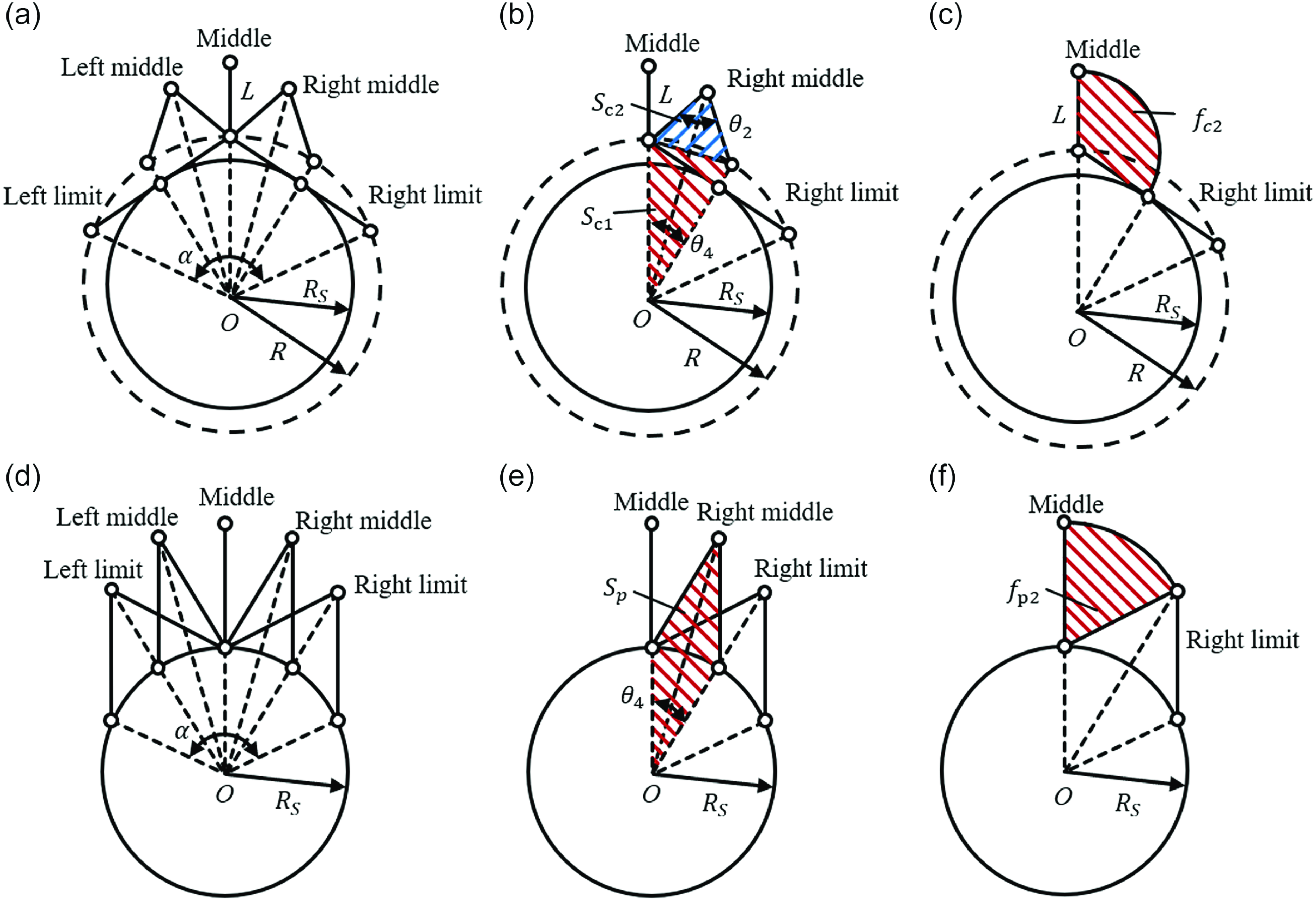
Figures 12(a) and 12(d) illustrates five key positions of the two mechanisms throughout the rotational process: the left limit, left middle, middle, right middle, and right limit. Here, we define the absolute safe distance between the RCM mechanism and the patient’s body as
 $R_{S}$
. In this context, there is a circular safe zone surrounding the incision where no links other than the end link can enter during the operation, and the region has a radius
 $R_{S}$
. As shown in Figure 12(a),
 $R_{S}$
differs from the design parameter
 $R$
in the proposed RCM mechanism, because part of the links will enter the circular area with radius
 $R$
when the links are near the limit positions. The relationship between
 $R_{S}$
and
 $R$
is given by:
 \begin{equation} R_{S}^{2}=R^{2}\left(1-k^{2}\right) \end{equation}
Here, let
 $R_{S}/R$
reflect the mechanism’s ability to provide the safe zone. A larger value of
 $R_{S}/R$
indicates a greater potential to leave more space for other manipulators near the incision. Evidently, when the parallelogram-based RCM mechanism with link length
 $R_{S}$
operates within a ROM of 120
 $^{\circ}$
, its links will remain outside the safe zone. Therefore, we design the parallelogram-based RCM mechanism using the smaller parameter
 $R_{S}$
rather than
 $R$
to ensure a fair comparison. Furthermore, both links of the parallelogram-based RCM mechanism are constructed to have an equal length, thereby minimizing its footprint for a more effective comparison with the proposed RCM mechanism.
Footprints of the proposed mechanism and the parallelogram-based mechanism.

Let
 $f_{c}$
and
 $f_{p}$
denote the footprint of the proposed RCM mechanism and the parallelogram-based RCM mechanism, respectively. Additionally,
 $\delta$
is defined as the comparative result, representing the percentage difference between the two footprints, expressed as:
 \begin{equation} \delta =\frac{f_{c}-f_{p}}{f_{p}}\times 100\mathrm{\% } \end{equation}
Given that the motion of both RCM mechanisms is symmetrical when transitioning from the middle position to the left and right sides and that the footprint on both sides is identical, it is sufficient to analyze the motion process in one direction (for instance, the right half).
Among the three indicators selected, Indicator 1 delineates the footprint of the mechanism in terms of the enclosed area formed by its links. Figure 12(b) depicts the enclosed area for the proposed mechanism at any given position within the ROM (illustrated here with the right middle position as an example), defined as the sum of the areas of two triangles, expressed as:
 \begin{equation} S_{c}=S_{c1}+S_{c2}=\frac{1}{2}R^{2}{\sin}\theta _{4}+\frac{1}{2}L^{2}{\sin}\theta _{2} \end{equation}
Similarly, Figure 12(e) shows the enclosed area for the parallelogram-based mechanism at any position within the same ROM, which is expressed as:
 \begin{equation} S_{p}=R_{S}^{2}{\sin}\theta _{4} \end{equation}
For Indicator 1, we calculate the average enclosed area for each RCM mechanism during the rotational process within the same ROM, denoted as
 $f_{c1}$
and
 $f_{p1}$
, respectively:
 \begin{align}& f_{c1}=\frac{\int _{0}^{\frac{\pi }{3}}\frac{1}{2}R^{2}{\sin}\theta _{4}\mathrm{d}\theta _{4}}{\frac{\pi }{3}}+\frac{\int _{0}^{\pi }\frac{1}{2}L^{2}{\sin}\theta _{2}\mathrm{d}\theta _{2}}{\pi } \end{align}
 \begin{align}&\qquad\qquad f_{p1}=\frac{\int _{0}^{\frac{\pi }{3}}R_{S}^{2}{\sin}\theta _{4}\mathrm{d}\theta _{4}}{\frac{\pi }{3}} \end{align}
Indicator 2 quantifies the footprint of the mechanism by evaluating the area swept by the input link, as illustrated in Figure 12(c) and Figure 12(f). Indicator 2 associated with two RCM mechanisms are denoted as
 $f_{c2}$
and
 $f_{p2}$
, respectively:
 \begin{align}&\, f_{c2}=\frac{\pi L^{2}}{3} \end{align}
 \begin{align}& f_{p2}=\frac{\pi R_{S}^{2}}{6} \end{align}
Indicator 3 quantifies the footprints using the cumulative length of each link, which can be expressed as:
 \begin{align}&\,\, f_{c3}=2L \end{align}
 \begin{align}& f_{p3}=2R_{S} \end{align}
By substituting the three sets of
 $f_{c}$
and
 $f_{p}$
into Eq. (29), the results of the three indicators can be calculated.
Taking the parallelogram-based RCM mechanism as the reference benchmark, the proposed mechanism is further compared with other compact RCM mechanisms [Reference Liu, Chen, Caro, Briot, Harewood and Chen23, Reference He, Zhang, Jin, Hu and Zhang24], mainly involving the indicators of footprint, ROM, and
 $R_{S}/R$
. Additionally, the complexity of these mechanisms is evaluated using the number of links, the number of pulleys, and the inclusion of rails. In particular, the ROM of the parallelogram-based RCM mechanism is set to 180
 $^{\circ}$
, as its
 $R_{S}/R$
decreases when the range exceeds 180
 $^{\circ}$
. The results of the comparison are shown in Table I.
Results of the comparison.

According to the table, Liu et al.’s [Reference Liu, Chen, Caro, Briot, Harewood and Chen23] mechanism achieves the greatest reduction in footprint but sacrifices ROM significantly, with only 69
 $^{\circ}$
, which is insufficient to meet surgical requirements. Furthermore, their mechanism is relatively complex due to the higher number of links and pulleys. He et al.’s [Reference He, Zhang, Jin, Hu and Zhang24] mechanism retains excellent safety zone provision and requires no pulleys. However, the use of rails increases its volume, making a larger footprint than that of the parallelogram-based mechanism. In contrast, the proposed mechanism offers a smaller footprint compared to the parallelogram-based mechanism and simpler structure compared to other mechanisms while maintaining sufficient ROM and comparable safe zone provision.
Notably, the footprint reduction of our mechanism in its static state is particularly pronounced, reaching 42% in total. Currently, most commercial laparoscopic surgical robotic systems require large operating rooms and are typically introduced only in major hospitals [Reference Chung, Hwang, Cheon, Kong, Kang, Lee, Kim, Kim, Han, Kim and Kwon36]. Therefore, such reduction in static footprint helps reduce the space occupied by the robotic arm beside the surgical bed, making it easier to deploy in small and medium-sized hospitals that lack large operating rooms.
6. Experiments and evaluation
6.1. Verification of the RCM trajectory
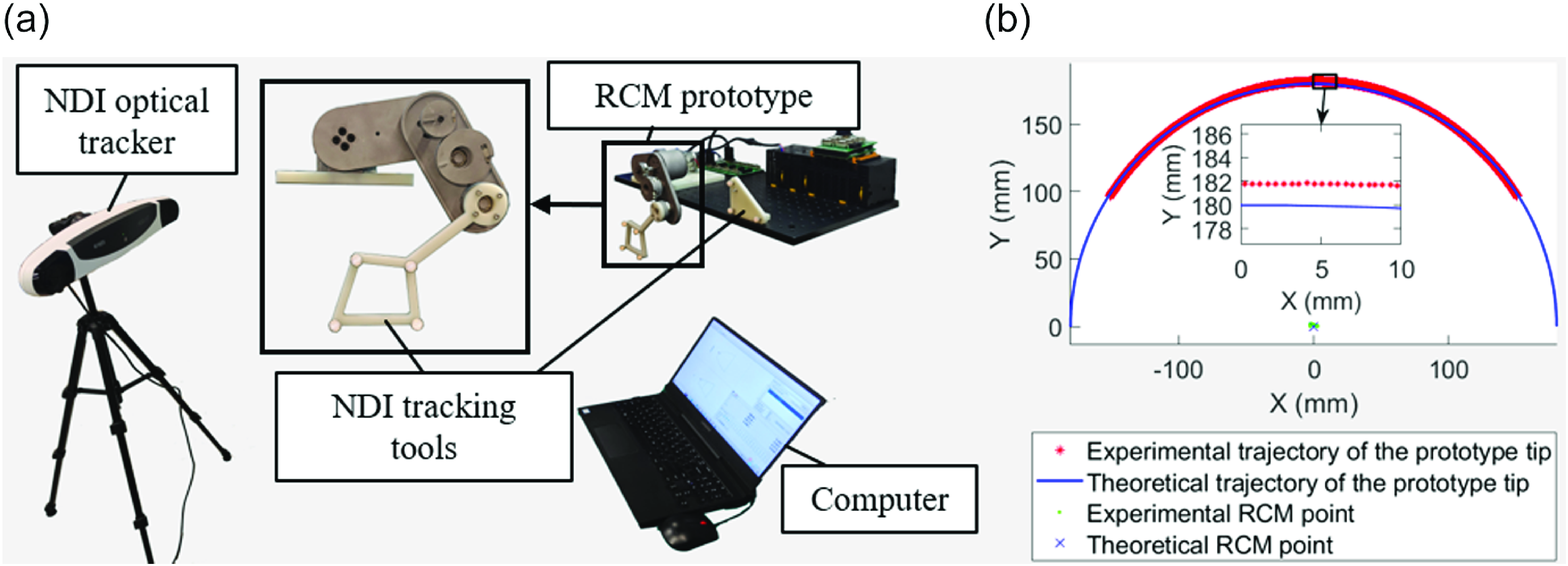
A preliminary experiment is conducted to validate the RCM characteristics of the proposed mechanism. The experimental setup primarily involves the RCM prototype, an NDI optical tracking system, and a computer, as illustrated in Figure 13(a). The NDI optical tracking system is employed to record the end trajectory and the positions of the RCM points during the prototype’s motion, and the results are presented in Figure 13(b).
Trajectory test. (a) Experimental setup. (b) Trajectory of the RCM mechanism.

As proved in the figure, the experimental trajectory of the prototype aligns well with the theoretical trajectory of the compact RCM mechanism, with a maximum deviation of approximately 2 mm. While this error is still slightly higher than that of some commercial surgical systems currently in use, it remains within a comparable range. For example, the positional error of the robotic arm in the da Vinci surgical system is approximately 1–2 mm after kinematic calibration [Reference Ferguson, Cai, Reed, Siebold, De, Herrell and Webster37]. In addition, the current prototype is only designed to validate the RCM motion characteristics, rather than for final application in MIS. Therefore, a simplified manufacturing (3D printing) and assembly process is adopted for the prototype. In future implementations intended for MIS applications, higher-precision manufacturing and assembly techniques will be employed to improve the accuracy.
6.2. Stiffness measurement
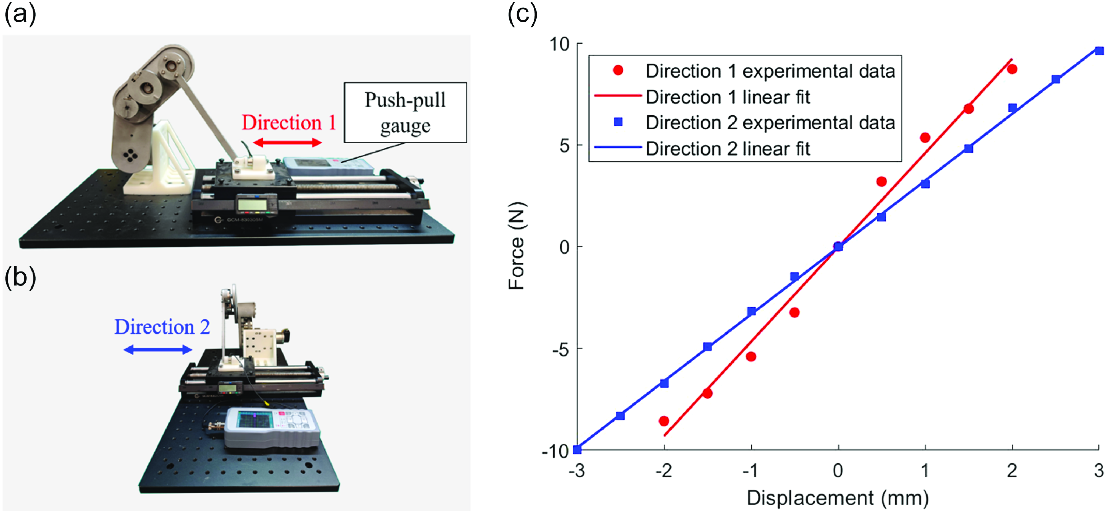
The stiffness of the prototype is measured to verify the potential of our mechanism to provide sufficient operating force for MIS applications. The experimental setup is shown in Figure 14(a) and Figure 14(b). In the setup, a push-pull gauge for force measurement is mounted on a linear displacement platform and connected to the tip of the prototype. Forces are applied to the prototype by moving the linear displacement platform in two directions (within the motion plane of the mechanism and perpendicular to the motion plane) with an incremental step of 0.5 mm. The translational distance of the linear displacement platform and the force measured by the push-pull gauge are recorded to obtain the force-displacement relationship, as shown in Figure 14(c). The measured data are fitted using the least squares method to obtain the force–displacement curves, and their slopes are calculated to determine the stiffness of the mechanism, which is 4.63 N/mm in the motion plane and 3.28 N/mm perpendicular to the motion plane. This is sufficient for MIS robots to manipulate soft tissues, where the operating force typically does not exceed 5 N [Reference Peirs, Clijnen, Reynaerts, Van Brussel, Herijgers, Corteville and Boone38, Reference Hong and Jo39].
Stiffness measurement. (a) Experimental setup in the first direction. (b) Experimental setup in the second direction. (c) Measured force displacement curves.

7. Conclusions and future work
To reduce the footprint of the RCM mechanism in MIS robots, this study proposes a compact RCM mechanism based on the coupling of three rotational motions realized by a nonlinear transmission system. The coupling relationship and ROM of the proposed mechanism are analyzed, followed by the design of the nonlinear transmission system. A prototype of the proposed mechanism is fabricated, whose footprint is compared with that of a regular parallelogram-based RCM mechanism with three indicators. An error model is established to account for the errors induced by the elasticity of the transmission belts, considering both circular and non-circular pulleys. The feasibility of the proposed mechanism is verified through preliminary experiments. The results indicate that our RCM mechanism is more compact than the parallelogram-based RCM mechanism and has a smaller footprint, suggesting promising application prospects in MIS robots.
In the future work, we will conduct fatigue tests on the multiple steel belts employed in the transmission system to estimate their service life and optimize the structural design to facilitate easier replacement. In addition, we will incorporate additional rotational and translational joints into the mechanism to meet the DOF requirements of MIS. Standardized exchange interfaces will also be developed to accommodate different types of surgical instruments, thus further promoting the adaptability of the proposed mechanism to a broader range of MIS scenarios.
Author contributions
Haixin Zhao and Jinhua Li conceived and designed the study. Jianchang Zhao and Yue Yu made the prototype for experiment. Haixin Zhao and Jianchang Zhao wrote the paper. Jinhua Li reviewed and edited the manuscript.
Financial support
This work was supported by the National Key Research and Development Program of China under Grant 2022YFB4702800.
Competing interests
The authors declare no conflicts of interest exist.
Ethical approval
Not applicable.