Introduction
Now-a-days, most of the wireless communication systems preferred planar antennas for different applications, because they are compact, low profile, light-weight, and can provide omnidirectional and directional radiation characteristics depending on the application. Furthermore, with the introduction of different wireless communication standards, there is a need to design antennas, which can operate at multiple frequency bands and can easily be integrated into a single unit. For this purpose, different antenna designs with super wideband (SWB) characteristics have been reported in the literature.
In [Reference Liu, Zhong and Esselle1], the authors improved the bandwidth of co-planar waveguide (CPW) fed printed elliptical antenna by incorporating semi-ring with the tapered feed line. They achieved an impedance bandwidth of 23.08 GHz and a ratio bandwidth of 23:1. The authors in [Reference Liu, Zhong and Esselle1] also presented another elliptical patch antenna design to get SWB performance [Reference Liu, Esselle, Hay and Zhong2]. In this design, they used a trapezoidal ground on the other side of the substrate and achieved measured impedance bandwidth in the frequency range of 1.08–27.4 GHz. The same technique was presented in [Reference Samsuzzaman and Islam3] with a semi-circular shaped patch. In [Reference Gorai, Karmakar, Pal and Ghatak4], a propeller-shaped CPW-fed planar antenna design was presented for SWB applications. The authors modified circular shape into a propeller shape to achieve an impedance bandwidth from 3 to 35 GHz. The presented antenna also provides almost omni-directional radiation characteristics in the SWB range. In [Reference Liu, Esselle, Hay and Zhong5], an asymmetric planar antenna design was presented for SWB characteristics. The antenna structure consisted of a modified rectangular patch and an asymmetric trapezoid ground plane. From the presented configuration, the authors observed a ratio bandwidth of 31:1 in the frequency range of 1.05–32.7 GHz. Dorostkar et al. [Reference Dorostkar, Islam and Azim6] presented a novel circular-hexagonal planar antenna for extremely wideband applications. Their presented design consisted of hexagonal slots removed from the circular patch antenna. From the presented design, the authors achieved a ratio bandwidth of 20.4:1 in the frequency range of 2.18–44.5 GHz. In [Reference Manohar, Nemani, Kshetrimayum and Gogoi7], a novel trapezoidal antenna with a tapered feed line was presented for SWB characteristics. According to the authors, the designed antenna was operating from 3.1 to 94.7 GHz and has a ratio bandwidth of 31:1, but it was validated up to 24 GHz.
A compact hut-shaped planar antenna design was presented in [Reference Tahir and Naqvi8] for SWB performance. The designed antenna was composed of a hut-shaped patch radiator with a diamond-shaped slot in its center and a partial ground plane with a rectangular notch. Results showed that the antenna had an impedance bandwidth of 184.5% with a ratio bandwidth of 24.8:1. In [Reference Van, Kwon and Hwang9], a planar loop antenna design was presented for SWB characteristics. The authors utilized the asymmetric co-planar strip with a hexagonal loop strip and achieved impedance bandwidth from 1.18 to 49.22 GHz. In [Reference Okas, Sharma and Gangwar10], a modified rectangular planar antenna design was presented for SWB characteristics. A wideband response in the frequency range of 0.96–13.98 GHz was achieved by modifying the conventional rectangular patch through a circular base fed using a tapered microstrip feed line. Furthermore, the elliptical ground plane was utilized to reduce the capacitive effects and to nullify the antenna reactance. They also presented a modified square monopole antenna in [Reference Okas, Sharma and Gangwar11] for SWB performance with stable radiation characteristics.
Torres et al. [Reference Figueroa-Torres, Medina-Monroy, Lobato-Morales, Chávez-Pérez and Calvillo-Téllez12] designed and presented a novel fractal antenna for SWB applications. The antenna design consisted of a complementary Sierpinski Gasket triangle surrounded by two semi-circular sectors. For improved impedance bandwidth, the authors modified the ground plane by incorporating slots at the corners and the center. From the presented design, they achieved a ratio bandwidth of >15:1 from 1.68 to 26 GHz. In [Reference Rahman, Islam, Mahmud and Samsuzzaman13], a compact crescent-shaped planar antenna was designed and presented for SWB response. The designed antenna offered ratio bandwidth of 11.6:1 in the frequency range of 2.5–29 GHz. In [Reference Rafique, Ahmed, Hassan and Khalil14], another modified planar elliptical antenna was presented for SWB applications. The design technique was the same as presented in [Reference Liu, Esselle, Hay and Zhong2], but the antenna was compact. In [Reference Rafique and Din15], a beveled-shaped SWB antenna design was presented. The authors utilized two ground planes with a tapered feed line to achieve wide impedance bandwidth from 0.3 to 20 GHz.
In [Reference Rahman, Cao, Ullah and Khalil16], the authors designed a trapezoidal-shaped planar antenna for SWB applications. They utilized a tapered microstrip line with circular ground and showed resonance from 1.42 to 90 GHz. Okan [Reference Okan17] presented a octagonal-ring-based planar monopole antenna for SWB applications. To enhance the impedance bandwidth, the author utilized a stub on the top right corner of the octagonal-ring patch radiator. Through the presented configuration, a bandwidth of 28.55 GHz was achieved from 2.59 to 31.14 GHz. Singhal et al. [Reference Singhal, Jaiverdhan and Singh18] presented an elliptical monopole-based fractal antenna for SWB performance. The fractal geometry was achieved by arranging three iterations elliptical patch radiators in a tree-shaped manner. According to the authors, the designed antenna operates in the frequency range of 0.65–35.61 GHz. The above-mentioned antenna designs provided wide impedance bandwidth but they were large or consisted of complex structures. So, there is a need to design an antenna, which should be small in size and it can also provide wide impedance bandwidth. Furthermore, the geometry of the antenna should be simple so that it can easily be fabricated by utilizing low-cost fabrication techniques, e.g. chemical etching.
For this purpose, in this paper, a compact and simple planar elliptical antenna design has been presented for SWB performance. The proposed antenna consists of an elliptical patch radiator fed using a modified CPW tapered semi-ring microstrip feed line. Simulated results offer an impedance bandwidth of 180.66% from 1.27 to 25 GHz, while measurements show that the designed antenna operates in the frequency range of 1.76–24.7 GHz. The comparison of the proposed antenna is done with previously presented designs, and it is observed that the proposed design is compact in size than the designs presented in [Reference Liu, Zhong and Esselle1–Reference Singhal, Jaiverdhan and Singh18]. It can also be observed from the presented results that the proposed antenna is a suitable candidate for many wireless communication applications such as cellular communication, WiMAX, Wi-Fi/WLAN, radar communication, satellite and defense communication, and millimeter-wave communications, etc.
Proposed antenna structure
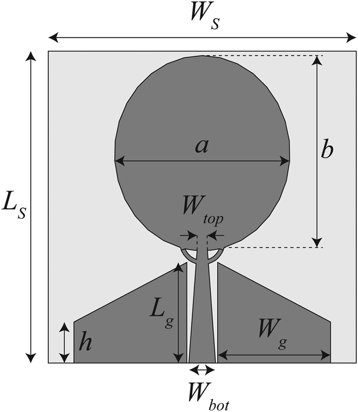
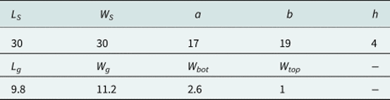
Figure 1 illustrates the proposed SWB antenna design, and the overall optimized design parameters are listed in Table 1. It is designed and fabricated on Rogers RT/Duroid 5880 having ɛ r = 2.2 and h = 1.57 mm. The overall dimensions of the antenna are W S × L S having electrical length 0.13λ × 0.13λ, where λ corresponds to the wavelength at the lowest resonant frequency. The proposed antenna comprises an elliptical patch radiator and a modified CPW tapered semi-ring feed line. The CPW feed technique is used due to its several advantages, e.g. low losses, co-planar nature, and ease of fabrication, etc. The feed line's width is linearly changed from 50 Ω (W bot) to 100 Ω (W top) to get maximum impedance matching at the radiation element, where the length of the tapered microstrip feed line is 10 mm. The gap between the feed line and the ground plane is taken to be uniform having value 2.8 mm. The semi-ring structure connected with the elliptical patch radiator also plays an important role in achieving wide impedance bandwidth.
Schematic of the proposed CPW-fed planar elliptical SWB antenna.

Optimized design parameters of the proposed SWB antenna (in mm)

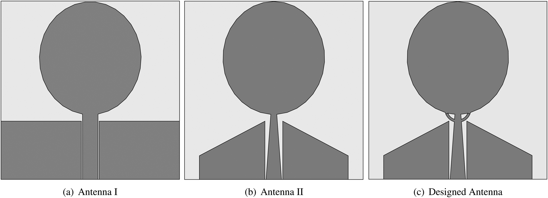
The design steps of the proposed SWB antenna are illustrated in Figs 2(a)–2(c). First, a conventional CPW-fed planar elliptical monopole antenna, shown in Fig. 2(a), is considered. The dimensions of the elliptical patch radiator are calculated using below-mentioned design expressions [Reference Ray19].

where f l is the lowest resonant frequency in the operating bandwidth, L denotes the height of the patch radiator, which is taken same as that of an equivalent cylindrical monopole, r is the radius of an equivalent cylindrical monopole antenna, and p is the length of the microstrip feed line. Here, k belongs to the effective dielectric constant (ɛ eff), which arises due to the presence of dielectric. For elliptical patch radiator, the values of L and r are realized in terms of its semimajor axis (A) and semiminor axis (B), which are given as follows [Reference Ray19]:

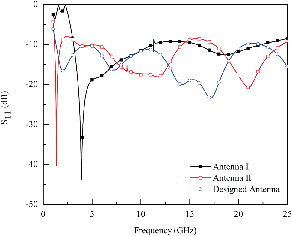
After calculating the required parameters, the conventional CPW-fed planar elliptical antenna is simulated in Ansys HFSS and its respective S 11 characteristics are shown in Fig. 3. From the figure, it is observed that Antenna 1 is operating from 3.1 to 11.3 GHz. For improved bandwidth, the ground plane shape is changed to a triangular shape and the microstrip feed line is changed to tapered microstrip line as shown in Fig. 2(b). The modified tapered CPW line reduces the inductive effect of the patch radiator by initiating a capacitive effect, which results in a purely resistive impedance. This modification tends to achieve wide impedance bandwidth as shown in Fig. 3, but the design of antenna 2 provides some impedance mismatch in the band of interest. To reduce impedance mismatch, two side branches of semi-ring shape have been connected with the elliptical patch radiator as shown in Fig. 2(c). It has been described that the use of multiple symmetrical feed lines to a planar antenna can support the excitation of vertical characteristics mode and efficiently stimulate the vertical current component on the radiating patch, leading to enhancement in impedance bandwidth [Reference Wong, Wu and Su20]. Therefore, the use of a semi-ring structure with the antenna structure provides impedance bandwidth from 1.27 to 25 GHz as shown in Fig. 3.
Geometry of different antennas: (a) conventional CPW-fed planar elliptical antenna, (b) modified CPW tapered line fed planar elliptical antenna, (c) modified CPW tapered semi-ring fed planar elliptical antenna.

Simulated S 11 of different antenna designs.

Results and discussion
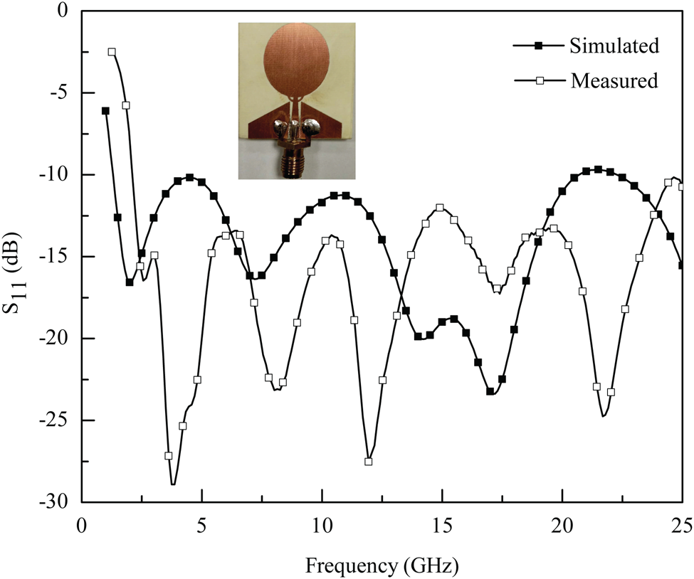
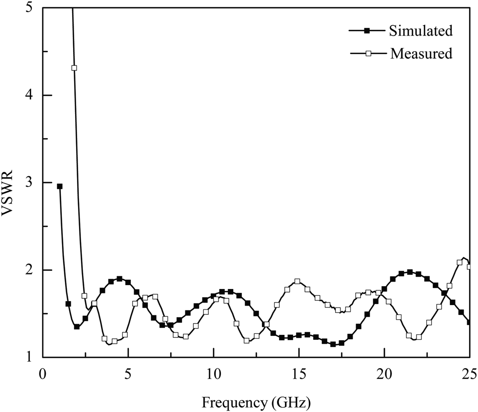
Figure 4 shows simulated and measured S 11 characteristics of the proposed antenna, while simulated and measured VSWR results are illustrated in Fig. 5. According to the simulation, shown in Figs 4 and 5, the designed antenna operates in the frequency range of 1.27–25 GHz. The fabricated prototype, shown in the inset of Fig. 4, has been characterized using Agilent Technologies Power Network Analyzer (PNA-X) N5245B in the frequency range of 1–25 GHz. From Figs 4 and 5, it has been noted that the measured and simulated S 11 and VSWR results are in good agreement. The measured results offer an impedance bandwidth of 22.94 GHz from 1.76 to 24.7 GHz. The observed discrepancies could arise due to the imperfect soldering of SMA connector, fabrication tolerances, and scattering measurement environment.
Simulated and measured S 11 of the proposed SWB antenna (inset of figure shows fabricated antenna prototype).

Simulated and measured VSWR results of the proposed SWB antenna.

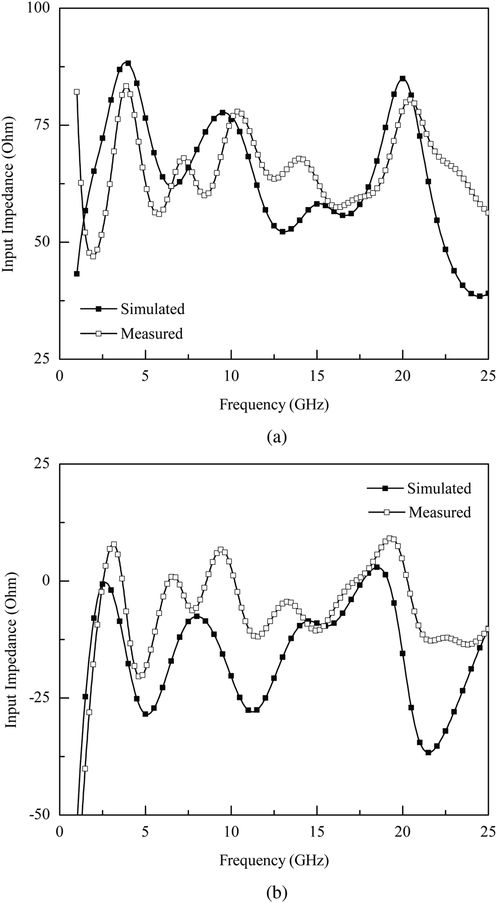
The simulated and measured input impedance results of the proposed SWB antenna are shown in Figs 6(a) and 6(b) in terms of its real (Re) and imaginary (Im) parts. It has been observed from the figure that the input impedance values are fluctuating around ≈ 50 Ω and 0 Ω, which results in the overall input impedance of 50 Ω.
Simulated and measured input impedance of the proposed SWB antenna: (a) Re, (b) Im.

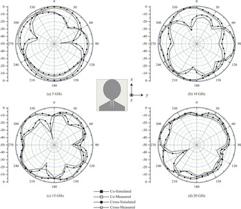
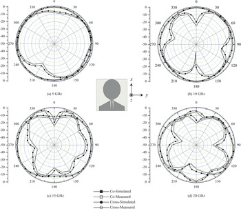
The simulated and measured E- (ϕ = 0°) and H-plane (ϕ = 90°) radiation properties of the proposed SWB antenna are depicted in Figs 7 and 8. The radiation patterns are realized in terms of both co-polarization and cross-polarization components. It has been observed that for resonant frequencies 5 and 10 GHz, the antenna has a typical monopole (eight shaped) like patterns for E-plane and omni-directional patterns for H-plane. For higher frequencies, omni-directional radiation characteristics with some distortions are observed for both the planes. The cross-polarization component is less compared to the co-polarization component. However, for some angles, the level of cross-polarization patterns is high, which is due to the excitation of higher-order modes at higher frequencies. Moreover, the thickness of the substrate is less than the quarter wavelength therefore, a 180° phase difference is introduced between the reflected surface waves and the waves that impinge on the substrate. Due to this phenomenon, destructive interference will be produced, which results in the increment of the cross-polarization field. Despite the higher cross-polarization field, the radiation characteristics of the proposed antenna are robust across the operating bandwidth.
Simulated and measured E-plane radiation characteristics of the proposed SWB antenna.

Simulated and measured H-plane radiation characteristics of the proposed SWB antenna.

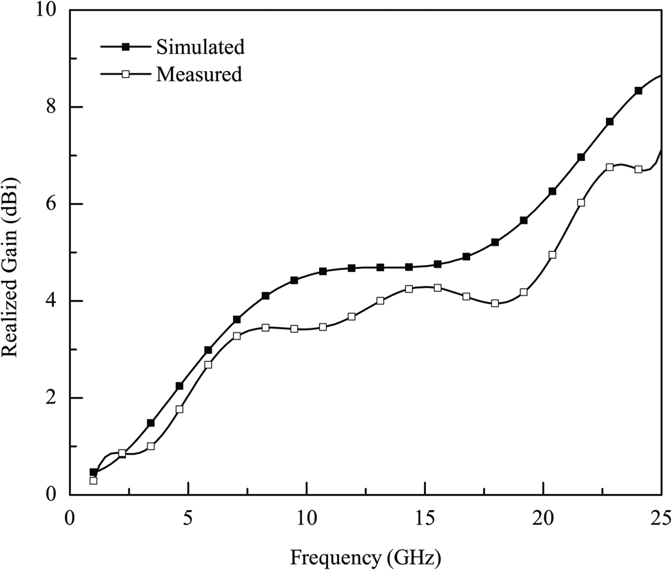
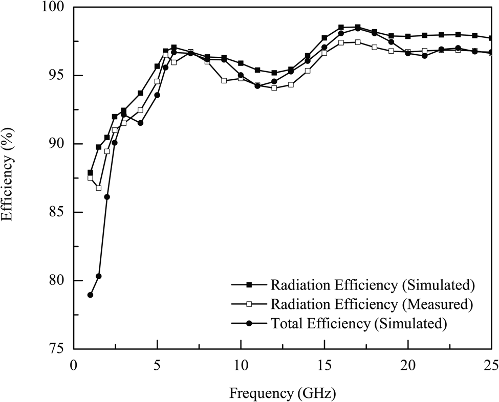
The simulated and measured realized gain results of the designed SWB antenna are shown in Fig. 9. It has been observed that the gain is increasing with the increase in frequency. The minimum gain value is noted to be 0.35 dBi at 1.27 GHz, while the maximum gain value is 7.08 dBi at 25 GHz. Moreover, the average gain in the entire operating bandwidth is 3.8 dBi. Figure 10 illustrates antenna efficiency for the entire operating bandwidth. From the figure, one can observe that the proposed antenna exhibits simulated average radiation and total efficiencies of 95.77 and 94.22%, respectively; while measured radiation efficiency is ≈94.69%.
Simulated and measured realized gain of the proposed SWB antenna.

Simulated and measured radiation efficiency and total efficiency of the proposed SWB antenna.

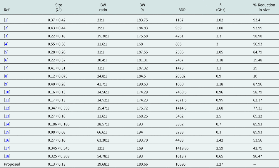
The comparison between proposed and previously presented SWB antenna designs is given in Table 2. The antenna structures are compared in terms of their electrical dimensions, bandwidth ratio, percentage bandwidth, bandwidth dimension ratio (BDR), and lower operation frequency (f L). The term BDR indicates that how much operating bandwidth in percentage can be provided by the antenna per unit electrical area. However, it is established that the value of BDR should be high to validate the advantages of the presented structure over other existing designs. Mathematically, it can be expressed as [Reference Chen, Sim and Row21]:

Comparative analysis of proposed antenna design with previously presented antennas

From Table 2, one can observe that the proposed antenna exhibits better performance in terms of bandwidth ratio, percentage bandwidth, BDR, and f L. It has also been noted from Table 2 that the proposed antenna design offers 10 to 96.47% size reduction compared to other reported designs.
Conclusion
A compact CPW-fed planar antenna design has been presented for SWB applications. The presented design consists of an elliptical-shaped patch radiator fed using a modified 50 Ω CPW-fed tapered microstrip line. It has been described that the use of a semi-ring structure with a tapered feed line tends to achieve enhanced impedance bandwidth. Therefore, from simulation results, it has been noted that the proposed antenna offers an impedance bandwidth of 23.73 GHz from 1.27 to 25 GHz with a ratio bandwidth of 19.68:1, while measured results show an impedance bandwidth of 22.94 GHz from 1.76 to 24.7 GHz. Furthermore, the designed antenna exhibits good radiation characteristics and offers acceptable gain and efficiency for the entire operating bandwidth. From the presented results, one can say that the designed antenna is a good candidate for cellular applications, WiMAX, Wi-Fi/WLAN/Wi-Fi, radar communication, satellite and defense communication systems, and millimeter-wave communications.
 Umair Rafique received his B.S. degree in Electronic Engineering from Mohammad Ali Jinnah University (MAJU), Karachi, Pakistan in 2011 and the M.S. Electronic Engineering degree in 2017 from Capital University of Science and Technology (CUST), Pakistan. From 2010 to 2013, he worked with the Research Group of Microelectronics and FPGAs at MAJU as a Research Associate and Research Fellow. In 2013, he joined AKSA Solutions Development Services (AKSA-SDS) as an RF Design Engineer, where he was responsible for the design and implementation of RF front-ends for airborne applications. In 2015, he joined the Research Group of Microelectronics and RF Engineering at CUST as a Research Associate. His research interests are in antenna design, frequency selective surfaces, microelectronics, and RF Engineering. He authored 38 research papers in reputed international journals and conferences. He is a member of the Institution of Electrical and Electronics Engineering (IEEE), USA.
 Sami ud Din received his B.S. degree in Electrical Engineering from Federal Urdu University of Arts, Science and Technology, Islamabad, Pakistan in 2009, the M.S. degree in Electronic Engineering (Control Systems) from Mohammad Ali Jinnah University, Karachi, Pakistan in 2012 and the Ph.D. degree in Electrical Engineering with Specialization of Control Systems from Capital University of Science and Technology (CUST), Islamabad, Pakistan in 2019. Currently, he is associated with the Department of Electrical Engineering, Namal Institute, Mianwali, Pakistan as an Assistant Professor. His research interests include antenna design, chaotic systems, and robotics.
 Hisham Khalil received his B.S. Electrical Engineering degree in 2007 and the M.S. Electronic Engineering degree in 2012 from The University of Lahore, Lahore, Pakistan. Currently, he is working toward his Ph.D. in Electromagnetics and Microwave Engineering from Capital University of Science and Technology (CUST), Pakistan. His research interest includes analysis and design of printed antennas, conformal arrays, and electromagnetic circuits.