I. INTRODUCTION
Printed microstrip antennas are very well known in the field of microwave technology. Owing to the ease of fabrication, low cost, and wide choice of designs, microstrip technologies for antennas continue to be a field of active research. To make the data transmission independent of orientation of the transmitting and receiving antennas for wireless communications, circularly polarized (CP) antennas are preferred. Based on the slits [Reference Sharma and Gupta1–Reference Nasimuddin and Chen5], stubs, and slot-loaded [Reference Nasimuddin and Chen6, Reference Nasimuddin and Chen7] techniques, several single-feed asymmetrical structures are suggested for CP operation. However, the reported 3-dB axial ratio (AR) bandwidth of all these approaches is very narrow (<1%). Wide AR bandwidth is possible using the complex feeding mechanisms such as aperture [Reference Chen8, Reference Lai, Mak and Chan9] and proximity-coupled [Reference Tong, Lacotte and Huang10] techniques. However, broadband CP antennas with a simple probe feed have not been adequately reported in open literature.
Over the past decade, metamaterial-based antennas have been extensively explored to improve the radiation characteristics. Design of antenna elements with high front-to-back ratio can be achieved through metal-backed perfect electric conductor (PEC) or high dielectric constant super substrates [Reference Colburn and Rahmat-Samii11]. However, most of the electromagnetic (EM) energy is trapped between the metallic patch and the ground plane. This leads to the narrow bandwidth operation and low efficiency. To overcome this problem, high impedance or artificial perfectly magnetic conductor (PMC) surfaces are developed. The PMC substrates are usually constructed from resonance structures. So PMC surface absorbs most of near-field EM energy, which results in low antenna efficiency. To overcome the problems faced by high dielectric and PMC surfaces, artificial reactive impedance surface (RIS) technique has been evolved. An RIS reduces the mutual coupling between the radiating patch and ground plane and provides broadband operation than PEC and PMC surfaces. Antenna miniaturization and bandwidth enhancement using RIS for planar antennas is first introduced by Mosallaei and Sarabandi [Reference Mosallaei and Sarabandi12]. Design of compact broadband Ultra High Frequency patch antenna on an RIS is also proposed by Buerkle and Sarabandi [Reference Buerkle and Sarabandi13]. Implementation of slot-loaded patch over RIS aiming broadband CP operation is suggested by Bernard et al. [Reference Bernard, Chertier and Sauleau14]. The asymmetric, symmetric slotted and slit microstrip patch antennas over RIS for CP bandwidth enhancement are published by Agarwal and Nasimuddin [Reference Agarwal, Nasimuddin and Alphones15]. However, implementation of fractal structure over RIS has not been attempted so far. In the present work, both fractal and RIS concepts are combined to generate CP radiation over a broadband with a simple coaxial probe feed.
Fractals concept has been applied for the microstrip antennas for broadband and multiband applications [Reference Balanis16]. Fractal geometries can best be described and generated using an iterative process that leads to self-similar and self-affine structures [Reference Borja and Romeu17]. In this paper, boundary fractals are applied to the edges of a square patch and the corresponding structures are implemented over RIS for broadband CP radiation. The proposed antennas are compact with the use of fractal curves as boundaries. Investigations on the simple Koch structure, RIS with square elements and fractal elements are carried out in a systematic way for compact and broadband CP radiation. The 10-dB return loss bandwidth for the proposed antennas covers the frequency bands of UMTS, LTE2300, WLAN, Bluetooth, Wi-Fi, and Wi-Max applications.
II. PROPOSED ANTENNA DESIGN
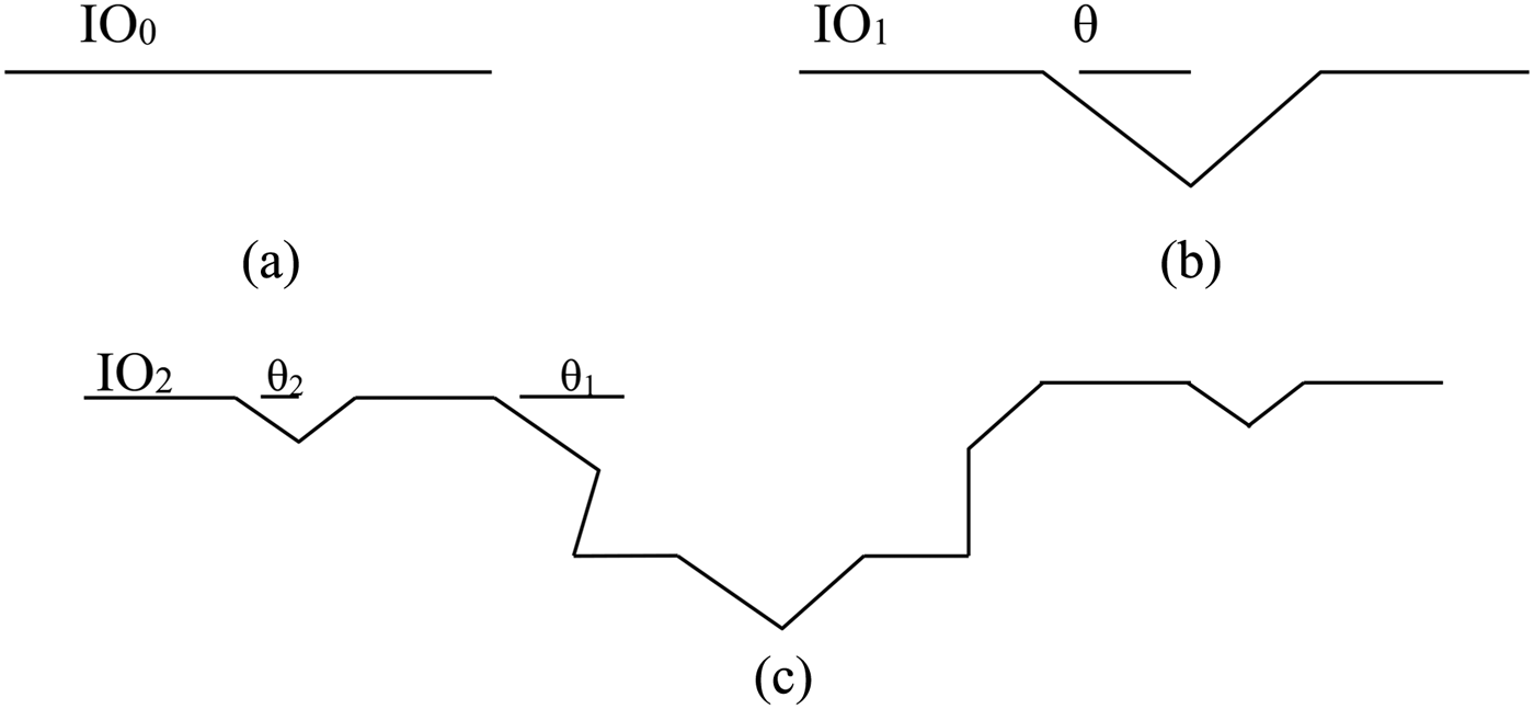
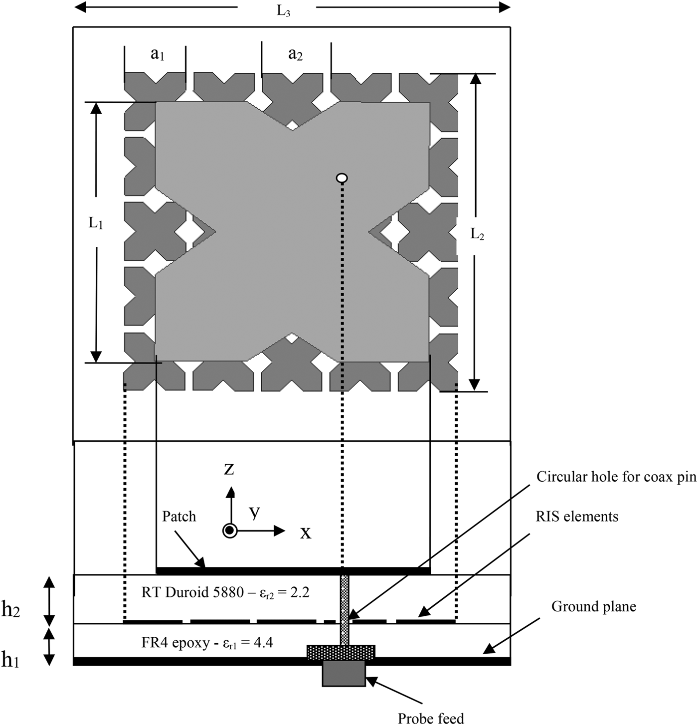
The generation process of the Koch fractal curve for different iteration order (IO) is shown in Fig. 1, where θ is the indentation angle. End-to-end length of all the patches is considered as 36 mm, so that antennas resonate in 2–3 GHz frequency and are useful for ISM band wireless applications. Side and top views of antenna geometry are shown in Fig. 2.
Generation process of the Koch fractal curve.

Side and top views of the proposed antenna.
The design procedure of the proposed structures is given below in three steps:
(1) Initially single-layer asymmetrical fractal boundary antennas are designed to generate two orthogonal modes of same amplitude and 90° out of phase for CP operation [Reference Reddy and Sarma18]. This can be achieved by replacing sides of the square patch with two asymmetrical fractal curves along the two orthogonal axes. Asymmetry in the fractal curves can be obtained by changing the indentation angles θ along the x- and y-axes. Here IO one and two Koch fractal boundary antennas are studied. All structures are placed on a metal backed Rogers 5880 substrate of thickness 3.2 mm.
(2) RIS elements are optimized.
(3) Single-layer fractal antennas are implemented over an RIS substrate with 5 × 5 square and fractal RIS elements.
III. SIMULATION RESULTS
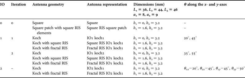
The proposed antenna consists of an Koch IO1/IO2 patch radiator printed on top of a dual layer (FR4 and Rogers 5880, tan δ = 0.02) substrates with thicknesses of h 1 = 1.6 mm and h 2 = 3.2 mm, in which the ground plane lies at the bottom of the structure and RIS is printed at the interface between two dielectric layers. This RIS layer comprises an array of 5 × 5 square metallic unit-cell patches printed periodically along the x- and y-axes. The feed arrangement is by a coaxial probe along the diagonal axis. A circular region of 1.6 mm radius is removed from RIS layer, so that probe does not come in contact with the metal RIS units. The dimensions of all the proposed antennas are listed in Table 1. The HFSS tool is used to design and optimize parameters of Koch curve for better CP. In this tool using the optimetrics analysis setup, feeding point is optimized. The optimetrics analysis setup aids to identify the optimum feeding point by indicating the 3-dB CP bandwidth and gain at various locations in a neighborhood. The feed location along the diagonal axis, at which the maximum 3-dB CP bandwidth and gain above 4-dBi obtained is considered as the optimized feeding point.
Parameters of simulated antennas.
A) Single-layer fractal patch
Initially the square patch with side length 36 mm is considered for linear polarization. In the design of CP antenna, the indentation angles of fractal curve along the x- and y-directions are altered as shown in Fig. 3, i.e. the electrical length along the two perpendicular directions of the patch are different. This slight difference in indentation angles as given in Table 1 along the x- and y-axes, generates two orthogonal modes. The two degenerate orthogonal modes TM01 and TM10 are also formed due to feeding the patch antenna along the diagonal axis at a precise matching position. The simulated return loss curves of the single-layer antennas are portrayed in Fig. 4. It is observed that with the increase of indentation angles and IO of the fractal curve, frequency band moves left, which is due to the increment of electrical length of the patch.
Single-layer fractal boundary antennas geometries: (a) square patch, (b) IO1 koch1, (c) IO1 koch2, and (d) IO2 koch1.
Simulated return loss curves of single-layer fractal boundary antennas.
B) Optimization of RIS elements
Initially the square RIS IO1 koch1 antenna is examined over different RIS layers. By keeping the FR-4 of thickness 1.6 mm as bottom layer and RT/Duroid 5880 of thickness 3.2 mm as top layer, simulations are repeated for 4 × 4, 5 × 5, and 6 × 6 RIS elements. The generated 5-dB VSWR bandwidths are 69, 81, and 51 MHz for 4 × 4, 5 × 5, and 6 × 6 RIS elements. Because of this slightly higher bandwidth, 5 × 5 RIS elements structure is considered for further simulations. The VSWR plots for various cases are pictured in Fig. 5.
VSWR plots of square RIS IO1 koch1 antenna for 4 × 4, 5 × 5, and 6 × 6 RIS elements.
C) Dual-layer fractal antennas with square RIS elements
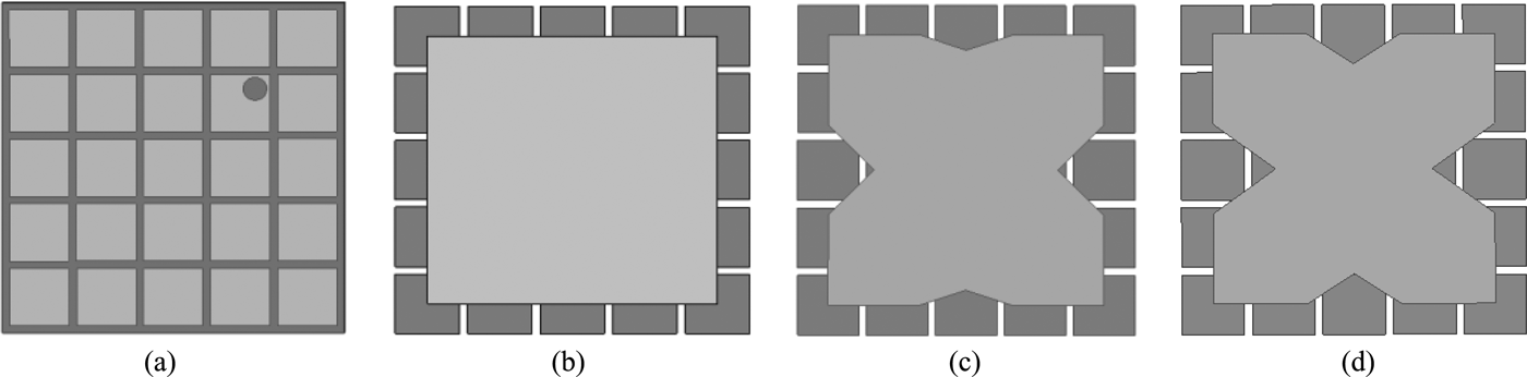
In order to enhance the 3-dB CP bandwidth of single-layer Koch structures, an RIS method is employed. The PEC ground plane of RIS surface after a thickness exhibits inductive nature and which comes in parallel combination with capacitance created by the RIS patches on the substrate, thus forming the LC parallel circuit. Here square elements of size 8 × 8 mm are considered as RIS elements. The RIS is an engineered meta-substrate that allows miniaturization, while reducing coupling between the antenna and its ground plane. Therefore, an antenna printed on an RIS is capable of providing a broadband response, while maintaining compact size and high radiation efficiency. The PEC ground plane of single-layer antennas is replaced with the 5 × 5 square elements of RIS substrates as shown in Fig. 6, to generate higher bandwidth. The return loss curve with two orthogonal modes for CP radiation similar to Fig. 4 is generated from single-layer fractal antennas get stretched when the RIS method is applied. A circular hole is made for probe feeding. Simulated return loss curves of dual-layer square RIS elements antennas are pictured in Fig. 7. It is observed from summarized Table 2 that RIS antennas with fractal patch generates higher bandwidth than the RIS antenna with square patch.
Dual-layer fractal boundary antennas with square RIS elements: (a) top view of metal patched 5 × 5 array forming RIS, (b) square RIS square patch, (c) square RIS IO1 koch1, and (d) square RIS IO1 koch2.
Simulated return loss curves of dual-layer square RIS elements antennas.
The summarized simulation results of the proposed antennas.
D) Dual-layer fractal antennas with fractal RIS elements
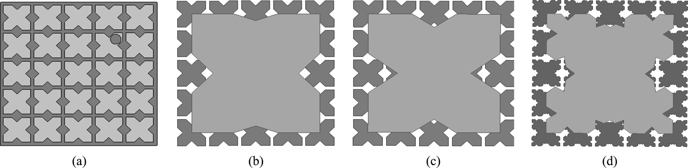
As mentioned in the previous section RIS is more like an LC resonant circuit. So by changing the thickness of the RIS substrate and optimizing the elements of the patch array, radiation properties of the antenna can be improved. An RIS is a printed capacitive layer separated from a metallic ground plane by a dielectric substrate layer. The resonant frequency of the surface depends on the value of the capacitive elements, the distance between the capacitive layer and the metallic surface, and the permittivity of the dielectric layer. To enhance the performance of the CP radiation over a broadband, square RIS elements are replaced with optimized fractal elements as shown in Fig. 8 and corresponding return loss curves are given in Fig. 9.
Koch fractal boundary antennas over RIS with optimized fractal elements: (a) metal-backed RIS with 5 × 5 fractal elements, (b) fractal RIS IO1 koch1, (c) fractal RIS IO1 koch2, and (d) fractal RIS IO2 koch1.
Simulated return loss curves of Koch fractal boundary antennas over optimized fractal RIS.
E) AR plots
It is observed from the simulated AR as shown in Fig. 10, that the IO1 iteration 1 antenna produces best AR of nearly 0 dB at center frequency of 2.45 GHz and optimized fractal RIS generates more 3-dB AR bandwidth than others by compromising the best AR value at the center frequency to 1.4 dB. For the best operation of CP radiation 3-dB AR values are considered within the 10-dB return loss bandwidth range. The 3-dB AR bandwidth of fractal RIS IO1 koch1 is 1.81% more than the square RIS IO1 koch1 and 4.84% more than simple Koch designed with conventional PEC ground plane. AR versus frequency plots of IO2 are pictured in Fig. 11. It is noted from the summarized results listed in Table 2 that RIS-based antennas resonate at lower frequencies than single-layer antennas, thus showing antenna miniaturization. As a result, RIS improves two major drawbacks of conventional ground planes: (1) impedance matching can be done over broadband; and (2) miniaturization of the antenna size. The simulated surface current distribution of fractal RIS IO1 iteration1 at 2.30 GHz is pictured in Fig. 12.
Simulated AR of IO1 antennas.
Simulated AR of IO2 antennas.
The simulated surface current distribution of fractal RIS IO1 iteration1 at 2.30 GHz: (a) at 0°, (b) at 90°, (c) at 180°, and (d) at 270°.
VI. MEASURED RESULTS AND DISCUSSIONS
In the simulations section, from Table 2 it is observed that Koch with fractal RIS elements IO1 iteration 1 generates more 3-dB CP bandwidth, which is due to high optimized asymmetry along the two orthogonal curves along the x- and y-axes. To validate the hypothesis made pertaining to the proposed antennas; the best performer antenna fractal RIS IO1 iteration1 is fabricated and tested experimentally. The antenna consists of two layers. The bottom layer has fractal RIS elements that are printed on the 1.6-mm thickness FR4 epoxy of dielectric constant 4.4. The top layer consists of Koch fractal with two asymmetrical fractals curves along the two orthogonal directions is printed on 3.2 mm thickness RT/Duroid 5880 of dielectric constant 2.2. The two layers are stacked using a dielectric adhesive and the fabricated antennas are shown in Fig. 13. The comparison of the simulated and the measured results of the proposed antenna are portrayed in Fig. 14. The deviations appearing between simulated and experimental results are due to tolerance levels during the fabrication process of the antenna.
Prototype of fabricated antennas. (a) RIS. (b) Fractal RIS IO1 iteration1 Koch antenna
Comparison of simulated and measured results of fractal RIS IO1 iteration1: (a) return loss characteristics, (b) axial ratio, and (c) gain.
The measured radiation patterns of fabricated fractal RIS IO1 at 2.3 GHz in the horizontal plane (HP) and vertical plane (VP) are shown in Fig. 15. The deviation between these two radiation patterns gives the AR in that direction. The measured 3-dB AR and 10-dB return loss bandwidths are 7.45 and 50.35%, respectively. The proposed fractal RIS IO1 iteration generates high 3-dB AR bandwidth than other antennas because of the high optimized asymmetry along the two perpendicular directions for good CP radiation. The proposed structure generates higher 3-dB AR CP bandwidth with a simple single probe feed by combing fractals and RIS concepts.
The simulated and measured radiation patterns of fabricated fractal RIS IO1 iteration1: (a) at 2.3 GHz and (b) 2.4 GHz.
V. CONCLUSION
A broadband single probe feed asymmetrical Koch antenna using RIS is systematically investigated through simulations and studied experimentally. Optimization of RIS elements to 5 × 5 is carried out for optimal bandwidth generation. Koch fractal with single-layer, RIS with square elements and fractal elements are examined for CP radiation. It is observed that with the use of optimized fractal RIS elements, impedance matching has been obtained over a broadband than the square RIS elements and without RIS techniques. The proposed structure operates in the range of 2–3 GHz frequency and is useful for ISM band wireless applications.
 V. Reddy received his B.Tech degree in 2008 in Electronics and Communication Engineering from Aurora's Engineering College affiliated to Jawaharlal Nehru Technological University, Hyderabad, India. He received M.Tech degree in 2011 in Advanced Communication Systems from the National Institute of Technology, Warangal, India. Currently, he is working for doctorate in the field of circularly polarized fractal boundary microstrip antennas at the same institute. His field of study Microstrip Fractal Antennas and other areas of interest are Antenna wave propagation. He has publications in two International journals and five International conferences.
N.V.S.N. Sarma obtained his Bachelor's degree with specialization in Electronics and Communications Engineering from the College of Engineering, Kakinada, Jawaharlal Nehru Technological University in 1984. His Master's and Doctoral degrees are from Indian Institute of Technology, Kharagapur, India in 1985 and 1992, respectively. He worked at Tata Institute of Fundamental Research, Mumbai for a brief period during February 1986 to July 1987. He has been with the Department of Electronics and Communications Engineering at the National Institute of Technology, Warangal, India at various positions since 1990. About 70 papers are at his credit in International and National journals and conferences. His area of interest includes Numerical Electromagnetics, Adaptive antenna arrays, and energy-efficient routing protocols in wireless sensor networks.