
1. Introduction
Vortex dynamics is a critical aspect of synthetic jets, not only influencing characteristics such as entrainment, but also playing an indispensable role in the formation of the jet. While the presence of rib and roll vortices alter the mixing and entrainment of a steady jet, the continuous addition of mass at the orifice ensures the formation of a jet even without the generation of these coherent structures (Liepmann & Gharib Reference Liepmann and Gharib1992; Husain & Hussain Reference Husain and Hussain1993). In contrast, synthetic jets do not introduce a net mass flux into the flow field. Instead, fluid from the external field is drawn through the actuator orifice into a cavity and is then expelled back out of the same orifice. This periodic exchange of fluid between the actuator and the external domain is achieved by the deflection of a driver (typically a piston, voice coil, or piezoelectric disk) which is sealed against the cavity. The fluid expelled during the blowing phase of the actuation cycle separates from the orifice lip producing a finite cylindrical shear layer which rolls up into a vortex ring. The vortex rings are able to effectively transport mass and momentum away from the orifice due to the efficiency of their rolling motion (Lugt Reference Lugt1996, p. 216). With every cycle of the actuator a new vortex ring is formed, potentially thousands per second, making these devices prodigious vortex generators. This train of vortex rings transports fluid away from the orifice while also diffusing momentum. The vortex train eventually breaks down into a flow analogous to a steady jet with an offset virtual origin (Smith & Glezer Reference Smith and Glezer1998). Thus, the vortex rings enhance the actuator's ability to synthesize a jet without a net addition of mass. Despite the importance of vortex dynamics in synthetic jets, several aspects of this topic have not yet been fully explored. In particular, many details concerning vortex ring bifurcation and secondary structure generation in synthetic jets have yet to be established. The present experiments were conducted to investigate these open areas of research in the vortex dynamics of moderate aspect ratio, rectangular orifice synthetic jets.
1.1. Dynamics of non-circular vortex rings
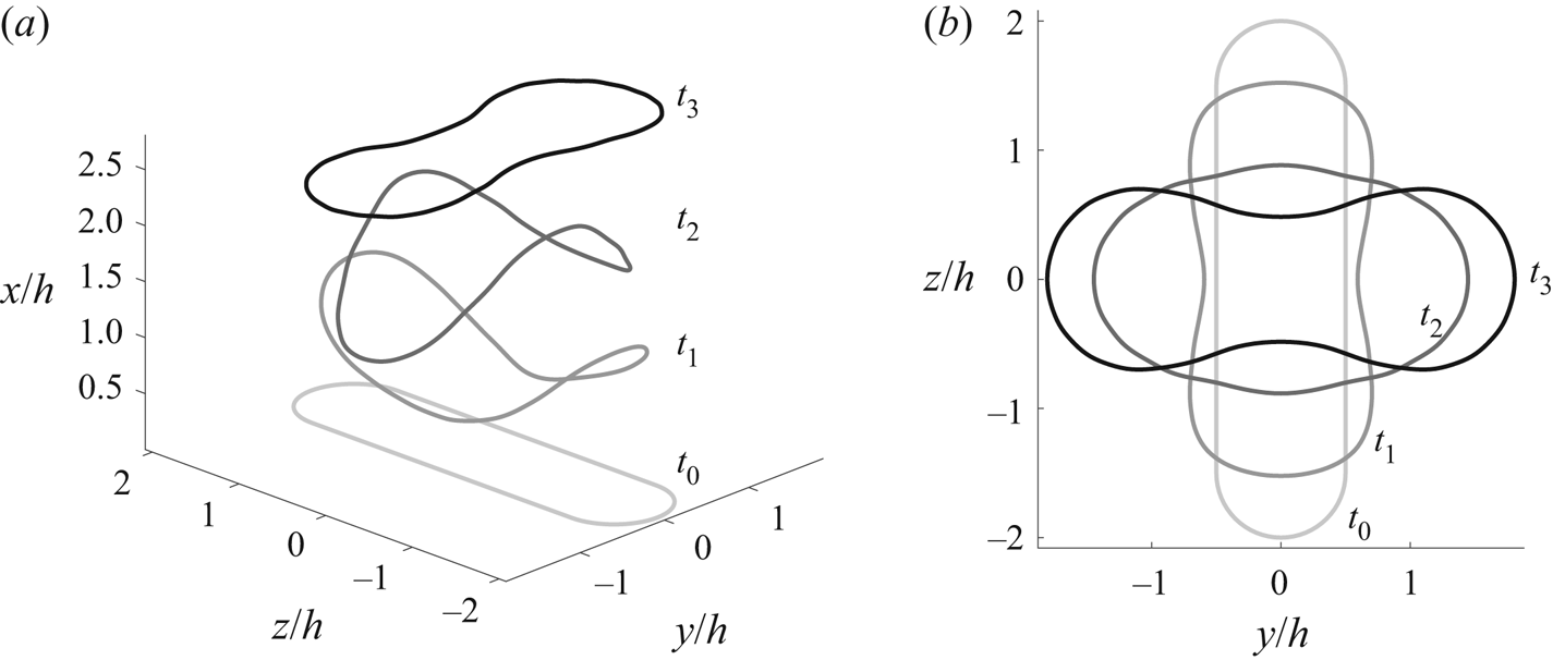
The vortex rings produced by a synthetic jet actuator induce motion both on themselves and in the fluid around them. Arms & Hama (Reference Arms and Hama1965) proved that for an idealized vortex the local self-induction is proportional to the curvature of the vortex filament, and therefore, all non-circular vortex rings ‘wobble’ (i.e. deform) as they travel. For vortex rings with initially symmetric shapes, the three-dimensional (3-D) deformations brought about by variable self-induction lead to a periodic swapping of the vortex ring major and minor axes, a process referred to as axis switching. Axis switching was numerically simulated in different aspect ratio ( $AR$) elliptic vortex rings by Arms & Hama (Reference Arms and Hama1965). Typical results from a simulation of axis switching in an elongated symmetric vortex ring, using a Biot–Savart solver developed by the authors, are presented in figure 1.
Axis switching in an  $AR=4$ vortex ring as modelled numerically using the Biot–Savart relation. Vortex ring axis displayed at four time steps in an
 $(a)$ axonometric projection and
 $(b)$ top view.

Viets & Sforza (Reference Viets and Sforza1972) and Dhanak & Bernardinis (Reference Dhanak and Bernardinis1981) also performed inviscid simulations of non-circular vortex rings but employed a modified Biot–Savart computation to implement a Rankine vortex profile instead of a potential vortex. Each compared the results of their simulations to complementary flow visualization experiments and found remarkable agreement. A common observation of axis switching elliptic vortex rings is that they never truly recover their initial geometry after completing an axis switch (Arms & Hama Reference Arms and Hama1965; Viets & Sforza Reference Viets and Sforza1972; Dhanak & Bernardinis Reference Dhanak and Bernardinis1981). The geometric deviation is almost imperceptible at low  $AR$ values, between one and two, but becomes more pronounced as
 $AR$ increases (Dhanak & Bernardinis Reference Dhanak and Bernardinis1981). The most prominent feature of the deformed ellipse is the narrowing of the vortex ring in the middle of the long axis, giving it a pinched waist (see vortex ring at
 $t_3$ in figure 1b). This pinch gets narrower with increasing
 $AR$ of the vortex ring, and, at some particular
 $AR$, the vortex axes come close enough to each other that the finite width vortex cores overlap. A vortex collision is marked by a viscous interaction which cannot be captured by the inviscid models applied in the studies just discussed and can ultimately lead to the splitting of the vortex ring into smaller sub-rings.
1.2. Vorticity reconnection
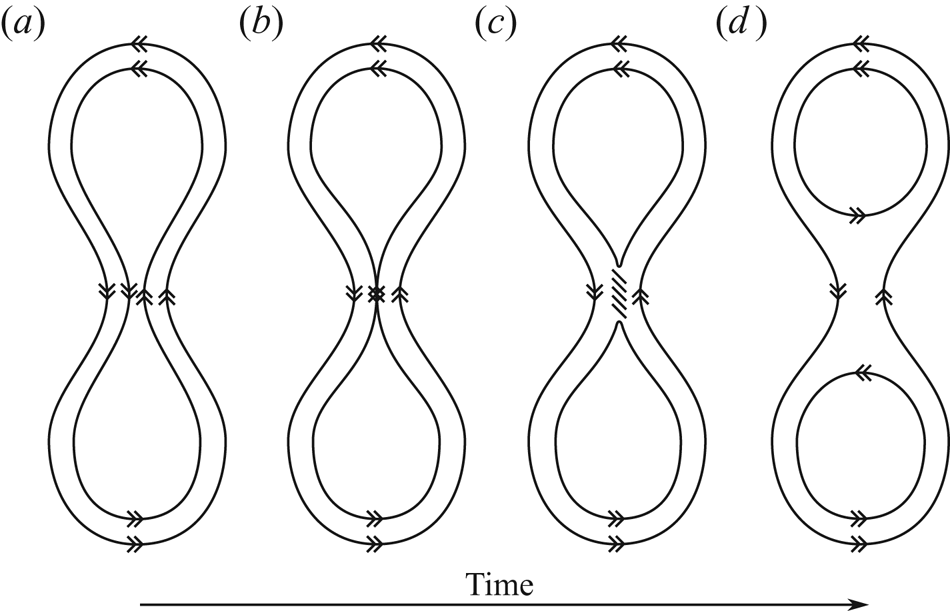
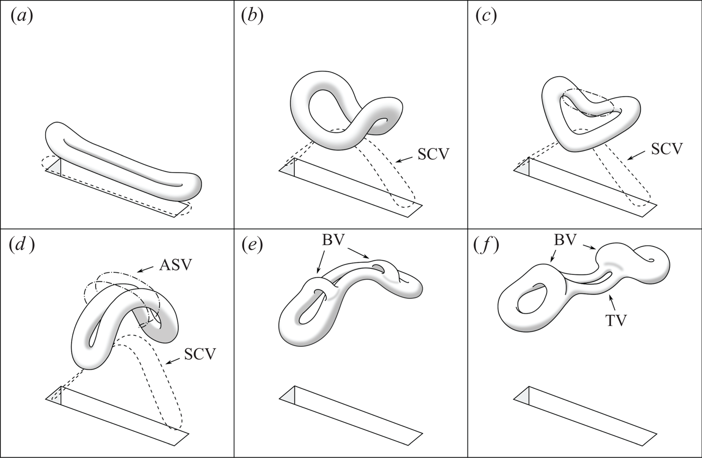
A collision of vortices leads to either augmentation or annihilation of vorticity depending on whether they have parallel or anti-parallel orientation, respectively. When vorticity is not annihilated everywhere in and along the vortices, a process called reconnection or cross-linking can take place. Melander & Hussain (Reference Melander and Hussain1988) thoroughly described the progression and dynamics of vortex reconnection, which they called vortex cut-and-connect. They employed direct numerical simulation to model the collision of two anti-parallel vortex tubes with a sinusoidal perturbation of their axes which locally shifted the initially circular cores of the vortices up and towards each other. This topology was designed to cause the vortices to collide and remain pressed against each other due to self-induction. Their findings revealed that the collision of anti-parallel vortices establishes a contact zone, the cross-section of which is a vortex dipole. As contact continues, the cores of the vortex dipole are deformed, developing wider ‘heads’ on the downstream side and narrow streamwise-elongated ‘tails’ on the upstream side, referred to as a head–tail structure (Kida, Takaoka & Hussain Reference Kida, Takaoka and Hussain1991b). A sketch of how vortex lines within an axis switching vortex ring are affected by a collision is provided in figure 2, while the impact on the vortex tube topology is presented in figure 3. In the contact zone, the anti-parallel vortex lines from the two vortices collide and are locally annihilated by viscous cross diffusion (figure 2b). The unannihilated part of the vortex line in one vortex connects or cross-links with the corresponding vortex line in the other vortex at the edge of the contact zone, forming a cusp (figure 2c). The vortex line cross-linking and cusp formation occurs on both sides of the contact zone.
Vorticity reconnection in a vortex core collision of an axis switching vortex ring. The closed curves represent two vortex lines in a vortex ring core with the direction of vorticity denoted by a double arrow ( $\gg$).

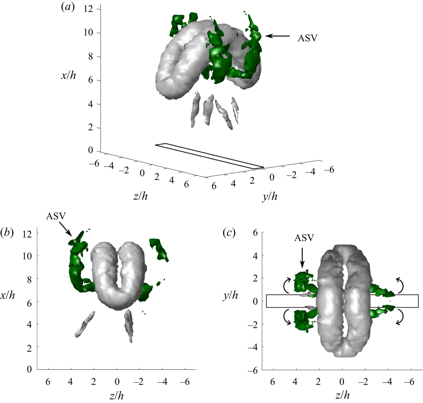
Sketch of an elongated vortex ring undergoing axis switching (a–e), vorticity reconnection (d,e) and bifurcation (f). The dashed line (a–d) represents a vortex line in the shear layer which becomes the streamwise corner vortices (SCV), the dash-dotted line (c,d) represents a vortex line that becomes the arc-shaped vortices (ASV); both are discussed in § 4.

The cross-linking interaction is by necessity viscous because vortex lines lose their material identity during the process (Ashurst & Meiron Reference Ashurst and Meiron1987; Kida & Takaoka Reference Kida and Takaoka1987; Melander & Hussain Reference Melander and Hussain1988). However, circulation is not lost due to this viscous phenomenon because, while vorticity is being annihilated in the contact zone, cross-linking generates realigned vorticity of equivalent circulation in the orthogonal plane (Melander & Hussain Reference Melander and Hussain1988). This may be viewed as something akin to spatial conservation of circulation within the aggregate vortex system.
Once cross-linked, the reconnected vortex lines are advected upwards by the upwash between the vortex dipole and are deposited above the vortex pair at the point of highest stretching rate (Kida, Takaoka & Hussain Reference Kida, Takaoka and Hussain1991a). Viscous diffusion at the narrow cusp formed by the reconnection rounds out the vortex line, and the high curvature in the resulting hairpin shape causes the vortex line to recede from the contact zone due to self-induction (figure 2d). In reality, the sketch of vorticity reconnection in figure 2 is highly simplified because the cross-linked and uncut vortex lines are also rotating around the vortex core, which causes them to become twisted (Kida et al. Reference Kida, Takaoka and Hussain1991a).
As the cores of the colliding vortices continue to rotate, new vortex lines are fed into the bottom of the contact zone and are also cross-linked. The accumulation of these reconnected vortex lines forms two ‘bridge’ vortices on either side of the contact zone (denoted ‘BV’ in figure 3e). The growing bridge vortices induce a strengthening downwash in the contact zone which eventually overpowers the upward self-induction of the colliding dipole. This forces the original vortex tubes downwards, reversing their curvature such that self-induction drives the pair apart now instead of pushing them together (figure 3f). After this point, the rate of vorticity annihilation is dramatically reduced. What is left of the post-collision dipole is a weak vortex pair referred to as ‘threads’ (denoted ‘TV’ in figure 3f). Threads exist because the bridge vortices stop the vorticity reconnection process before all of the vorticity can be cut and cross-linked. In the topology studied by Melander & Hussain (Reference Melander and Hussain1988), which was specifically designed to force the vortices to collide and remain pressed against one another, approximately 20 %–30 % of the original vortex circulation remained in the threads around the time that vorticity reconnection effectively ceased. The detection of thread vortices is common in similar studies.
The experiments of Fohl & Turner (Reference Fohl and Turner1975) and Oshima & Asaka (Reference Oshima and Asaka1977) revealed that vorticity reconnection can also cause colliding circular vortex rings to merge into a single elongated vortex ring. This distorted ring switches axes and comes in contact with itself along the minor axis, splitting back into two vortex rings in a second reconnection event. Kida et al. (Reference Kida, Takaoka and Hussain1991a) simulated this interaction numerically. The first reconnection event was rapid, and over 70 % of the circulation was redistributed by cross-linking because the vortices in the contact zone were firmly forced together by induction from the outboard regions of the vortex rings. By comparison, the second reconnection event was less intense because the vortices were forced against each other by the relatively weaker local self-induction and only approximately 50 % of the circulation was transferred through cross-linking. Once re-separated, the vortex rings propagated away from the axis of the collision on diverging paths that lay in a plane orthogonal to the one that the original vortex rings had converged on.
1.3. Vortex ring bifurcation
Vortex ring bifurcation has been studied more directly by generating single elliptic or elongated vortex rings of sufficiently high  $AR$ such that their cores collide just prior to completion of their first axis switch. Kambe & Takao (Reference Kambe and Takao1971) and Dhanak & Bernardinis (Reference Dhanak and Bernardinis1981) captured the bifurcation of vortex rings from rectangular and elliptic orifices, respectively, in their flow visualization experiments. The
 $AR=2.5$ elliptic vortex ring tested by Dhanak & Bernardinis (Reference Dhanak and Bernardinis1981) developed a pinch in the ring's shape at the first axis switch but did not bifurcate like the vortex ring in the
 $AR=5$ case. This led the authors to conclude that the critical
 $AR$ above which bifurcation occurs must lie in the range
 $AR=2.5\text {--}5$.
Oshima et al. (Reference Oshima, Izutsu, Oshima and Hussain1988) conducted an experimental study of vortex rings from  $AR=2, 3$ and
 $4$ elliptic orifices using schlieren visualization and x-wire probe thermal anemometry measurements. The velocity field data from the x-wire measurements enabled circulation to be computed on the two orthogonal centreline planes. The redistribution of vorticity due to the cross-linking was detected for all three orifices, although as
 $AR$ increased, so did the percentage of circulation which was reconnected. They reported that for the
 $AR=2$ case, the vortex ring did not bifurcate, while they labelled the
 $AR=3$ and
 $4$ cases as ‘partial bifurcations’. Cheng, Lou & Lim (Reference Cheng, Lou and Lim2016) also used the term ‘partial bifurcation’ to describe the cases they simulated in which vorticity reconnection occurred, but two smaller vortex rings with unique trajectories were not formed. We choose instead to label this as ‘vorticity reconnection without bifurcation’ and reserve the term ‘bifurcation’ for when a sufficient fraction of vorticity has been cut and cross-linked to produce two independent vortex rings. Bifurcation is distinguishable from vorticity reconnection without bifurcation because the colliding portion of the original vortex ring does not spread out away from the contact zone to form a new major axis downstream. In other words, axis switching terminates when bifurcation has occurred under our definition. Hussain & Husain (Reference Hussain and Husain1989) similarly viewed continued axis switching of the vortex ring as incompatible with bifurcation.
More recently, a number of groups have employed higher fidelity numerical methods to simulate bifurcation in elongated vortex rings for a range of initial  $AR$ values (Kiya & Ishii Reference Kiya and Ishii1991; Kiya et al. Reference Kiya, Toyoda, Ishii, Kitamura and Ohe1992; Grinstein Reference Grinstein1995; Zhao & Shi Reference Zhao and Shi1997; Cheng et al. Reference Cheng, Lou and Lim2016). All found that, below some critical
 $AR$, elongated vortex rings did not bifurcate, but above that limit, the vortex ring split into two or more rings. Grinstein (Reference Grinstein1995) and Cheng et al. (Reference Cheng, Lou and Lim2016) predicted that after bifurcation the two smaller vortex rings would then turn in towards each other due to mutual induction and would subsequently collide and recombine. However, this behaviour was not reported to have occurred in the flow visualization experiments by Kambe & Takao (Reference Kambe and Takao1971), Dhanak & Bernardinis (Reference Dhanak and Bernardinis1981) or Kiya et al. (Reference Kiya, Toyoda, Ishii, Kitamura and Ohe1992). A survey of the various simulations and experiments discussed reveals that the critical
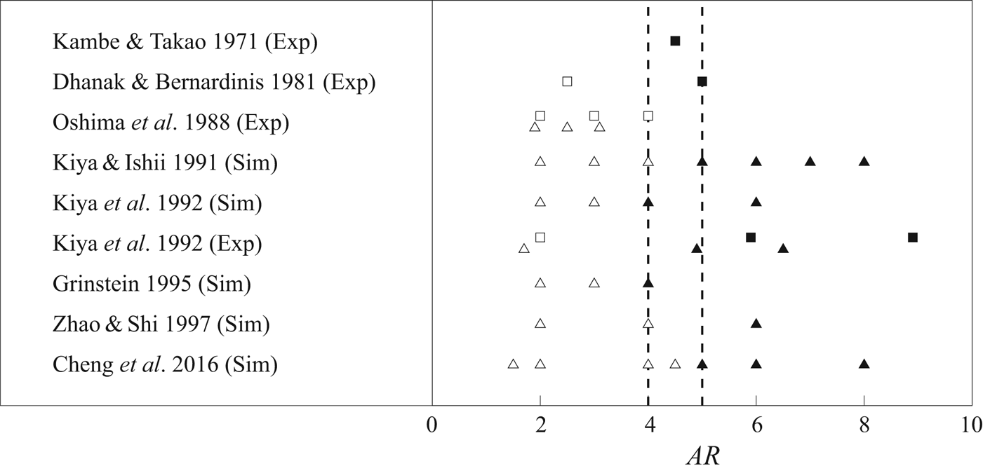
 $AR$ for bifurcation ranges from 4 to 5 for elliptic or pseudo-elliptic vortex rings (i.e. elongated vortex rings with curved ends and rectilinear midsections) (figure 4). Some factors which may contribute to the variability in the predicted critical
 $AR$ include how
 $AR$ was reported, the precise shape of the vortex ring, the thickness of the vortex core and the vortex ring Reynolds number (Cheng et al. Reference Cheng, Lou and Lim2016).
A survey of simulations (Sim) and experiments (Exp) showing at what orifice  $AR$ (
 $\square$) or vortex ring
 $AR$ (
 $\triangle$) the elongated vortex rings bifurcated (filled symbols) or did not bifurcate (hollow symbols). Vertical dashed lines indicate the proposed range of the critical AR for bifurcation.

Axis switching and vortex ring bifurcation are not phenomena limited to isolated vortex rings in quiescent fluid. They have also been observed in jets. The continuous shear layer enveloping a steady jet is prone to instability, resulting in vortex ring formation over a range of axial distance from the orifice. Exciting the jet at an appropriate frequency leads to earlier roll-up of vortex rings at an essentially fixed location (Hussain & Husain Reference Hussain and Husain1989). In non-circular jets, the vortex rings undergo axis switching which enhances the jet's entrainment relative to circular and plane jets (Ho & Gutmark Reference Ho and Gutmark1987; Husain & Hussain Reference Husain and Hussain1993). The enhanced entrainment associated with axis switching has motived the study of various non-circular nozzle geometries, including elliptic (Ho & Gutmark Reference Ho and Gutmark1987), triangular (Gutmark et al. Reference Gutmark, Schadow, Parr, Hanson-Parr and Wilson1989) and square jets (Grinstein & DeVore Reference Grinstein and DeVore1996). Hussain & Husain (Reference Hussain and Husain1989) not only detected axis switching in elliptic jets, but when high-amplitude excitation at the preferred mode frequency was imposed on the  $AR=4$ jet, they observed vortex ring bifurcation at the point of the first axis switch. Conversely, the vortex rings in the
 $AR=2$ elliptic jet did not bifurcate which suggests the critical
 $AR$ for vortex ring bifurcation in jets may be similar to the limit for isolated vortex rings.
1.4. Vortex dynamics in synthetic jets
The dynamics in a synthetic jet differs from that in both isolated vortex rings and continuous jets. Unlike an isolated vortex ring, the vortex rings in a synthetic jet are subject to mutual induction from the other vortex rings in the train. In addition, synthetic jet vortices do not propagate into quiescent fluid; instead they encounter shed vorticity from older vortices as well as a gradually developing steady velocity component from diffused momentum. Unlike a continuous jet, the momentum in a synthetic jet decreases in the downstream direction due to the adverse pressure gradient generated by the suction phase of the actuator (Smith & Glezer Reference Smith and Glezer1998). The dynamics of a forming synthetic jet also leads to much higher initial entrainment than an equivalent continuous jet (Smith & Glezer Reference Smith and Glezer1998). These features give synthetic jets a unique character and are important factors influencing the vortex ring dynamics in the jet.
Although fundamental analysis of coherent structures in synthetic jets is not a common focus of research on the actuators, with most concentrating on practical application, several noteworthy studies on synthetic jets in quiescent conditions have contributed to our understanding of the associated vortex dynamics. The vorticity contour plots computed from particle image velocimetry (PIV) data by Amitay & Cannelle (Reference Amitay and Cannelle2006) on the two centreline symmetry planes of their actuator's rectangular orifices ( $AR=50.8,\ 76.2$ and
 $101.6$) reveal signs of vortex ring axis switching in a synthetic jet. Specifically, the initial minor axis of the jet grew rapidly while the initial major axis shrank in width in a pattern similar to isolated elliptic vortex rings. Amitay & Cannelle (Reference Amitay and Cannelle2006) also observed multiple types of secondary structures in their synthetic jet including cross-stream structures inside the vortex ring and, potentially, streamwise structures trailing behind it.
Van Buren, Whalen & Amitay (Reference Van Buren, Whalen and Amitay2014a) obtained stereoscopic particle image velocimetry (SPIV) data on multiple parallel planes in  $AR=6,\ 12$ and
 $18$ rectangular orifice synthetic jets to investigate the evolution of flow structures in the jets. The multi-planar SPIV data enabled the 3-D reconstruction of vortex ring axis shape at different actuator phases. These reconstructions revealed vortex ring axis switching deformations very similar to those predicted in simulations of isolated vortex rings. At the higher
 $AR$ values, Van Buren et al. (Reference Van Buren, Whalen and Amitay2014a) also observed secondary structures forming inside the jet. Interestingly, the authors did not report the occurrence of vortex ring bifurcation despite capturing pinching in the vortex ring shape at the first axis switch and testing orifices at or above the critical
 $AR$.
Vortex ring bifurcation has not been a topic of extensive study in synthetic jets; however, it has been observed in a small number of studies. Menon & Soo (Reference Menon and Soo2004) predicted that the vortex rings in an  $AR=25$ rectangular orifice synthetic jet would trifurcate upon formation in their large-eddy lattice Boltzmann method simulations. This type of reconnection event, while the vortex ring was still in its original orientation, is consistent with the pattern IV predicted by Kiya & Ishii (Reference Kiya and Ishii1991) for an isolated vortex ring. Van Buren et al. (Reference Van Buren, Beyar, Leong and Amitay2016) and Lindstrom, Monastero & Amitay (Reference Lindstrom, Monastero and Amitay2018) in SPIV experiments and Belanger, Zingg & Lavoie (Reference Belanger, Zingg and Lavoie2020) in a large-eddy simulation reported potential bifurcations of the vortex rings from moderate
 $AR$ rectangular orifice synthetic jets in a cross-flow. However, the bifurcation of a vortex ring while interacting with a cross-flow boundary layer develops differently than a natural bifurcation due only to self-induced vortex deformations.
Vortex ring bifurcation in synthetic jets was not unambiguously established in a quiescent experiment until recently. Wang et al. (Reference Wang, Feng, Wang and Li2018a) obtained high-speed PIV data for a synthetic jet in water on the two centreline symmetry planes and SPIV data on several cross-sectional planes of the jet. Without multi-planar or tomographic PIV, the authors were unable to perform a true 3-D reconstruction of the flow field; however, they did apply Taylor's frozen-flow hypothesis to construct an approximation of the vortex structure from the SPIV data taken in four cross-sectional planes. These approximate vortex representations enabled qualitative observations including the presence of vortex ring bifurcation around the first axis switch of the  $AR=5$ rectangular orifice and the lack of bifurcation of the
 $AR=4$ orifice jet. A visualization of the
 $AR=3$ orifice synthetic jet revealed two types of secondary structures near the vortex ring. The first was a counter-rotating pair of parallel vortices downstream of the deforming vortex ring that arc back around the primary structure in a bow wave-like shape which Wang et al. (Reference Wang, Feng, Wang and Li2018a) refer to as ‘arc-like vortices’. The other type was a set of two counter-rotating pairs of ‘streamwise vortices’ trailing behind the vortex ring. The presence of these secondary structures along with the vortex ring bifurcation in the
 $AR=5$ orifice jet was confirmed in a complementary flow visualization study by Wang et al. (Reference Wang, Feng, Wang and Li2018b).
This review of the literature reveals that vortex ring bifurcation has been well studied in isolated vortex rings, but that there has been much less work done investigating the same phenomena in synthetic jets. In general, many fundamental questions remain unanswered about the vortex dynamics in synthetic jets, including the types and topologies of secondary structures formed and the mechanisms behind their generation. The dynamics of coherent structures in jets has important implications for entrainment rate, momentum distribution and the shape of the jet (Hussain & Husain Reference Hussain and Husain1989). These characteristics are of keen interest to the flow control, heat transfer and reacting flows communities.
In the interest of expanding our understanding of vortex dynamics in synthetic jets, an experiment was designed with the following goals. The first goal was to confirm the presence and the structure of vortex ring bifurcation in an  $AR=13$ rectangular orifice synthetic jet using multi-planar, SPIV-based 3-D reconstructions of the periodic structures in the jet. The second was to establish how vortex ring bifurcation affects key characteristics of synthetic jets, including the shape, momentum and entrainment rate. The 3-D jet reconstruction also served the goals of establishing the types of secondary structures formed in a moderate
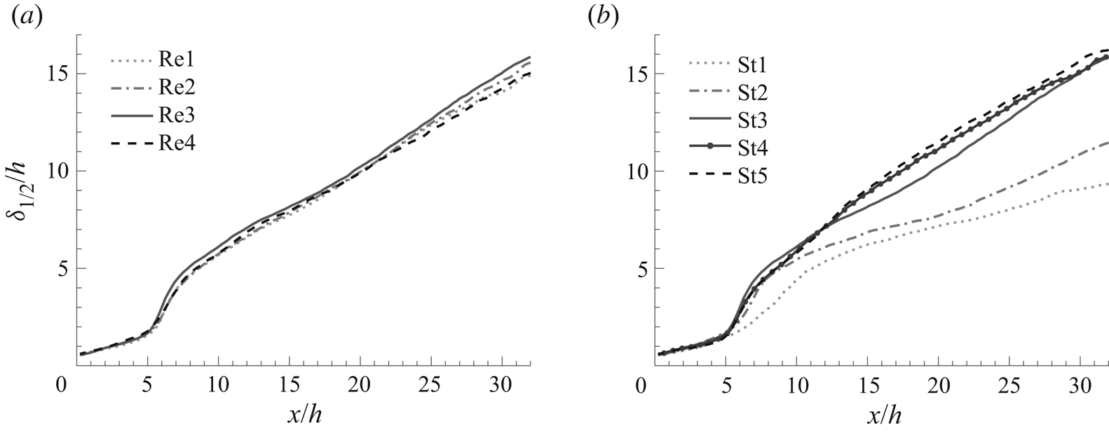
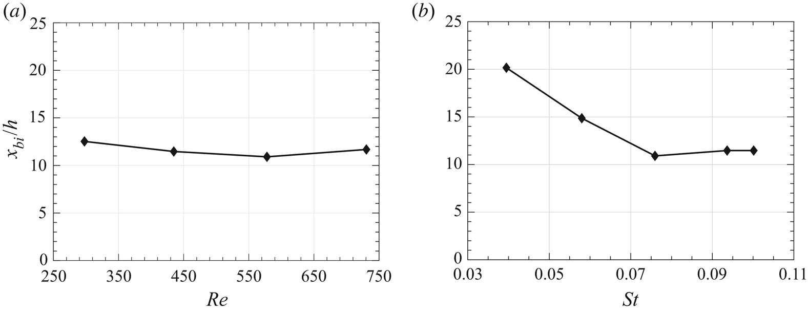
 $AR$ synthetic jet and how those structures evolved with the primary vortex ring. Next, the study sought to determine under what conditions vortex ring bifurcation occurs in synthetic jets. To this end, the Reynolds number and Strouhal number of the jet were varied independently between 298 to 731 and 0.039 to 0.100, respectively. Finally, the cases with different Strouhal numbers were also tested to understand how multi-vortex mutual interactions influence vorticity reconnection in bifurcating vortex rings. Accordingly, the experimental apparatus and techniques used to achieve these goals are described in § 2. The first two goals are addressed in § 3 which presents a 3-D reconstruction of the vortex rings at one operating condition of the jet and explores the features of bifurcation. Section 4 focuses on the secondary structures in the synthetic jet. Next, § 5 investigates how the operating conditions of the jet influence the bifurcation process. Finally, the findings of this study are summarized, and other synthetic jet studies are discussed in light of these findings.
2. Experimental methods
To study the vortex dynamics of synthetic jets in quiescent conditions, a synthetic jet actuator (SJA) was designed and built in-house. The external flow field produced in air by this actuator was measured using SPIV on the centreline symmetry planes for all conditions tested. In addition, multiple parallel planes were collected throughout the flow field for one test condition, enabling a 3-D reconstruction of the jet.
2.1. The actuator
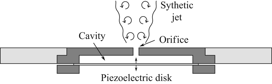
The SJA used in this study has a circular cylindrical cavity with a 63.5 mm diameter bi-morph, piezoelectric, bending disk driver positioned opposite the orifice which is contained in a stereolithography (SLA) printed part (figure 5). The SLA orifice part also contains the side and upper wall of the  $58.4\pm 0.2\ \textrm {mm}$ diameter,
 $3.2\pm 0.2\ \textrm {mm}$ tall cavity and was printed in-house with a Formlabs Form 2 3-D printer. A set of precision metric pins and callipers were used to measure the dimensions of the rectangular orifice which was found to be
 $14.59\pm 0.05\ \textrm {mm}$ long (
 $l$) by
 $1.10\pm 0.01\ \textrm {mm}$ wide (
 $h$) yielding an aspect ratio,
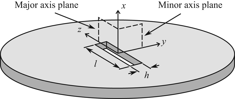
 $AR=l/h$, of 13 (figure 6). Additionally, the orifice was designed with a
 $2.59\pm 0.2\ \textrm {mm}$ deep throat which is roughly 2.35 times longer than the orifice is wide. The coordinate system used in this study aligns the
 $x$-direction with the axis of the jet, the
 $y$-direction with the short or minor axis of the orifice and the
 $z$-direction with the long or major axis of the orifice. The
 $x$,
 $y$ and
 $z$-directions will also be referred to as the axial or streamwise, cross-stream and spanwise directions, respectively.
Cross-section of a typical synthetic jet actuator.

Schematic of the data coordinate system and orifice dimensions.

The velocity at the throat of a SJA varies with time and has a zero mean. Therefore, a characteristic velocity of the jet was obtained by integrating the jet velocity at the exit of the orifice,  $u_o(t)$, over the blowing part of the cycle before averaging over the full cycle period, T (Smith & Glezer Reference Smith and Glezer1998). The result is called the average blowing velocity,
 $U_o$, and is related to the effective stroke length,
 $L_o$, and the actuation frequency,
 $f$, in (2.1).
 \begin{equation} U_o = \frac{1}{T} \int_{0}^{T/2} u_o (t)\,\textrm{d}t = f\, L_o. \end{equation}
The two common orifice length scales used in related studies are the orifice width,  $h$, and the equivalent diameter,
 $D_{eq}$, which is the diameter of a circular orifice with the same exit area. In order to be consistent with prior work on rectangular orifice synthetic jets, the orifice width,
 $h$, is used here. The one exception is stroke length,
 $L_o$, which has been non-dimensionalized by
 $D_{eq}$ to facilitate comparison with the vortex formation number set out by Gharib, Rambod & Shariff (Reference Gharib, Rambod and Shariff1998). The definitions for Reynolds number (
 $Re$) and Strouhal number (
 $St$) that were employed are presented in (2.2) and (2.3), respectively:
 \begin{gather} Re = \frac{U_o h}{\nu}, \end{gather}
 \begin{gather} St = \frac{f\,h}{U_o}. \end{gather}
This Strouhal number is effectively the ratio of the actuation frequency to the convective frequency and provides important information about the spacing of coherent structures in the jet and whether a jet is even formed (Holman et al. Reference Holman, Utturkar, Mittal, Smith and Cattafesta2005). Note that non-dimensional stroke length,  $L_o/D_{eq}$, is merely the reciprocal of the
 $St$ when both are computed using the length scale
 $D_{eq}$.
During operation the actuator was driven by a sinusoidal voltage waveform from an Agilent 33500B function generator which was boosted by a Piezo Masters VP7210 amplifier. The conditions of the jet were controlled by varying the driving signal produced by the waveform generator. Adjusting the frequency of the driving signal directly modified the actuator frequency, while varying the voltage amplitude to the piezoelectric disk altered the actuator stroke length, and therefore the average blowing velocity.
The performance of the actuator was mapped for a range of driving voltages and frequencies using an AA Labs System AN-1003 constant-temperature anemometer system with a Dantec Dynamics  $5\ \mathrm {\mu }\mathrm {m}$ miniature straight single element hot-wire probe (Model Number 55P11) positioned at the middle of the orifice with the wire aligned to the major axis and inserted to half the depth of the throat. Peak resonance of the actuator was found to occur at a driving frequency,
 $f$, of 470 Hz and produced a jet with a peak blowing velocity,
 $U_p$, of up to
 $50\ \textrm {m}\,\mathrm {s}^{-1}$. The average blowing speed,
 $U_o$, of the jet was determined by integrating the blowing phase of the rectified hot-wire data for at least 140 actuation cycles and dividing by the number of cycles. This integration was conducted because, at some operating conditions, the velocity programme,
 $u_o(t)$, at the jet orifice was slightly broader than a pure sinusoid. As a result, the use of an idealized sinusoidal relationship,
 $U_o = U_p/{\rm \pi}$, resulted in non-negligible errors in
 $U_o$.
2.2. SPIV set-up and data processing
The SPIV experiments were conducted with the actuator inside a  $76\ \textrm {cm} \times 61\ \textrm {cm} \times 61\ \textrm {cm}$ quiescent enclosure with cast acrylic panels on four sides of the box and a door on the fifth side to isolate the experiment from air currents in the room while still allowing optical access. Inside the enclosure the actuator was mounted on a two-axis linear motorized traverse system in an
 $y$–
 $z$ configuration that facilitated the precise positioning of the actuator and enabled the jet to be stepped through the laser for multi-planar SPIV measurements. The air was seeded for the SPIV measurements by burning incense inside the enclosure prior to data acquisition. The median diameter of incense smoke particles has been reported to fall between 0.1 and
 $1 \ \mathrm {\mu }\textrm {m}$ (Chang, Lee & Tseng Reference Chang, Lee and Tseng2007).
A LaVision SPIV system comprising two  $2560 \times 2160$ pixel resolution 16-bit dynamic range sCMOS cameras was used to image the flow field. Both cameras were mounted with Nikon Micro-NIKKOR 200 mm
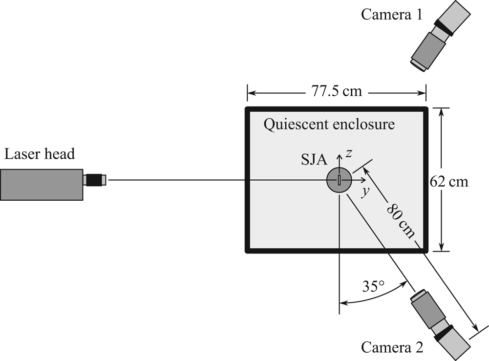
 $f/4D$ macro lenses with Scheimpflug adapters that allowed the full imaging plane to be brought into sharp focus even though the camera sensor was not parallel to the plane. The cameras were set up on opposite sides of the laser beam in a forward scattering orientation at an angle of
 $35^{\circ }$ relative to the normal of the measurement plane (figure 7). This arrangement enabled the cameras to capture out of plane particle motion so that the three-component velocity field could be measured. The distance between the synthetic jet orifice and the camera sensors was approximately 80 cm which produced a
 $31.8\ \textrm {mm} \times 37.6\ \textrm {mm}$ field of view and a magnification of
 $14.7\ \mathrm {\mu }\textrm {m}\,\textrm {pixel}^{-1}$. Illumination was provided by a Quantel Evergreen dual-pulsed 200 mJ Nd:YAG laser fitted with a focusing element and a
 $-50\ \textrm {mm}$ focal length cylindrical lens which spread the laser into a vertical sheet. The laser light sheet was focused to a minimum waist above the actuator orifice. The SPIV data were acquired with the laser light sheet parallel with either the
 $x\text {--}z$ plane which contains the orifice major axis, or the
 $x\text {--}y$ plane which contains the orifice minor axis (figure 6). The orifice centreline planes, i.e. the
 $x\text {--}z$ plane and
 $x\text {--}y$ plane, are referred to as the major axis plane and the minor axis plane, respectively. Note, this orifice-relative terminology will be used irrespective of the orientation of the vortex ring axes for all forthcoming discussions.
Experimental configuration for SPIV measurements.

To reconstruct the 3-D, three-component velocity field, SPIV data were acquired in one half of the jet on a set of tightly spaced, parallel measurement planes by stepping the jet through the laser light sheet using the two motorized linear traverses. Three to four more sparsely distributed data planes were also acquired in the other half of the jet and compared with their counterpart planes on the opposite side of centreline to confirm symmetry of the periodic structures. The level of symmetry observed in the off-centreline planes is similar to the left–right symmetry in the two centreline planes, the velocity and vorticity fields of which are presented in § 3. Thus the full jet was reconstructed by mirroring the tightly spaced planes onto the opposite side of centreline. This type of multi-planar reconstruction was conducted twice: once with the measurement plane parallel with the minor axis plane and again with the measurement aligned with the major axis plane. The two independent reconstructions not only aided in checking the symmetry of the coherent structures but also made it possible to confirm that the orientation of the measurement plane relative to the vortices did not affect whether a vortex could be resolved or not. Because no substantial differences were seen in the structures detected in the two reconstructions, only the reconstruction with the measurement plane parallel with the major axis plane is presented in this paper. That reconstruction is composed of 22 measurement planes (43 after mirroring) which are distributed every 0.5 mm in the  $y$-direction.
A programmable timing unit (PTU) controlled and synchronized the release of the camera shutters and the firing of the lasers in short two-image bursts. The time between the two images captured by the cameras varied from  $8\ \mathrm {\mu }\mathrm {s}$ to
 $15\ \mathrm {\mu }\mathrm {s}$ depending on the speed of the jet for the given test condition. The three-component velocity field was computed in the measurement plane using the DaVis 8.4.0 software from LaVision to find the stereoscopic cross-correlation between the two successive image pairs obtained from the two cameras. Processing was completed in three passes with a single pass utilizing
 $64 \times 64$ pixel interrogation windows followed by two passes with
 $32 \times 32$ pixel interrogations windows. All passes used a 50 % interrogation window overlap, and the result after masking and processing was a
 $154 \times 153$ vector field with a resolution of 4.25 vectors
 $\mathrm {mm}^{-1}$.
The uncertainties in the  $u$,
 $v$ and
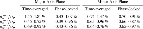
 $w$ velocity component measurements were also computed using the correlation statistics method in DaVis 8.4.0 (Wieneke Reference Wieneke2015). For consistency with the uncertainty reporting convention used by Wieneke (Reference Wieneke2015), the root-mean-square of the uncertainty across the velocity field for all vectors inside the jet (i.e. in the region where
 $u(x,y) > 0.01*u_{max}(x)$) was computed. This yielded a single root-mean-square-averaged uncertainty of each velocity component in a given ensemble averaged phase-locked or time-averaged measurement. The uncertainty values at all jet conditions and actuator phases measured are reported as ranges in table 1. The uncertainty in velocity was also propagated to derived quantities, like circulation and volume flux, assuming normally distributed error (Sciacchitano et al. Reference Sciacchitano, Neal, Smith, Warner, Vlachos, Wieneke and Scarano2015) using the method outlined by Sciacchitano & Wieneke (Reference Sciacchitano and Wieneke2016). The propagated uncertainty in circulation is indicated on the relevant plots with uncertainty bars. However, the uncertainty in volume flux was too small for the uncertainty bands to be easily distinguished from the data in the figures and so the uncertainty bands have been omitted. For reference, the fractional uncertainty in the volume flux of the full jet ranged from
 $\sigma _Q/Q = 0.08\,\%\text { to }1.83\,\%$.
Uncertainty in centreline plane SPIV measurements.

Both time-averaged and phase-locked SPIV data were obtained in this experiment. For time-averaged measurements, 500 image sets were captured throughout the cycle of the actuator, and the average of the vector fields computed from them provided the mean jet characteristics. These measurements were taken by setting the PTU to trigger the SPIV system at a frequency which was not a factor of the actuator frequency to progressively alias the signal. Alternatively, for phase-locked measurements, 400 image sets were taken on the centreline planes, or 200 images sets on the off-centreline planes, at a single phase angle of the jet driving frequency for multiple actuation cycles. Ensemble averaging the vector fields computed from these image sets reveals the periodic structures at that point in the actuation cycle. Phase-locking was achieved by setting the PTU to trigger off a specific point of the voltage waveform from the function generator. Three phases of the actuator, evenly spaced across the cycle, were obtained on each measurement plane for each jet operating condition. The precise set of phase angles used varied for the different jet operating conditions in order to capture the vortex rings at similar points in the bifurcation process.
The phase lag between the driving signal output from the function generator and the fluid dynamic response of the jet was quantified by comparing the transient data from the hot-wire probe inserted into the actuator orifice to the unamplified driving signal. Accordingly, the phase angles,  $\phi$, quoted in this paper are corrected to represent the phase of the jet inside the orifice. Therefore, the values of
 $\phi$ can be approximately interpreted as
 $\phi =0^{\circ }$ representing the start of the blowing cycle,
 $\phi =90^{\circ }$ the point of peak blowing,
 $\phi =180^{\circ }$ the start of the suction phase, and
 $\phi =270^{\circ }$ the point of peak suction.
Two techniques were used to identify vortices in the SPIV data. In post-processing planar SPIV data the  $\mathcal {Q}$-criterion was utilized for vortex identification, where
 $\mathcal {Q}$ is the second invariant of the velocity gradient tensor. In this technique, vortices are identified as regions of the flow where the magnitude of rotation exceeds the magnitude of strain, which distinguishes the vorticity in the core of a vortex from the vorticity generated by the shear in a boundary layer, for example (Hunt, Wray & Moin Reference Hunt, Wray and Moin1988; Jeong & Hussain Reference Jeong and Hussain1995). Another virtue of the
 $\mathcal {Q}$-criterion is that it is Galilean invariant. The equation for
 $\mathcal {Q}$ is
 \begin{equation} \mathcal{Q} = \tfrac{1}{2}\left(u^2_{i,i}-u_{i,j}u_{j,i}\right)=-\tfrac{1}{2}u_{i,j}u_{j,i}=\tfrac{1}{2}\left(\left\|\boldsymbol{\varOmega}\right\|^2-\|\boldsymbol{\mathsf{S}}\|^2\right), \end{equation}
where  $\|\boldsymbol {\varOmega }\|$ and
 $\|\boldsymbol{\mathsf{S}}\|$ in (2.4) are the Frobenius norms of the rotation rate and strain rate tensors, respectively. For vortex detection, a threshold was applied to the
 $\mathcal {Q}$ field which was either a percentage of the maximum
 $\mathcal {Q}$ in the field or a fixed value greater than zero. To identify the location of the vortex axis, the point of maximum vorticity was interpolated from the SPIV grid data in the region selected by the
 $\mathcal {Q}$-criterion.
The swirling strength criterion was used to visualize the vortices in the 3-D reconstructed jet. This technique examines the magnitude of the imaginary part of the velocity gradient tensor eigenvalues, denoted  $\lambda _{ci}$ in (2.5) (Zhou et al. Reference Zhou, Adrian, Balachandar and Kendall1999).
 \begin{equation} \boldsymbol{\nabla} \boldsymbol{u} = [\boldsymbol{\nu_r} \enspace \boldsymbol{\nu_{cr}} \enspace \boldsymbol{\nu_{ci}}]\begin{bmatrix} \lambda_r & 0 & 0\\ 0 & \lambda_{cr} & \lambda_{ci}\\ 0 & -\lambda_{ci} & \lambda_{cr}\end{bmatrix}[\boldsymbol{\nu_r} \enspace \boldsymbol{\nu_{cr}} \enspace \boldsymbol{\nu_{ci}}]^{\textrm{T}}. \end{equation}
When the eigenvalues of the velocity gradient tensor include a complex conjugate pair, then  $\lambda _{ci}$ is non-zero and swirling motions are present in the flow. Setting a threshold greater than zero on
 $\lambda _{ci}$ selects only regions of the flow where the strength of the swirling motion is higher than the threshold. The swirling strength criterion is also Galilean invariant and was found to be slightly more capable than the
 $\mathcal {Q}$-criterion at detecting weak secondary structures without also accentuating noise in the experimental data.
Isosurfaces of phase-locked  $\lambda _{ci}$ and
 $|\boldsymbol {\omega }|$ are presented in several figures in §§ 3 and 4 to demonstrate the 3-D shape of the deforming vortex rings. The isosurfaces are plotted at a level which is a percentage of either the maximum value of the quantity throughout the whole flow field or the maximum observed within a particular generation of the vortex ring, i.e. the local maximum. Different isosurfaces levels were experimented with to determine which values most effectively highlight the flow features to be discussed. For example, isosurfaces at 20 %–50 %
 $\lambda _{ci,max}$ delineated the most recently formed vortex in its entirety, 5 %–20 %
 $\lambda _{ci,max}$ captured two generations of vortex rings and values of 3 %–4 %
 $\lambda _{ci,max}$ were effective in visualizing secondary structures.
Identifying vortex locations in instantaneous PIV measurement fields – as opposed to the average field of a phase-locked measurement – is challenging due to measurement noise and turbulence, which is why it is usually not attempted. However, notable success was achieved in this study by computing the derivatives of velocity needed to find  $\mathcal {Q}$ using a spatially filtered differentiation technique. This technique utilizes a circular stencil with a diameter roughly the size of the vortices one wishes to detect, which filters out noise and emphasizes sufficiently large regions of coherent swirling motion. It is conceptually similar to the normalized angular momentum computation described by Graftieaux, Michard & Grosjean (Reference Graftieaux, Michard and Grosjean2001) for vortex identification. For example, the spatially filtered angular velocity at a point can be scaled to obtain vorticity via (2.6), where
 $\boldsymbol {x_p}$ is the position were vorticity is being computed,
 $\boldsymbol {x_i}$ are the adjacent data points within a prescribed radius from the point
 $\boldsymbol {x_p}$, and
 $\boldsymbol {n}$ is the normal of the measurement plane.
 \begin{equation} \boldsymbol{\omega}(\boldsymbol{x_p})=\frac{2}{N} \sum_{i=1}^{N} \frac{(\boldsymbol{x_i}-\boldsymbol{x_p}) \times (\boldsymbol{V_i}-\boldsymbol{V_p}) \boldsymbol{\cdot} \boldsymbol{n}}{|\boldsymbol{x_i}-\boldsymbol{x_p}|^2}. \end{equation}
While the resultant vorticity or  $\mathcal {Q}$ fields are attenuated somewhat by this process, they are very useful for identifying regions where a vortex exists. In all other circumstances, spatial derivatives were computed using a
 $3 \times 3$ kernel method similar in concept to the one outlined by Raffel et al. (Reference Raffel, Willert, Wereley and Kompenhans2007) for computing vorticity and strain. Vorticity is plotted throughout this paper using red to signify positive vorticity and blue negative vorticity according to a right-handed coordinate system, regardless of whether the rotation appears to be clockwise (CW) or counter-clockwise (CCW) in the planar view presented.
2.3. Experimental conditions
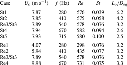
SPIV data were obtained for eight synthetic jet conditions in this experiment, covering a range of  $Re$ and
 $St$. A 3-D reconstruction of the resolution used in this study, for three phases of the actuator and the mean jet, generated a large amount of data. Therefore, the 3-D reconstruction was only performed at one jet condition. For all other cases, data were obtained on the centreline major axis and minor axis planes only.
The jet conditions tested are summarized in table 2 along with the case naming convention. To study the influence of varying  $St$ at a constant
 $Re$, the frequency of actuation was varied from 280 Hz to 715 Hz while the average blowing velocity was held constant. Conversely, to vary
 $Re$ while holding
 $St$ constant, both the actuator frequency and average blowing velocity had to be adjusted concurrently. Five Strouhal numbers (cases St1–St5) and four Reynolds numbers (cases Re1–Re4) were tested. The sweep in
 $Re$ and
 $St$ shared one common point which was chosen as the condition for the 3-D reconstruction (case Re3/St3).
Synthetic jet conditions tested.

Several characteristics of the early vortex rings produced by the actuator were extracted from the SPIV data at the various conditions tested. One such parameter was the initial circulation strength of the vortex ring. By the definitions used in this study, which are typical for reporting synthetic jet flows, the vortex circulation strength varied with both  $Re$ and
 $St$. For an ejection of fluid from an orifice with an arbitrary velocity programme,
 $u_o(t)$, the generated circulation is
 \begin{equation} \varGamma = \int_{0}^{T/2} \tfrac{1}{2} u_o^2 (t)\,\textrm{d}t. \end{equation}
Essentially, the circulation production depends on the strength of the blowing, its duration and its programme. Glezer (Reference Glezer1988) showed that the initial circulation of laminar vortex rings produced by different velocity programmes collapse to a straight line relation of the form
 \begin{equation} \frac{\varGamma}{\nu} = C_1P\frac{U_o L_o}{2\nu}, \end{equation}
where  $C_{1}$ is a fit constant and
 $P$ is the programme factor. Utilizing (2.1), (2.2) and (2.3), it can be shown that the left-hand side of (2.8) relates to
 $Re$ and
 $St$ as follows (note factors of two absorbed into the constant
 $C_{2}$):
 \begin{equation} C_1\frac{U_o L_o}{2\nu}=C_2\frac{U_o h}{\nu}\frac{U_o T}{h}=C_2Re\frac{1}{St}. \end{equation}
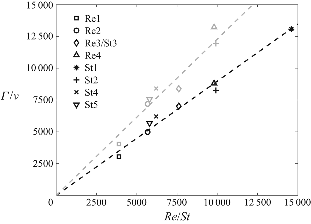
The peak circulation of the vortex rings formed in the synthetic jet was computed for all cases by integrating the SPIV field data around circuits defined using the contour of vorticity at 5 % of the maximum vorticity experienced for that jet condition. These data are presented in figure 8 using the non-dimensional form represented by (2.9). The circulation in the minor axis plane (black symbols) is lower than the major axis plane (grey symbols) due to a suspected branch in the vortex tube discussed in § 4.1. The data follow a linear trend (dashed lines) and confirm that the initial vortex ring circulation increases with  $Re$ but decreases with
 $St$.
Non-dimensional maximum circulation,  $\varGamma /\nu$, of the vortex ring at formation for the various
 $Re$ and
 $St$ tested. Black symbols represent circulation computed in the minor axis plane while grey symbols represent the major axis plane.

The shape of a pseudo-elliptic vortex ring, specifically the initial  $AR$, has a strong influence on whether bifurcation occurs and how it progresses (e.g. bifurcation vs trifurcation). Accordingly, an approximate initial vortex ring
 $AR$ was computed for the various conditions tested by measuring the distance of separation between the centres of the counter-rotating vortices in the major and minor centreline planes before axis switching deformations started. The results vary from
 $AR=7.9$ to
 $8.4$ but had an average of
 $AR=8.2$. Trends in
 $AR$ with changes in
 $Re$ and
 $St$ were too small relative to the uncertainty of the method to draw any conclusions. What can be stated with confidence is that the
 $AR$ of the vortex rings for all conditions tested exceeded the critical
 $AR$ for bifurcation reported in the literature.
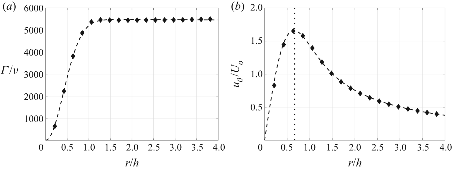
The size of the vortex core may also influence the progression of vortex ring bifurcation (Cheng et al. Reference Cheng, Lou and Lim2016). To quantify the vortex size, the circulation was found by integrating velocity along concentric circular paths of increasing radius centred on the vortex axis. Integration circuits were prevented from overlapping when two vortices of opposite sign were close to each other. The resulting  $\varGamma$ vs
 $r$ distribution was then fit with an Oseen–Lamb vortex profile (figure 9a). From the Oseen–Lamb profile fit, the core radius,
 $R_c$, was extracted as the distance between the vortex axis and the point where the average tangential velocity,
 $u_{\theta }$ reached a peak (figure 9b). Using this technique, the initial vortex core radius was found to vary from
 $R_c/h= 0.62$ to
 $0.79$ in the major axis plane and
 $R_c/h= 0.73$ to
 $0.86$ in the minor axis plane for all conditions tested. This calculation was performed on the individual frames that constitute the time-averaged data sets for a vortex height of
 $x/h=3.5$, which was the approximate point where the vortex was fully formed, i.e. had stopped accumulating additional circulation. The slightly higher values reported for
 $R_c$ in the minor axis plane are at least partially due to the asymmetry in the distorted cores of the proximate minor plane vortices. Any trends with increasing
 $Re$ or
 $St$ were again too small relative to the uncertainty in the calculation technique to allow for analysis. However, it is apparent from the data that the vortex rings produced at all conditions had wide cores relative to the ring's overall dimensions. Note that uncertainty bars have been omitted from figure 9 because the uncertainty was too low for the bars to be distinguishable from the data symbols. Furthermore, the diamond symbols representing the phased-locked SPIV data in figure 9 have the same spacing as the vectors in the measured velocity field and demonstrate that the vortex is well resolved in the measurements.
Vortex profile from phase-locked data ( $\blacklozenge$) with best fit to Oseen–Lamb vortex (
 ) and computed core radius (
 ) showing
 $(a)$ normalized circulation,
 $\varGamma /\nu$, and
 $(b)$ normalized tangential velocity,
 $u_{\theta }/U_o$, from minor axis plane of case Re3/St3,
 $\phi =90^{\circ }$.

3. Bifurcation structure and development
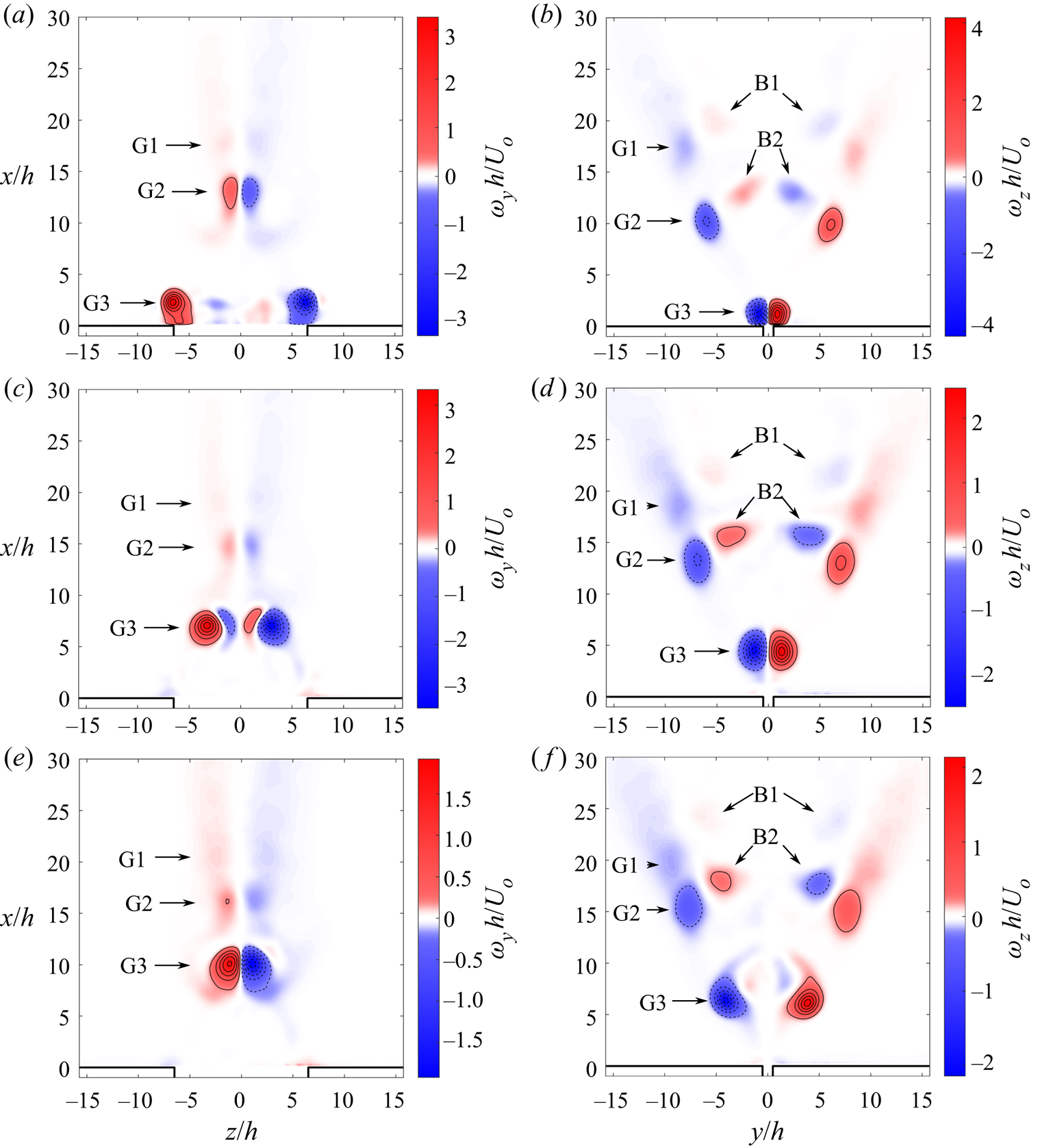
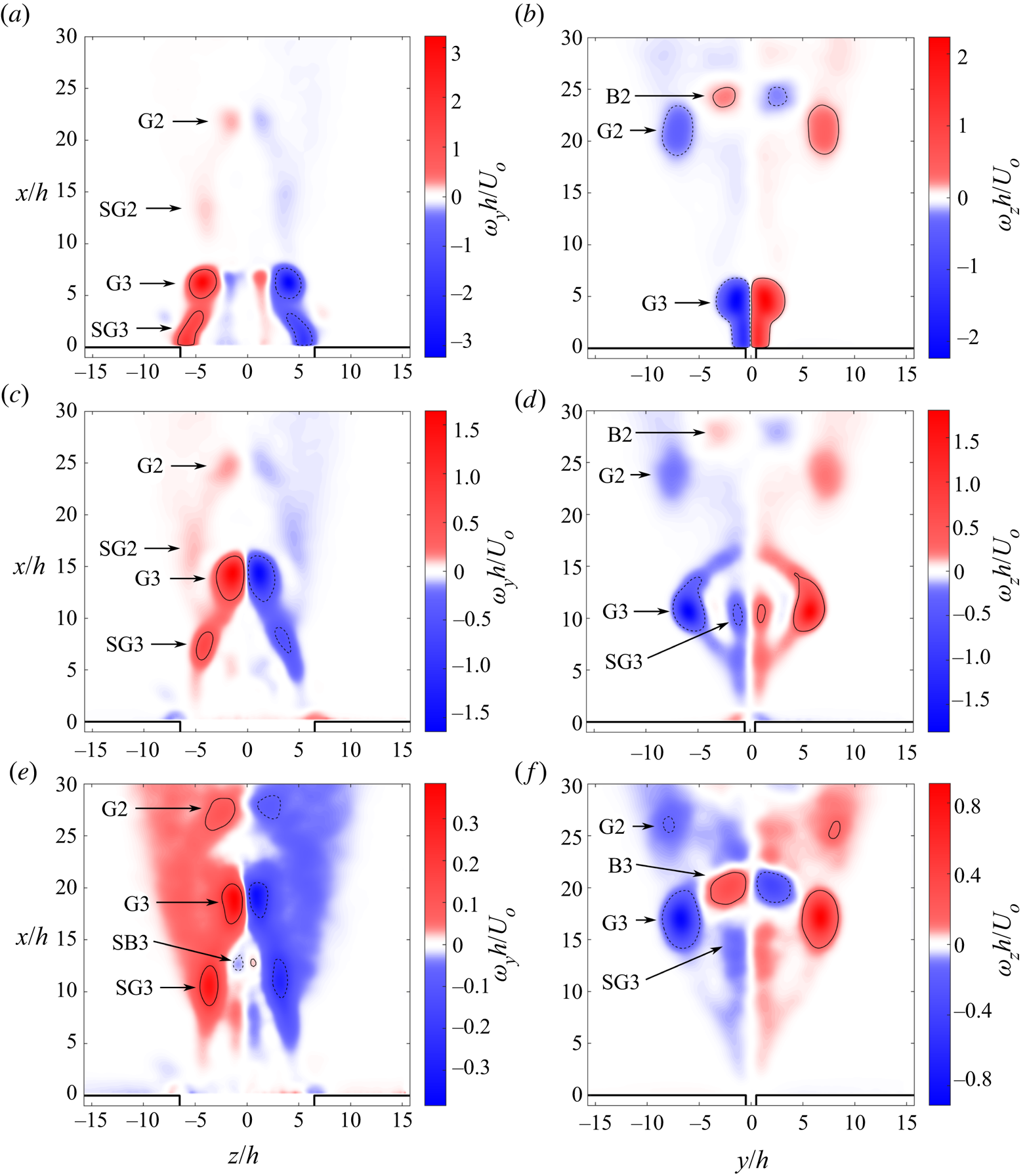
In this section, the structure and development of vortex ring bifurcation in synthetic jets is explored in detail for case Re3/St3 as summarized in table 2. Vortex ring bifurcation is a 3-D interaction involving large deformations in the ring, transfers of circulation between orthogonal planes, and the formation of a new vortex topology. Although the complete structure of this interaction cannot be ascertained from centreline measurements alone, valuable insight can be obtained by looking at data in these planes before progressing to the full 3-D flow field. Figure 10 presents phase-locked centreline measurements on the major axis (a,c,e) and minor axis (b,d,f) planes of the Re3/St3 jet. The filled contours delineate the magnitude of the out-of-plane vorticity with blue representing regions of negative vorticity, red regions of positive vorticity and white areas where vorticity is roughly zero. A nonlinear colour map is used in these contour plots to help accentuate structures of very different strengths. In addition, the contour range in each panel is scaled by its own extrema for the same reason. For presentation purposes, the vorticity field was computed utilizing (2.6). Three phases of the jet are plotted, where  $\phi =90^{\circ }$ (a,b) is approximately the time of peak blowing,
 $\phi =210^{\circ }$ (c,d) is shortly after the start of the suction phase and
 $\phi =330^{\circ }$ (e,f) is just before the end of the suction phase.
Contours of normalized out-of-plane vorticity for case Re3/St3 in the (a,c,e) major axis and (b,d,f) minor axis planes for phases (a,b)  $\phi =90^{\circ }$, (c,d)
 $\phi =210^{\circ }$ and (e,f)
 $\phi =330^{\circ }$. Contour lines drawn at
 $-90$,
 $-70$,
 $-50$,
 $-30$,
 $-10$, 10, 30, 50, 70,
 $90\,\%$ of maximum vorticity (
 ,
 $\omega <0$;
 ,
 $\omega >0$).

Starting with  $\phi =90^{\circ }$ (figure 10a,b), three generations of the vortex rings (G1, G2, G3) are captured with the youngest (G3) in the process of formation at the bottom of the frame near the orifice and the oldest (G1) almost completely dissipated at the top of the frame. In the minor axis plane, the two sides of the vortex ring are initially touching, whereas the vortices in the major axis plane are well separated due to the elongated shape of the orifice. By the next time step, the G3 vortex is fully formed and has propagated upwards away from the orifice due to self-induction (figure 10c,d). In the minor axis plane, the G3 vortices move straight upward like a 2-D dipole because the motion of each vortex is dictated mostly by mutual induction from their anti-parallel, rectilinear counterpart. In contrast, the vortices in the major axis plane move upward and inward due to the high local self-induction on the hairpin-shaped ends of the ring. Comparing the relative height of the G3 vortices in the two planes at
 $\phi =210^{\circ }$, it is obvious that the ends of the vortex ring in the major axis plane are travelling faster than the middle. The regions of counter-signed vorticity which have appeared between the G3 vortices in the major axis plane are a cross-stream secondary structure which will be discussed in § 4.1. At
 $\phi =330^{\circ }$, the G3 vortices in the minor axis plane spread abruptly as the vortex ring undergoes axis switching (figure 10e,f). Concurrently, the vortices in the major axis plane collide and at this phase are close enough for viscous cross-diffusion to annihilate and reconnect the innermost vortex lines. Due to this cross-linking, new regions of opposite signed vorticity appear between the spreading vortices in the major axis plane and are just barely visible at this phase. This vorticity will eventually consolidate into the bridge vortices on either side of the contact zone.
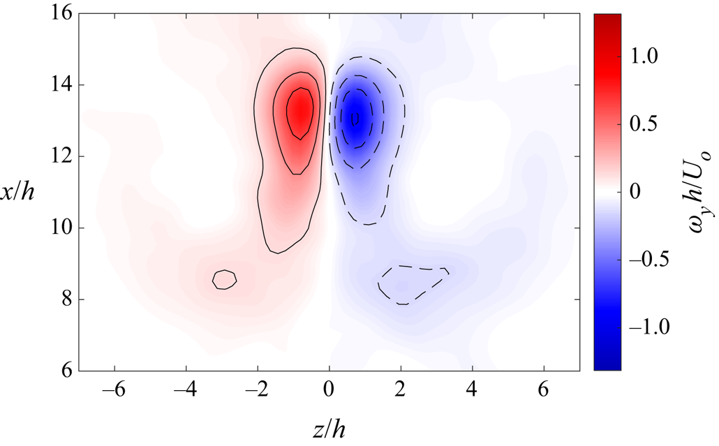
The next phase in the bifurcation process is reflected in the second generation (G2) vortex ring in figure 10. The bridge vortices (B2) continue to strengthen as new cross-linked vorticity appears, but the vorticity in the bridges is still significantly less intense than the outer primary vortices (figure 10b). This is due both to the comparatively lower circulation in the bridges and to the fact that new vortex lines recede outward due to self-induction after cross-linking, so the vorticity is not yet consolidated into a well-defined core (Kida et al. Reference Kida, Takaoka and Hussain1991a). Meanwhile, the dipole associated with the G2 vortex ring in the major axis plane at  $\phi =90^{\circ }$ has become weaker, and the vortex cores are significantly deformed (figure 10a). A close-up view of the vortex dipole presented in figure 11 reveals the classical head–tail structure of a vortex collision with the heads at the top of the dipole. Kida et al. (Reference Kida, Takaoka and Hussain1991b) showed that the head–tail structure is a product of the straining in the converging flow caused by self-induction from the curved vortex tubes. Specifically, horizontal stretching near the top of the dipole widens the head while vertical stretching in the lower dipole tends to lengthen the tail. Furthermore, the outward sweep of the tails away from the jet centreline appears to be a common feature of vortex collisions brought about by axis switching of an elongated vortex ring (Kida et al. Reference Kida, Takaoka and Hussain1991a; Wang et al. Reference Wang, Feng, Wang and Li2018a). The islands of elevated vorticity upstream of the dipole at a height of
 $x/h=8.5$ are associated with a secondary structure to be discussed in § 4.5.
Head–tail structure of colliding dipole from case Re3/St3 phase-locked data at  $\phi =90^{\circ }$ on major axis plane depicting normalized out-of-plane vorticity,
 $\omega _yh/U_o$, in coloured contours with black contour curves (
 ,
 $\omega _y<0$;
 ,
 $\omega _y>0$).

At  $\phi =210^{\circ }$, the G2 vortices have become much weaker in the major axis plane while the bridge vortices (B2) in the minor axis plane have become stronger at their expense (figure 10c,d). By
 $\phi =330^{\circ }$, vorticity reconnection has slowed significantly, and so the bridge vortices (B2) have not grown further in strength although their cores appear more compact. Meanwhile, in the major axis plane, the colliding vortices have diverged from each other slightly. These are the thread vortices left over after vorticity reconnection has essentially ceased. At all phases, the oldest vortices (G1) propagate slowly downstream while decaying. The bifurcated vortex rings continue to diverge away from each other as do the thread vortices.
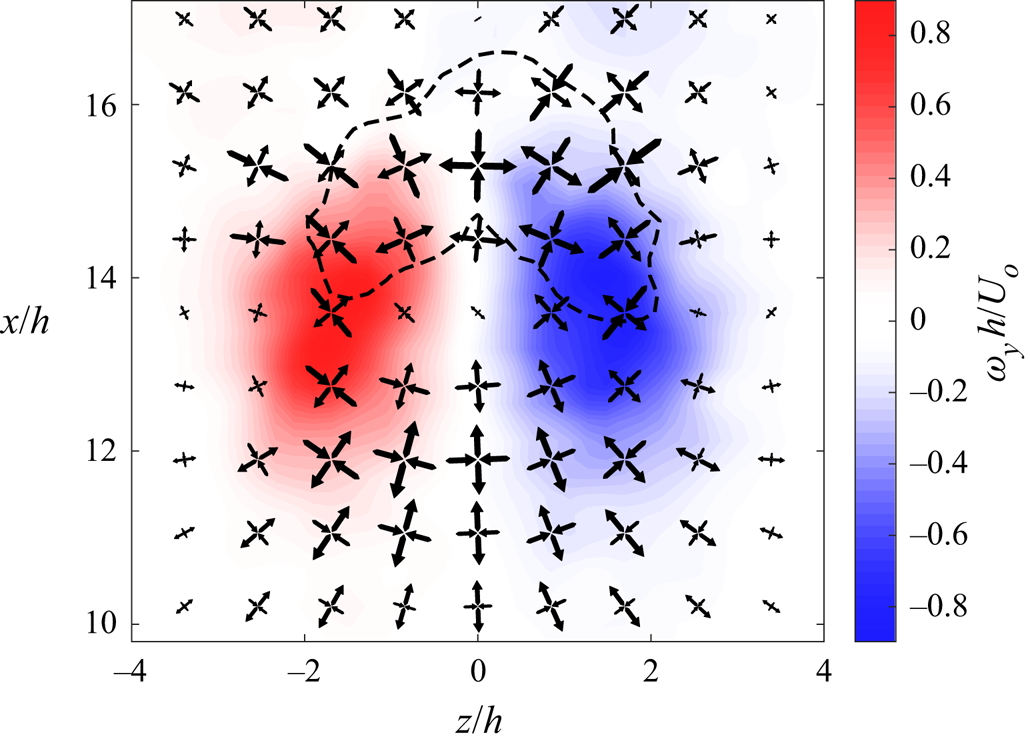
To explore the structure and formation of the bridge vortices, data on a plane offset 5 mm from the jet major axis plane at  $\phi =210^{\circ }$ are plotted in figure 12. This plane was chosen because it sits within the bridge vortex and is aligned with its long axis. The colour contours display the magnitude of the out-of-plane vorticity,
 $\omega _{y}$, revealing the cross section of the vortex ring. A single black, dashed contour curve shows in-plane vorticity
 $\omega _{z}$ at a level of 50 %
 $|\omega _z|_{min}$, which outlines the vorticity contained in the bridge vortex. Finally, overlaid on the contours are cruciform arrow patterns representing the in-plane strain rate field. The cruciform patterns are rotated to align with the principal angle, and the direction and relative length of the arrows indicate compression versus extension and the relative magnitude of the principle strains, respectively. The centre span of the bridge lies above the vortex dipole because the upwash within the dipole transports cross-linked vortex lines upwards (Melander & Hussain Reference Melander and Hussain1988). The ends of the bridge curve downwards towards the dipole vortices because the bridge is merely a branch in the outer vortex tube and eventually tilts into the
 $y$-direction and merges with the thread vortices to form the outer portion of the ring. It is apparent that the streamwise position of the bridge vortex centre span is roughly aligned with the point of maximum horizontal stretching in the strain rate field. During vorticity reconnection, cross-linked vortex lines are advected upwards by the dipole until they reach the point of maximum stretching where they accumulate in the bridge vortices (Kida et al. Reference Kida, Takaoka and Hussain1991a).
Bridge vortex structure in case Re3/St3 phase-locked data at  $\phi =210^{\circ }$ on
 $x$–
 $z$ plane 5 mm off centreline depicting normalized out-of-plane vorticity,
 $\omega _yh/U_o$, in filled coloured contours overlaid with black dashed contour curve for negative in-plane vorticity,
 $\omega _zh/U_o$, and cruciform arrow patterns representing the in-plane strain principal angle, direction and magnitude.

Insight into the evolution of the vortex from formation to decay can be obtained by tracking the vorticity at the vortex centre,  $\omega _{vc}$, and the vortex circulation strength,
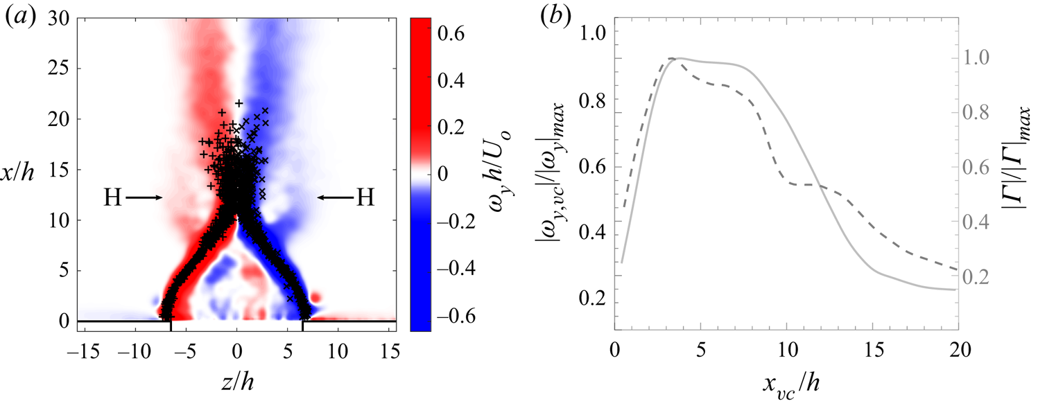
 $\varGamma$. This information was extracted from the 500 instantaneous measurements that constitute the time-averaged data set by the vortex identification and tracking techniques outlined in § 2.2. The location of the identified vortex centres in the major axis plane, after eliminating spatial outliers, is shown in figure 13(a). Circulation was computed using the vorticity contours at level 7.5 %
 $\omega _{max}$ to define the circuit of integration. Only contours which contained a vortex centre, as determined by the
 $\mathcal {Q}$-criterion, were assessed. Outlier detection logic was implemented to eliminate merged contours between two or more adjacent patches of vorticity. The spline curves fit to these instantaneous data are presented in figure 13(b) for the absolute value of circulation and vorticity versus vortex centre height,
 $x_{vc}$.
Jet development in major axis plane from Re3/St3 time-averaged data showing  $(a)$ colour contours of time-averaged out-of-plane normalized vorticity,
 $\omega _{y}h/U_o$, overlaid with individual frame vortex axis locations (
 $+$, CCW vortex;
 $\times$, CW vortex) and
 $(b)$ variation in magnitude of average circulation (
 ,
 $|\varGamma |/|\varGamma |_{max}$) and vorticity at vortex centres (
 ,
 $|\omega _{y,vc}|/|\omega _y|_{max}$) with vortex height,
 $x_{vc}$.

Initially, the shear layer produced by fluid ejected from the actuator during the blowing phase feeds the growing vortex. During this period of formation, the circulation and  $\omega _{vc}$ increase. The vortex is fully formed by a height of
 $x/h \approx 4$, and from figure 13(a) it is apparent that the convergence of the vortices towards each other due to the axis switching deformations has already begun. Up to a height of
 $x/h=8$ the vortices undergo inviscid advection during which circulation remains essentially constant and
 $\omega _{vc}$ drops slowly due to diffusion. At a height of
 $x/h=9$ the outer edges of the two vortices come in contact as indicated by the merging of the opposite signed vorticity regions in figure 13(a). The collision of the anti-parallel vortices initiates vorticity reconnection and therefore circulation declines as vortex lines are annihilated in the contact zone. The decline in
 $\omega _{vc}$ increases at this point because the larger vorticity gradient across the dipole drives more rapid diffusion. However, as the vortex ring starts bifurcating the thread vortices are stretched starting around
 $x/h=11$. The amplification of
 $\omega _{vc}$ due to stretching offsets the decline in
 $\omega _{vc}$ due to viscous cross-diffusion. Thus,
 $\omega _{vc}$ remains essentially constant up to
 $x/h=14$. Vortex stretching plays an important role in sustaining viscous cross-diffusion as the thread vortices become weaker. At a height of
 $x/h=15$ the significantly weakened thread vortices start to diverge (figure 10e). Additional vorticity reconnection continues at a much lower rate from this point forward. Above
 $x/h=18$, the data become sparse, but the trends suggest circulation declines much more slowly and the diffusion of vorticity returns to the pre-collision rate. The thread vortices now decay on the viscous time scale.
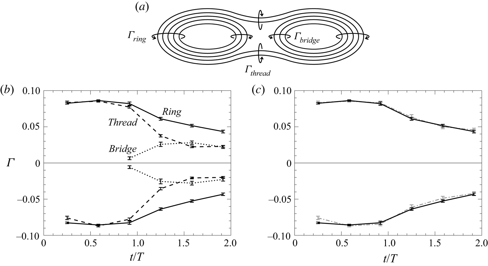
An interesting characteristic of vorticity reconnection is that, although vortex lines are annihilated by viscous cross-diffusion in the contact zone between colliding anti-parallel vortices, vorticity of equivalent circulation is reoriented into the orthogonal plane by vortex line cross-linking. This conservation of circulation during the viscous interaction can be confirmed by tracking its variations in the major and minor axis planes. To do this the circulation of the second and third generation vortices in the phase-locked average frames was computed on the two planes. In this case the circuits of integration were manually generated polygons enclosing the vortices. Manually defining the integration circuit allows the outer edges of the vortices to be included, unlike vorticity contour circuits, but is only feasible when the number of frames involved is small, as is the case here. The evolution of circulation with time in various parts of the vortex ring, depicted in figure 14(a), is shown in figure 14(b). Time is normalized by the period of the actuation cycle,  $T$, such that
 $t/T=0$ represents the start of the blowing phase,
 $t/T=0.5$ the start of the suction phase, and
 $t/T=1$ the end of that cycle. Parameter
 $\varGamma _{ring}$ represents the circulation of the vortex ring in the minor axis plane while
 $\varGamma _{bridge}$ corresponds to the bridge vortices which form in the same plane.
 $\varGamma _{thread}$ is the circulation of the vortices in the major axis plane which collide and eventually become the thread vortices. Initially,
 $\varGamma _{ring}$ is equivalent to
 $\varGamma _{thread}$ which we would expect for circulation measured on different sections of the same inviscid vortex ring. Around
 $t/T=0.75$,
 $\varGamma _{thread}$ starts to decline more rapidly than
 $\varGamma _{ring}$ due to the collision of the vortices in the minor axis plane. At the same time, the bridges start to appear (
 $\varGamma _{bridge}$) due to the reorientation of vorticity.
 $\varGamma _{bridge}$ continues to grow as the bridges strengthen at the expense of the dipole (
 $\varGamma _{thread}$) and concurrently the disparity between
 $\varGamma _{ring}$ and
 $\varGamma _{thread}$ increases. Eventually, the decline in
 $\varGamma _{thread}$ slows as the threads diverge while the strength of the bridge vortices (
 $\varGamma _{bridge}$) reaches a peak before starting to decay themselves.
Change of circulation,  $\varGamma$, with time,
 $t/T$, in different parts of the vortex ring for case Re3/St3 showing
 $(a)$ the location and rotational direction of the reported circulations,
 $(b)$ the variation in circulation in the outer part of the vortex ring (
 ) and in the thread (
 ) and bridge (
 ) vortices and
 $(c)$ a comparison of the circulation strength in the unperturbed outer vortex ring (
 ) with the summation of circulation in the thread and bridge vortices (
 ).

To confirm the spatial conservation of circulation during vorticity reconnection, the circulation in the colliding dipole ( $\varGamma _{thread}$) can be added to the circulation in the bridges (
 $\varGamma _{bridge}$) and compared with the part of the ring whose circulation is not affected by reconnection (
 $\varGamma _{ring}$) which is shown in figure 14(c). The results confirm that circulation is preserved in the flow field during vorticity reconnection. The comparison presented in figure 14(c) was made for all jet conditions tested and the conservation observation was confirmed in all cases except St1 due to the formation dynamics which will be discussed in § 4.2.
The vortex circulations computed in the minor axis plane can also be used to track the progress of bifurcation. By comparing the amount of circulation which has accumulated in the bridge vortex ( $\varGamma _{bridge}$) to the circulation in the outer part of the vortex ring which is outside of the contact zone (
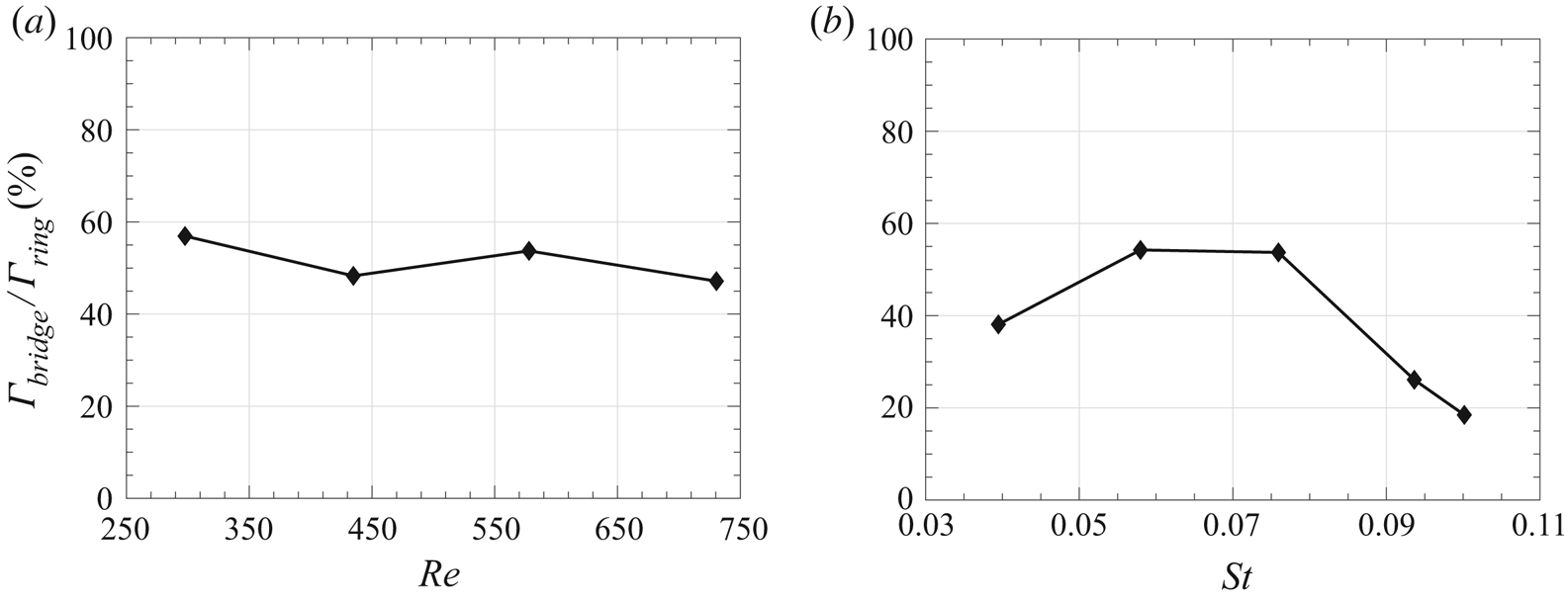
 $\varGamma _{ring}$), a reconnection completeness ratio
 $\varGamma _{bridge}/\varGamma _{ring}$ can be computed. The variation of
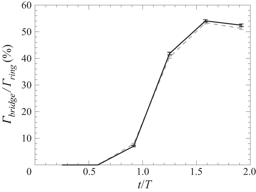
 $\varGamma _{bridge}/\varGamma _{ring}$ with time is presented in figure 15. Initially, all of the circulation is contained in the converging vortices in the major axis plane, but, by the end of the time surveyed, over 50 % of the circulation has been transferred to the bridge vortices by vorticity reconnection. Consistent with the simulations by Melander & Hussain (Reference Melander and Hussain1988) and Kida et al. (Reference Kida, Takaoka and Hussain1991a), vorticity reconnection – and thus the bifurcation – is far from complete at the time that the thread vortices diverge. In § 5, the peak value of
 $\varGamma _{bridge}/\varGamma _{ring}$ is presented for all jet conditions tested as a means of comparing the vortex ring bifurcation.
Variation in time,  $t/T$, of the percentage of the vortex ring total circulation which has been cut and reconnected in the bridge vortices,
 $\varGamma _{bridge}/\varGamma _{ring}$, for case Re3/St3 (
 ,
 $y<0$ side of vortex ring;
 ,
 $y>0$ side of vortex ring).

The change in the vortex topology brought about by the bifurcation of the ring has a measurable effect on the velocity field of the jet. The rotational sense of the bridge vortices is such that they mutually induce a downward velocity between them which decelerates the flow along the jet centreline (figure 14a). Outside of the bridge vortex pair, the bridge vortices induce an upward velocity on either side of the centreline. The result is that the traditional centre-weighted axial velocity profile transforms into a split-peak profile in the minor axis plane. Hussain & Husain (Reference Hussain and Husain1989) also detected additional peaks in the axial velocity profile of a bifurcating jet and used the feature as an indicator of when vortex ring bifurcation had occurred. The difference is that, in a continuous jet, a strong Gaussian velocity profile exists in the axial space between vortices, and so the mean velocity profile still has a prominent centreline peak in addition to the two smaller peaks distributed symmetrically around it. Alternatively, vortex rings are the primary mechanism for transporting momentum in the lower portion of synthetic jets, therefore, when the vortex ring bifurcates so does the axial momentum of the jet.
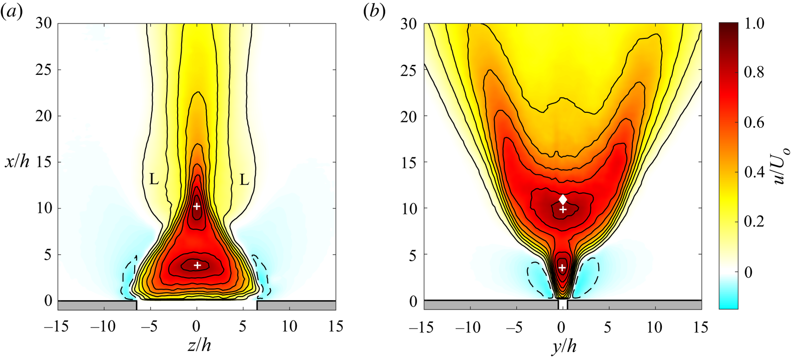
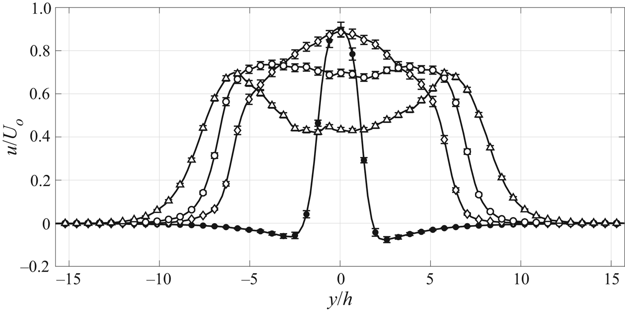
The redistribution of axial momentum in the minor axis plane is apparent in the contours of time-averaged axial velocity (figure 16b). Figure 17 also depicts the axial velocity profile across the width of the jet in this plane at a few key heights. On either side of the jet in figure 16, the dashed contours indicate regions of reversed flow caused by the suction phase of the actuator and the downward induction around the passing vortex rings. In the lower domain ( $x/h<4.5$), the jet is narrow and has a typical bell-shaped velocity profile (figures 16b and 17). However, above
 $x/h=4.5$, the jet spreads rapidly in the minor axis plane due to the axis switching of the vortex rings. By comparing the velocity profile at
 $x/h=3.7$ to
 $x/h=9.6$ it is evident that the axial momentum of the jet in this plane increases dramatically due to the reshaping of the jet (figure 17). Interestingly, the centreline velocity does not decay continuously in the streamwise direction, as would typically be expected, and instead has two maxima, one at
 $x/h=3.5$ and another at
 $x/h=9.8$ (indicated with
 $+$ symbols in figure 16). The trough between the two velocity maxima is a result of the variable shape of the vortex rings as they deform due to self-induction and occurs roughly at the height where the vortices in the major and minor axis are equidistance from the jet axis. Downstream of the second maximum, the centreline velocity falls faster than the outboard region of the jet, and at a height of
 $x/h=10.9$ (indicated with a diamond symbol in figure 16b) the axial velocity profile along the cross-stream direction develops a local minimum on centreline. The resulting split-peak velocity profile becomes more pronounced as the centreline flow continues to decelerate due to the increasing effect of the strengthening bridge vortices (see
 $x/h=12.4$ and
 $x/h=16.2$ profiles in figure 17). The point
 $x/h=10.9$, which marks the margin where the split-peak profile appears, will be referred to as the bifurcation height,
 $x_{bi}$, and used as a means of comparing the effect the jet conditions have on vortex ring bifurcation in § 5. In actuality, bifurcation is a gradual process which never runs to completion, so there is no single bifurcation point. However, the formation of the split-peak velocity profile indicates the strength of the bridge vortices relative to the rest of the vortex ring has exceeded a key threshold; therefore, the point at which it develops has physical relevance for the reconnection process.
Contours of time-averaged axial velocity for case Re3/St3 in the  $(a)$ major axis plane and
 $(b)$ minor axis plane. Black contour lines are every
 $10\,\%$ of
 $U_o$ from
 $-5\,\%$ to 85 % (
 ,
 $u<0$;
 ,
 $u>0$;
 $\blacklozenge$, bifurcation height;
 $+$, local velocity peak).

Spanwise profile of non-dimensional axial velocity,  $u/U_o$, across minor axis plane at four heights in the time-averaged Re3/St3 jet;
 $x/h = 3.7 \ (\bullet ), 9.6 \ (\lozenge ), 12.4 \ (\circ )$ and
 $16.2 \ (\triangle )$. Symbols plotted every three data points for clarity.

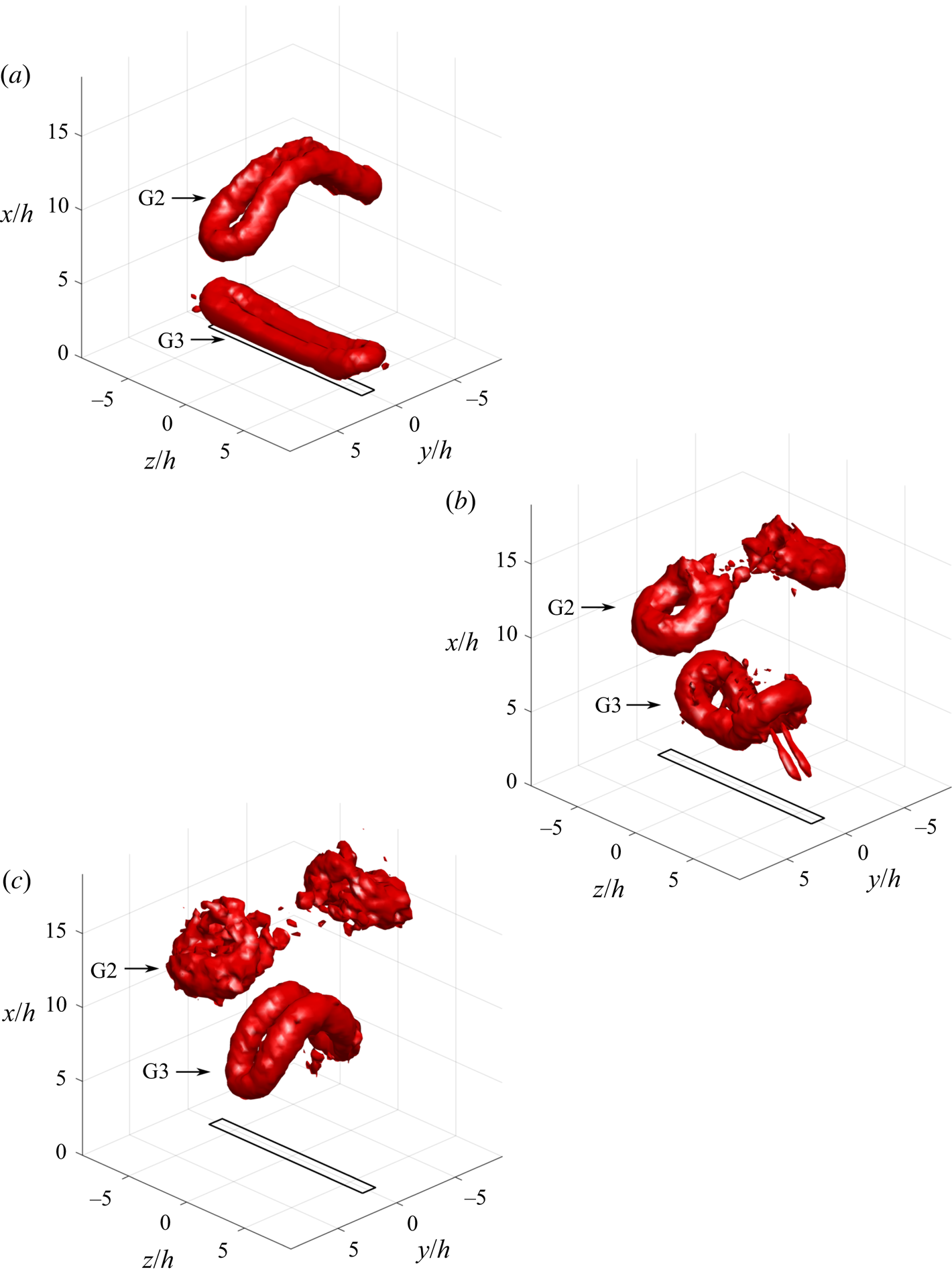
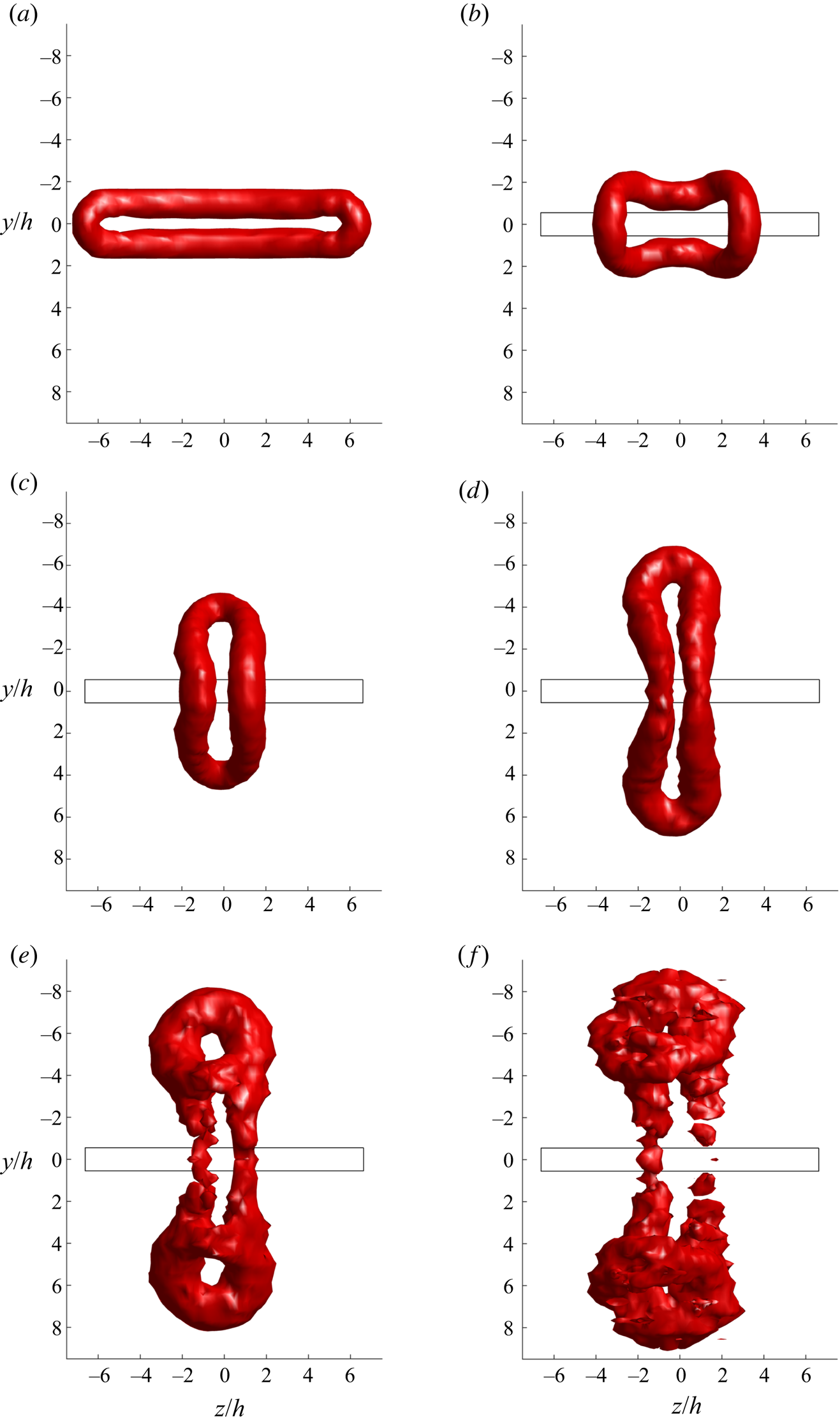
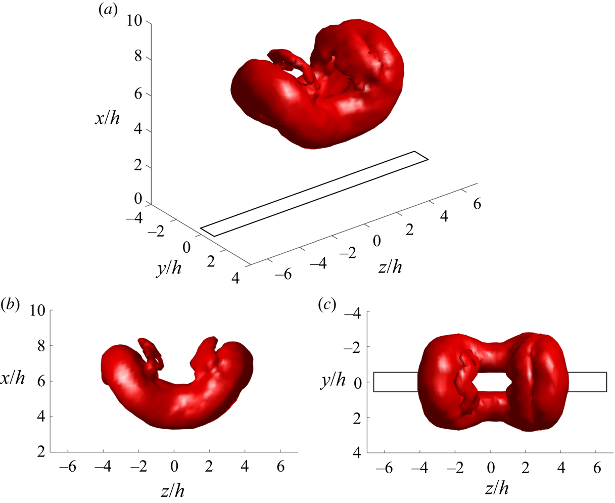
Although much can be gleaned from studying the synthetic jet on the centreline planes, the details of how the vortex ring bifurcation develops are dependent on the full vortex ring topology. Figure 18 depicts the three-dimensionally reconstructed vortex ring at three phases of the Re3/St3 jet  $(\phi = 90^{\circ },\ 210^{\circ },\ 330^{\circ })$. Plotted are isosurfaces of
 $\lambda _{ci}$ at
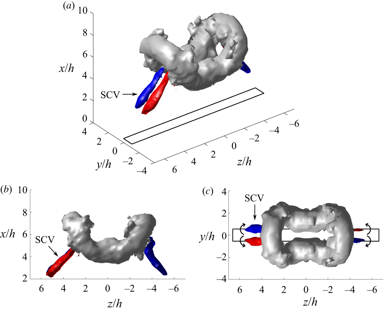
 $5\,\%$ of the maximum value in the domain. At this threshold two generations of vortex rings in the synthetic jet train are visible (G2 and G3). The third older vortex ring (G1), identified in figure 10, is not visible at this isosurface level because it has almost completely decayed and is relatively weak. The newest vortex ring (G3) in all three phases is undergoing axis switching deformations while the older (G2) is proceeding through vorticity reconnection and bridging. At
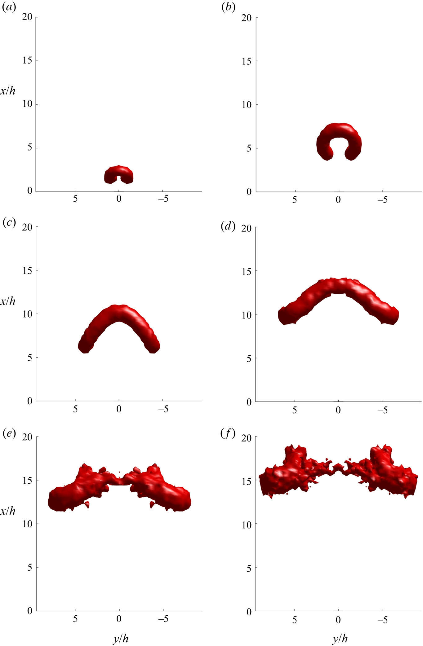
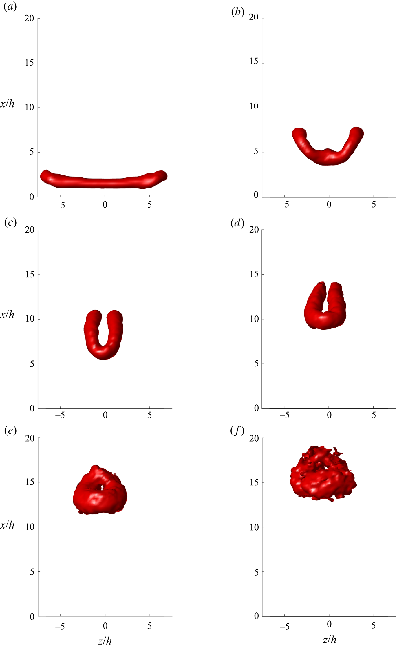
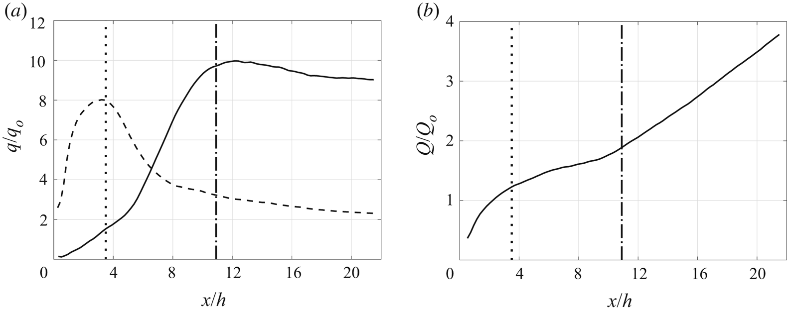
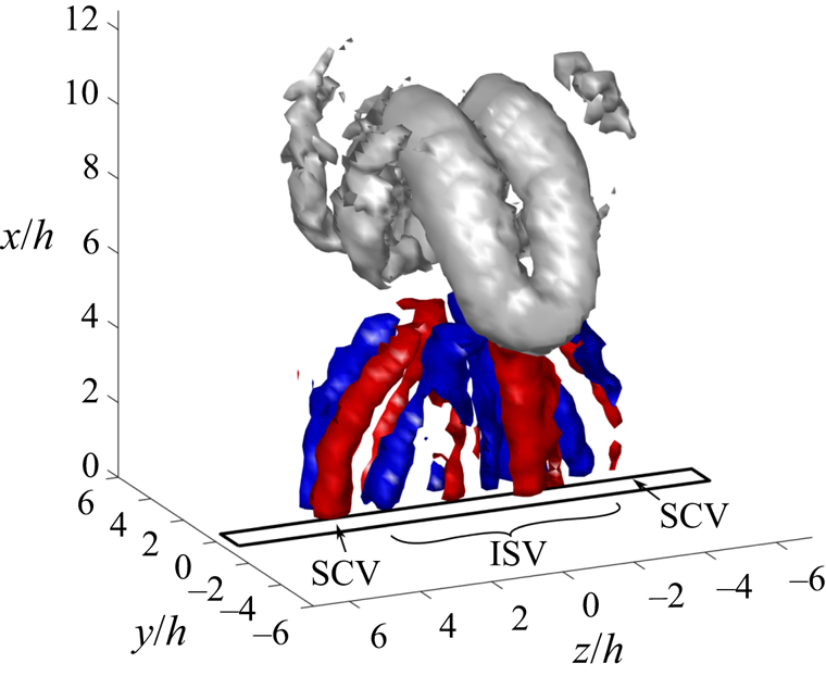
 $\phi =210^{\circ }$ the G3 vortex ring is surrounded by secondary structures which arise due to the deformations of the elongated vortex ring. These will be discussed in § 4. In general, it is difficult to select an isosurface level that isolates the primary structures of both the newer and older vortex ring from secondary structures because of the substantial difference in their strengths and coherence. To enable a clearer presentation of the vortex structure as it evolves, each phase of the vortex is spatially isolated in figures 19–21. The
 $\lambda _{ci}$ isosurface level is now set at 20 % of the local maxima instead of a fraction of the global extremum. An animation which shows the 3-D flow field reconstruction process and the development of the vortex ring bifurcation is available as supplementary movie 1 available at https://doi.org/10.1017/jfm.2020.616.
Axonometric projection of phase-locked  $\lambda _{ci}$ isosurface at 5 % of the maximum
 $\lambda _{ci}$ in the flow field at phases
 $(a)$
 $\phi =90^{\circ }$,
 $(b)$
 $\phi =210^{\circ }$ and
 $(c)$
 $\phi =330^{\circ }$ for case Re3/St3.

Top view of phase-locked  $\lambda _{ci}$ isosurface at 20 % of the local maxima in
 $\lambda _{ci}$ for case Re3/St3. Only the (a–c) G3 or (d–f) G2 vortex ring is shown at phase (a,d)
 $\phi =90^{\circ }$, (b,e)
 $\phi =210^{\circ }$ or (c,f)
 $\phi =330^{\circ }$.

Front view of phase-locked  $\lambda _{ci}$ isosurface at 20 % of the local maxima in
 $\lambda _{ci}$ for case Re3/St3. Only the (a–c) G3 or (d–f) G2 vortex ring is shown at phase (a,d)
 $\phi =90^{\circ }$, (b,e)
 $\phi =210^{\circ }$ or (c,f)
 $\phi =330^{\circ }$.

Side view of phase-locked  $\lambda _{ci}$ isosurface at 20 % of the local maxima in
 $\lambda _{ci}$ for case Re3/St3. Only the (a–c) G3 or (d–f) G2 vortex ring is shown at phase (a,d)
 $\phi =90^{\circ }$, (b,e)
 $\phi =210^{\circ }$ or (c,f)
 $\phi =330^{\circ }$.

At  $\phi =90^{\circ }$ the G3 vortex ring is almost fully formed and its shape and orientation mirror that of the orifice. In the side view, it is apparent that the ends of the vortex ring have already started to travel upward and inward faster than the rest of the ring due to high local self-induction on the high-curvature region of the vortex tube (figure 21a). By
 $\phi =210^{\circ }$ the difference in propagation speed is more pronounced. The ends of the vortex ring have moved further inboard and upwards while the middle of the ring is developing increasing curvature and has started to move outboard. At
 $\phi =330^{\circ }$ the G3 vortex ring is now wider in the minor axis plane than in the major axis plane and has developed a pinch at its centre. The vortices in the major axis plane have converged closely enough that the diffuse vorticity around their cores has started to collide and annihilate. This is not obvious from the
 $\lambda _{ci}$ isosurface because of the level of the threshold but can be confirmed in the minor axis vorticity contour plot at that phase (figure 10e). The self-induced deformations continue to broaden the G2 ring in the minor axis plane at
 $\phi =90^{\circ }$. Viewed from the top, the vortices in the contact zone are narrower than the rest of the vortex due to streamwise elongation of the cores and a reduction in the vortex size is observed due to vorticity annihilation (figure 19d). The proximity of the vortices required for vorticity reconnection is maintained because the upward bow in the vortex tube around the centreline, visible in figure 20(c,d), results in a self-induced velocity which drives the dipole together. The vortices are also being locally stretched which intensifies the vorticity gradient. Both factors accelerate the rate of vorticity annihilation in the contact zone.
For G2 at  $\phi =90^{\circ }$ the bridge vortices are still not visible in the
 $\lambda _{ci}$ isosurface, but they have started to form, which is evident from the spots of diffuse vorticity in figure 10(b). Two processes are responsible for the development of the bridge vortices: vorticity reconnection which increases the bridges’ circulation, as well as stretching in the diverging flow above the dipole which concentrates and intensifies the bridges’ constitutive vorticity (figure 12). By
 $\phi =210^{\circ }$ for G2 this development is advanced enough that the mature bridge vortices are detectable above the isosurface threshold (figure 19e). The bridges are positioned above the rest of the vortex ring due to the upwash induced by the dipole and have receded away from the contact zone due to stretching and self-induction on their hairpin-like shape. At this point, the circulation in the bridges has exceeded that of the dipole vortices which are now referred to as threads (figure 14). The strengthening downward induction from the bridge vortices has begun to flip the threads from being bowed downstream to bowed upstream, as sketched in figure 3(e,f). The change in the sign of curvature of the thread vortices causes the direction of local self-induction to flip which now drives the thread vortices apart. As a result, vorticity reconnection slows (see
 $x/h=15$ in figure 13). The vortex topology now resembles two roughly circular vortex rings instead of a single elongated ring (G2 vortex ring in figure 18b).
After this topological bifurcation, the vortex rings quickly decay. By  $\phi =330^{\circ }$ the bridge vortices of the G2 vortex ring are no longer growing in strength and the outer part of the vortex ring has lost approximately two thirds of its original circulation. Consequently, the propagation speed of the vortex rings has slowed significantly since formation, causing these rings to pile up with other slowly moving vortex rings from previous generations at the downstream end of the measurement domain (figure 10).
The streamwise volume flux per unit depth of the jet in the minor and major axis planes is plotted in figure 22(a). The in-plane flow rate,  $q$, was computed by integrating the jet axial velocity across the plane in the domain where
 $u(x)>0.01*u_{max}(x)$ and non-dimensionalized by
 $q_o=U_oh$ in the minor axis plane or
 $q_o=U_ol$ in the major axis plane. Note that
 $u_{max}(x)$ is the maximum axial velocity at a height of
 $x$ in the jet. Uncertainty bands have been omitted from figure 22 because the uncertainty was too low for the bands to be distinguishable from the data curves. In both planes the flow rate at the orifice is zero, which is a feature of zero-net-mass-flux actuators. The volume flux in the minor axis plane grows gradually at first, but the rate increases suddenly around
 $x/h=5.5$. This is a manifestation of the vortex ring axis switching, which rapidly broadens the jet in this plane, instead of being brought about by an equivalent increase in the jet entrainment. Once the vortex ring's axes switch, it bifurcates and the rate of change of the volume flux drops off to a slightly negative slope in the upper jet. Alternatively, the volume flux in the major axis plane grows very rapidly up to
 $x/h=3.5$ while the vortex is forming but then drops almost as quickly as the vortex ring axis switches and the jet contracts in that plane. Vortex rings induce an upward velocity within the region enclosed by the ring and a downward velocity in the region outside of the ring. When the ring contracts in a plane due to axis switching deformations, regions which previously experienced accelerated upwards flow are replaced with downwards induction. This is why planar volume flux drops rapidly above
 $x/h=3.5$ in the major axis plane. Van Buren et al. (Reference Van Buren, Whalen and Amitay2014a) reported very similar variations in the mass flow rate in the centreline planes of an
 $AR=6$ synthetic jet. The peaks, abrupt changes in rate, and regions of declining volume flux are caused by taking a two-dimensional view of the complex 3-D dynamics of the non-circular jet.
Axial variation in  $(a)$ non-dimensional in-plane volume flux,
 $q/q_o$, in the minor axis (
 $x$–
 $y$) plane (
 ) and major axis (
 $x$–
 $z$) plane (
 ) and
 $(b)$ total non-dimensional volume flux,
 $Q/Q_o$, (
 , height of fully formed vortex ring;
 , bifurcation height).

Figure 22(b) presents the 3-D volume flux integrated across the whole jet for  $u(x)>0.01*u_{max}(x)$ non-dimensionalized by
 $Q_o=U_ohl$. The steady rise in the volume flux presented in this figure aligns more with the expected behaviour of a jet than the planar results in figure 22(a). Volume flux starts at zero at the orifice and increases rapidly up to
 $x/h=3.5$ while the vortex is forming. After the vortex is formed, the entrainment rate drops gradually until a height of
 $x/h=9.5$. At this point, which corresponds to the height where intense vorticity reconnection starts, the entrainment rate increases and maintains a constant value out to the edge of the calculation domain. In the lower jet, one can reconcile the 3-D flux with the in-plane rates because while flow rate is slow in one plane, it is fast in the other, a relationship which switches at a height of
 $x/h=6.5$. The rapid changes of planar volume flux,
 $q$, are indicative of a redistribution of axial momentum within the jet and not changes in entrainment. In the upper jet, however, both centreline planes have declining planar volume flux while the 3-D volume flux increases linearly. Entrainment occurs at the bounding envelope of the jet. After vortex ring bifurcation, the bridge vortices induce a downwards velocity between the vortex rings and simultaneously the centreline flow speed decays due to diffusion of momentum. Consequently, the centreline planes encompass much of the area of the jet where axial velocity declines. An interrogation of the 3-D
 $du/dx$ field reveals that above the bifurcation height, the majority of flow axially accelerated by either vortex-induced momentum redistribution or entrainment exists in the four quadrants of the jet, not in the major or minor axis planes. Therefore, the volume flow rate data from the centreline planes are not an accurate indication of the 3-D development of the jet.
Without a comparison to a similar synthetic jet for which the vortex rings do not bifurcate, it is not possible to say definitively what the effect of vortex ring bifurcation was on the jet entrainment rate. However, figure 22(b) reveals that the entrainment rate increased at the same axial position as the previously identified bifurcation height, which suggests that the entrainment rate was enhanced by vortex ring bifurcation. Hussain & Husain (Reference Hussain and Husain1989) came to the same conclusion applying basic principles, arguing that the ‘large increases in the vorticity boundary (of the two rings and threads) and associated vortex stretching, suggest that bifurcation is an efficient mechanism for mixing and enstrophy cascade’.
4. Secondary structures
The volumetric reconstruction of the synthetic jet in this study revealed several secondary vortical structures in the flow field. Some of these structures were very weak, registering only slightly above the noise floor in the turbulent jet; however, even these weak structures left identifiable marks on the jet. Secondary structures can have important implications for mixing and entrainment, and one will be shown to also influence the vortex ring bifurcation process. Therefore, a discussion of them is warranted. Furthermore, re-examination of prior work in light of these results will reveal the tell-tale signs of these structures in other studies of synthetic jets, confirming their ubiquity.
In this section, five secondary structures will be discussed in the order in which they form during the actuation cycle. Four of these structures are believed to develop at all conditions tested, but will be presented in case Re3/St3 because the structures are easier to visualize in the 3-D flow field reconstruction. The remaining structure is specific to the lowest  $St$ cases and will be explored in case St1.
4.1. Vortex formation bridges
The first structures of interest form with the vortex ring during the blowing phase. They start as regions of diffuse, counter-rotating cross-stream vorticity ( $\omega _y$) inside the vortex ring, i.e. between the primary vortex pair, and are bisected by the major axis plane (figure 10a). As the vortex ring propagates away from the orifice and contracts due to self-induction in the major axis plane, these cross-stream structures advect upwards and inwards towards the jet axis. The cross-stream vorticity is at first concentrated by the convergence of the vortex ring and is then rolled up and over the stronger primary vortex pair. This induced motion is visible at
 $\phi =210^{\circ }$ in figure 10(c) where the structures appear as arcs in the ensemble average frame due to variability in their instantaneous positions around the stronger primary vortex (i.e. jitter). As the cross-stream structures are compressed against the primary vortices, their vorticity annihilates and they essentially disappear by the time they have revolved to the outside of the jet (figure 10e). In the time-averaged data, these structures appear as streamwise streaks of vorticity inside the jet (figure 13). They were observed for all conditions tested, although the number of counter-rotating sets increased with
 $St$.
In the domain where the cross-stream vorticity exists, the flow is subject to an elevated strain rate due to the deformations of the adjacent vortex ring. Therefore,  $\mathcal {Q}$ and
 $\lambda _{ci}$ criteria fail to capture the full extent of these structures and tend to misidentify the location of their centroids. To visualize them it is thus preferable to plot isosurfaces of vorticity magnitude,
 $|\omega |$, as presented in figure 23. At this phase, the cross-stream vorticity appears to be part of a bridge which is connected to and spans the vortex ring. Although these structures are not well identified by the
 $\lambda _{ci}$ criterion, in figure 18(b), the points where they connect to the vortex ring are visible as lumps projecting from the vortex surface. When circulation was computed around the early vortex ring using integration circuits which excluded the secondary cross-stream vorticity, the circulation was found to be variable around the vortex ring (figure 8). More specifically, the circulation at the ends of the vortex ring in the major axis plane was higher than the circulation at the middle of the vortex ring in the minor axis plane. However, when the integration circuits were redrawn to also encompass the secondary vorticity, the circulation was found to be remarkably consistent around the ring (figure 14).
Isosurface of  $|\boldsymbol {\omega }|$ at 15 % of
 $|\boldsymbol {\omega }|_{max}$ for case Re3/St3 at
 $\phi =210^{\circ }$:
 $(a)$ axonometric projection,
 $(b)$ side view and
 $(c)$ top view.

The 3-D topology and circulation data suggest that the cross-stream vorticity may be a vortex tube branch off of the primary vortex ring. Like the bridge vortices formed during bifurcation, these too appear to arise due to vorticity reconnection. The vortex rings generated by the SJA are in direct contact across the minor axis. By  $\phi =300^{\circ }$ the vortex cores in the minor axis plane vorticity contours (figure 10d) and the
 $\lambda _{ci}$ isosurface (figure 21b) are also elongated in the streamwise direction. This proximity and core distortion in anti-parallel vortices establishes a contact zone across which vorticity reconnection is known to occur. Vorticity annihilation by viscous cross-diffusion reduces the circulation of the primary structure at the contact zone while vorticity reconnection feeds bridges that contain the redistributed vorticity. This continues until axis switching of the vortex ring separates the vortices.
Bifurcation or trifurcation of vortex rings with sufficiently large  $AR$ shortly after formation was predicted in simulations by Kiya et al. (Reference Kiya, Toyoda, Ishii, Kitamura and Ohe1992) and Menon & Soo (Reference Menon and Soo2004). The present results may therefore represent a marginal case where vorticity reconnection occurs but is insufficiently complete to cause the vortex ring to bifurcate or cease axis switching. Kiya et al. (Reference Kiya, Toyoda, Ishii, Kitamura and Ohe1992) indicated this may have been the case in their complementary experiment with an
 $AR=8.3$ pseudo-elliptic vortex ring. Therefore, we call these new regions of vorticity ‘formation bridges’ to differentiate them from the bridge vortices which occur after the vortex ring has switched axes. As the vortex ring undergoes axis switching deformations, these formation bridges are stretched and then annihilated against the tops of the primary vortices. Similar dynamics is presented by Kida et al. (Reference Kida, Takaoka and Hussain1991a) in figure 4(b) (v–viii).
Secondary structures, which are potentially related to the formation bridges outlined here, have been observed in similar studies. Amitay & Cannelle (Reference Amitay and Cannelle2006) detected counter-rotating sets of cross-stream vorticity inside the major axis of rectangular orifice synthetic jets with  $AR=50.8, 76.2$ and
 $101.6$. They found that, as stroke length increased, the number of structures decreased. This is equivalent to our finding that increased
 $St$ led to more of the secondary structures. Amitay & Cannelle (Reference Amitay and Cannelle2006) also found that, as
 $AR$ of the jet was increased, so did the number of structures. Van Buren et al. (Reference Van Buren, Whalen and Amitay2014a, figure 14) supports the same conclusion for
 $AR=6, 12$ and
 $18$ orifice synthetic jets. The dependence of the number of counter-rotating cross-stream vorticity sets on stroke length and orifice
 $AR$ may both be related to azimuthal waves in the vortex ring. When jet conditions or vortex ring geometry allow for higher modes of azimuthal fluctuations, the vortex ring could make contact in more places along the major axis, and so more sets of formation bridges would be generated.
4.2. Vortex pinch-off and secondary vortex rings
At the lowest  $St$ tested,
 $St = 0.039$ (St1), a unique secondary structured formed below the vortex ring which was also associated with the formation process of the vortex. At these conditions a significant amount of unincorporated vorticity remained in the shear layer upstream of the vortex ring above the orifice. As the primary vortex ring advected upwards, instability in the shear layer led to the formation of a secondary vortex ring (labelled SG3 in figure 24).
Contours of normalized out-of-plane vorticity for case St1 in the  $(a{,}c{,}e)$ major axis and
 $(b{,}d{,}\,f)$ minor axis planes for phases
 $(a{,}b)$
 $\phi =110^{\circ }$,
 $(c{,}d)$
 $\phi =230^{\circ }$ and
 $(e{,}\,f)$
 $\phi =350^{\circ }$. Black contour lines drawn at select levels to highlight structures (
 ,
 $\omega <0$;
 ,
 $\omega >0$).

Vortex rings form when the shear layer produced by fluid expulsion through an orifice or nozzle rolls up into a spiral of concentrated vorticity. As more turns of the spiral accumulate, the vortex ring grows in diameter and strength (Didden Reference Didden1979). This process cannot continue indefinitely, however. Gharib et al. (Reference Gharib, Rambod and Shariff1998) determined that the growth of circular vortex rings reaches a critical limit beyond which the vortex ring cannot accumulate additional circulation. Physically, this happens because, as the vortex circulation increases so does the self-induced velocity of the vortex ring. At the limiting condition, the speed of the vortex ring exceeds the speed of the shear layer and so the ring outruns the shear layer and pinches off from it. Gharib et al. (Reference Gharib, Rambod and Shariff1998) showed that the non-dimensional formation time or formation number for a circular vortex ring was  $L/D\approx 4$. The vorticity produced by the piston stroke, after
 $L/D=4$ has been exceeded, remains in a detached tail behind the pinched-off vortex ring. Conversely, experimental studies and computational analysis of 2-D or infinite vortex pairs have shown that either these vortices do not have a critical formation number or that this number is significantly higher than
 $L/D=4$ (Afanasyev Reference Afanasyev2006; Pedrizzetti Reference Pedrizzetti2010). The computational analysis by Domenichi (Reference Domenichi2011) predicted that elongated vortex rings with curved ends and a rectilinear mid-section could exhibit both behaviours at different points along their circumference, i.e. pinching off on the curved ends but not on the rectilinear mid-section. However, O'Farrell & Dabiri (Reference O'Farrell and Dabiri2012) found experimentally that oval and elliptical vortex rings pinched off everywhere at the same time, with
 $L/D\approx 3-4$.
The case with the highest stroke length in this study, St1, had an  $L_o/D_{eq}=6.2$ which exceeds the formation number proposed by Gharib et al. (Reference Gharib, Rambod and Shariff1998). The more moderate St2 had an
 $L_o/D_{eq}=4.2$, only slightly above the limit, while the remaining six cases were well below
 $L_o/D_{eq}=4$ (table 2). Figure 24 depicts the vorticity field in the major and minor axis planes for case St1. During the blowing phase, a relatively strong shear layer can be seen upstream of the developing G3 vortices (figure 24a,b). In the minor axis plane the shear layer is still attached to the vortex, however, in the major axis plane it is already apparent that the vortex ring has started pinching off. Earlier pinch-off in the major axis plane is to be expected because the tightly curved ends of the elongated vortex rings will travel downstream faster than the rectilinear mid-section. During the next phase, instability causes the now separate shear layer to develop into a secondary vortex ring denoted SG3 (figure 24c,d). These results can be compared with Re3/St3 (
 $L_o/D_{eq} = 3.2$), which represents a typical case where there is no secondary vortex ring formation (figure 10).
As the primary vortices in case St1 converge in the major axis plane, the secondary vortices trail behind them and converge at a similar rate (figure 24c,e). In the minor axis plane, however, as the primary vortices spread apart, they induce the secondary structures upwards and between them (figure 24d,f). Therefore, parts of the secondary structure appear to partially pass through the primary structure leading to a highly distorted shape. This partial pass-through of the secondary vortex ring also appears to have been captured in flow visualizations by Adhikari (Reference Adhikari2009).
The circulation in G3 and SG3 was computed in the major axis plane at  $\phi =230^{\circ }$ around manually defined integration circuits with the saddle point in the vorticity contours between the primary and secondary vortices used to demarcate where one vortex ended and the other began. The results revealed that 66.8 % of the total circulation generated in the flow field by that actuator stroke was contained within the primary vortex ring or, in other words, G3 was twice as strong as SG3. In theory, the vortex ring will pinch off at a formation number of
 $L/D=4$ so for the case St1, which had a stroke length of
 $L_o/D_{eq}=6.2, 64.5\%$ of the total circulation generated should accumulate in the primary vortex ring. This is remarkably close to the results obtained from the SPIV measurements.
Interestingly, the secondary vortices appear to be weaker in the minor axis plane than in the major (compare figures 24c and 24d). This is not due to the variable pinch-off predicted computationally by Domenichi (Reference Domenichi2011) because this trend is opposite the theory that elongated vortex rings accumulate more circulation in rectilinear sections. Instead, the cause is vorticity reconnection brought about by the collision of opposite sides of the secondary vortex ring as it is squeezed through the primary ring in that plane. Evidence of this vorticity reconnection in the secondary vortex ring can be seen in the final measurement phase where secondary bridge vortices (SB3) appear in the expected location (figure 24e). In the same figure, it is also noteworthy that the primary vortex, G3, now appears to have approximately equivalent strength to SG3 despite G3 being much stronger in the prior phase. The culprit is again vorticity reconnection; however, this time it occurs in the primary vortex ring and in the opposite direction. The resulting bridge vortices (B3) can be found in figure 24(f).
In the minor axis plane at  $\phi =350^{\circ }$ a discreet secondary vortex SG3 is no longer obvious in the phase-locked data (figure 24f). Instead, the streamwise streak of vorticity suggests variability in the position of SG3 between the instantaneous measurement frames that make up the phase-locked ensemble average. What is apparent is that the secondary vortex ring is in a similar downstream location as the colliding region of the primary vortex ring. The interaction between the primary and secondary vortex rings has important implications for vortex ring bifurcation at these conditions, as will be discussed further in § 5.
A similar region of pinched-off vorticity was also identified in the vorticity field of case St2 during the blowing phase. However, the secondary structure was difficult to precisely locate in the other two phase-locked data sets due to its low strength. Regardless, the results presented in § 5 suggest that even in this marginal case the pinched-off vorticity may weakly interact with the primary vortex ring in some manner.
The conditions which produced vortex pinch-off in this study are not extreme, in terms of typical SJA operation. Indeed, evidence of this behaviour is common, if not always discussed, in the other publications of synthetic jet data. For example, vortex pinch-off can be observed in the vorticity fields presented by Amitay & Cannelle (Reference Amitay and Cannelle2006) (figures 8(c) and 8(f) where  $L_o/h=49.4$ is equivalent to
 $L_o/D_{eq}=6.14$) and Van Buren, Whalen & Amitay (Reference Van Buren, Whalen and Amitay2014b) (figure 12 where
 $St=0.046$ and
 $0.028$ are equivalent to
 $L_o/D_{eq}=4.54$ and
 $7.46$, respectively).
4.3. Streamwise corner vortices
Later in the jet phase and upstream of the primary vortex ring, four streamwise vortices – specifically two counter-rotating sets – are apparent in the coloured isosurfaces of  $\lambda _{ci}$ marked ‘SCV’ in figure 25. These streamwise vortices stretch from the ends of the rectangular orifice up to mid-section of the newest vortex ring. Similar coherent structures have been detected in continuous jets from elliptic and square nozzles (Husain & Hussain Reference Husain and Hussain1993; Grinstein & DeVore Reference Grinstein and DeVore1996), in isolated vortex rings from elliptic nozzles (Adhikari Reference Adhikari2009) and in synthetic jets from rectangular orifices (Wang et al. Reference Wang, Feng, Wang and Li2018a). They are the result of tilting and stretching induced by the deformed primary vortex ring. To understand their formation, it is helpful to think of the cylindrical shear layer that precedes the vortex ring as a train of coaxial vortex lines that encircle the jet. As the shear layer rolls up starting from its downstream end, the vorticity is concentrated into the nascent vortex ring core. A small amount of residual vorticity remains in the upstream section of the shear layer which has classically been referred to as the braid region of continuous jets (this is sketched as a dashed line in figure 3a). These unconsolidated braid vortex lines are much weaker than the vortex ring; therefore, their celerity and rate of self-induced deformation is much slower. Instead, the much stronger nearby vortex ring has a dominant influence on the changing shape of the vortex lines. As the highly curved ends of the elongated vortex ring move ahead of its middle, the greatest velocity induction on the braid vortex lines occurs in the region where their separation distance is at a minimum, i.e. the mid-section. Thus, they deform in a manner which is the opposite of the primary ring, i.e. the middle moves downstream faster than the ends (see dashed line marked ‘SCV’ in figures 3b–3d). The uneven induction from the primary vortex ring has the effect of tilting the originally spanwise oriented vorticity (
 $\omega _z$) into the streamwise direction (
 $\omega _x$). Furthermore, the tilting of these vortex lines tends to consolidate this sparse vorticity while stretching intensifies it into the streamwise corner vortices.
Isosurface of  $\lambda _{ci}$ at 4 % of
 $\lambda _{ci,max}$ for case Re3/St3 at
 $\phi =210^{\circ }$:
 $(a)$ axonometric projection,
 $(b)$ side view and
 $(c)$ top view with arrows indicating rotational direction (blue, streamwise corner vortices with
 $\omega _x<0$; red, streamwise corner vortices with
 $\omega _x>0$; grey, primary vortex ring).

The streamwise corner vortices exist in the four quadrants of square, rectangular and elliptic jets and therefore do not cross the centreline planes where experimental data are frequently obtained. Thus, they are often undetected in experimental studies of synthetic jets, as was true for the cases in this study that did not include a 3-D flow field reconstruction. Despite this difficulty, their presence may be significant. For one, as the vortices are tilted and intensified by stretching they induce flow normal to the jet axis. This tends to enhance entrainment (Liepmann & Gharib Reference Liepmann and Gharib1992; Husain & Hussain Reference Husain and Hussain1993) and can cause the ejection of flow out of the jet between each counter-rotating pair (Gutmark & Grinstein Reference Gutmark and Grinstein1999). In addition, the interaction of the streamwise vortices with the primary vortex ring can also inhibit axis switching (Grinstein & DeVore Reference Grinstein and DeVore1996) and influence the structure of the vortex ring in such a way as to accelerate instability, transition and breakdown (Liepmann & Gharib Reference Liepmann and Gharib1992; Gutmark & Grinstein Reference Gutmark and Grinstein1999; Adhikari Reference Adhikari2009).
4.4. Interstitial streamwise vortices
The streamwise corner vortices were not the only streamwise structures identified upstream of the vortex ring. Analysis of the three-component vorticity field revealed additional sets of counter-rotating structures along the jet's span. We refer to these as interstitial streamwise vortices due to their position between the corner vortices. Vorticity associated with the nascent interstitial streamwise structures is present at phase  $\phi =210^{\circ }$, but the structures are too immature to be detected via vortex identification techniques like
 $\mathcal {Q}$-criterion or
 $\lambda _{ci}$. By
 $\phi =330^{\circ }$ some of the interstitial streamwise vortices have become coherent enough to appear in
 $\lambda _{ci}$ isosurfaces; however, a more complete view of the structures can be obtained by plotting the vorticity field. Figure 26 depicts isosurfaces of streamwise vorticity,
 $\omega _x$, coloured by rotational sense (blue,
 $\omega _x<0$; red,
 $\omega _x>0$) upstream of the primary vortex ring while other structures in the vicinity are plotted using isosurfaces of
 $\lambda _{ci}$ coloured grey. Six to eight sets of counter-rotating streamwise vortices can be identified in the figure. The outermost vortex sets are the streamwise corner vortices (SCV) identified in the prior phase, while the inner sets constitute multiple pairs of the interstitial streamwise vortices (ISV). Some of the interstitial streamwise vortices are also visible in the isosurfaces of
 $\lambda _{ci}$ in figure 27.
Isosurface of  $\omega _x$ at 1.5 %
 $\omega _{x,min}$ (blue) and 1.5 %
 $\omega _{x,max}$ (red) with isosurface of
 $\lambda _{ci}$ at 3 % of
 $\lambda _{ci,max}$ (grey) for case Re3/St3 at
 $\phi =210^{\circ }$.

Isosurface of  $\lambda _{ci}$ at 3 % of
 $\lambda _{ci,max}$ for case Re3/St3 at
 $\phi =330^{\circ }$:
 $(a)$ axonometric projection,
 $(b)$ side view and
 $(c)$ top view with arrows indicating rotational direction (green, arc-shaped vortices; grey, primary vortex ring and streamwise secondary structures).

Sets of streamwise vortices distributed along the span of synthetic jets have also been reported in other studies. For example, Amitay & Cannelle (Reference Amitay and Cannelle2006) speculated that streamwise structures were present inside their synthetic jets based on traces left on the centreline plane cross-stream vorticity fields. They hypothesized that the streamwise structures were related to azimuthal waves in the primary vortex ring during transition. However, we are not aware of any study which definitively identifies the formation mechanism.
The formation process may be related to rib vortex generation in the braid regions of shear layers (Bernal & Roshko Reference Bernal and Roshko1986) and continuous jets (Liepmann & Gharib Reference Liepmann and Gharib1992; Husain & Hussain Reference Husain and Hussain1993). However, unlike shear layers and continuous jets, there is no upstream primary or roll vortex in the synthetic jet at this phase to stretch the streamwise structure in the opposite direction as the downstream vortex ring. The timing of the appearance and development of the interstitial vortices may provide a hint as to how they form. At  $\phi =210^{\circ }$ the streamwise vorticity associated with the vortices had just started to appear while by
 $\phi =330^{\circ }$ the interstitial vortices were well established. These phases correspond to the point in the actuation cycle shortly after the start of the suction phase and shortly before the end of the suction phase, respectively. Therefore, the suction cycle in synthetic jets may have an equivalent role in streamwise vortex formation as induction from an upstream vortex in continuous jets. However, if the interstitial vortices form from the vorticity sheet in the braid region, like streamwise corner vortices or rib vortices, it would imply that the sketch of vortex lines in figure 3 is oversimplified. The picture of how these structures come to be is obviously incomplete; as a result, additional work is required to ascertain the details of interstitial streamwise vortex formation in synthetic jets, and to determine if they are equivalent to the rib vortices found in other flows.
4.5. Arc-shaped structures
The self-induced deformations of the non-circular vortex ring also lead to the generation of secondary structures downstream of the ring. Slightly after their formation, these appear as two sets of counter-rotating vortices wrapped around the primary vortex ring in the green  $\lambda _{ci}$ isosurfaces marked ‘ASV’ in figure 27. These structures are much weaker than the vortex ring, and so the isosurfaces containing their cores appear broken and irregular in the figure.
These structures form slightly later than the streamwise vortices at a phase when the ends of the vortex ring in the major axis plane are approaching the jet centreline. Similar structures have been reported by Adhikari (Reference Adhikari2009) and O'Farrell & Dabiri (Reference O'Farrell and Dabiri2012) for experiments with isolated elliptic vortex rings in water and by Wang et al. (Reference Wang, Feng, Wang and Li2018a) for a synthetic jet in water. Adhikari (Reference Adhikari2009) referred to them as ‘arc-like structures’. To the authors’ knowledge they have not been previously reported in synthetic jets formed in air, presumably due to the difficulty of identifying such weak structures at higher  $Re$. At the conditions for the present experiment, the full topology of the arc vortices could not be extracted. Nor was sufficient temporal resolution obtained to determine the precise mechanism of their formation. Wang et al. (Reference Wang, Feng, Wang and Li2018a) suggested that the two counter-rotating, streamwise vortex sets on either side of the deforming vortex ring were part of a single loop-shaped structure based on their experiment with an
 $AR=3$ rectangular orifice synthetic jet in water. This possible topology is sketched out in figures 3(c) and 3(d) as a dash-dotted line marked ‘ASV’. However, unlike Wang et al. (Reference Wang, Feng, Wang and Li2018a), Adhikari (Reference Adhikari2009) and O'Farrell & Dabiri (Reference O'Farrell and Dabiri2012) who tested nozzle
 $AR$ values between 2 and 5, no discernible vortex pair was seen in the minor axis plane, which should bisect such a structure. Therefore, the arc-shaped vortices may have a different topology near the axis of moderate
 $AR$ synthetic jets.
It has been shown in other studies that arc-like vortices are formed from the same residual shear layer vorticity as the streamwise corner vortices discussed in § 4.3 (Adhikari Reference Adhikari2009). In the minor axis plane, the outward travelling sections of the vortex ring move downstream slower than the jet centreline velocity, and so a section of the shear layer passes through the centre of the vortex ring and overtakes its minor axis. The high extensional strain rate with spanwise elongation in the flow downstream of the vortex ring stretches the shear layer fluid, which causes the vorticity to be amplified and concentrated into the arc-shaped vortices. Details on the formation process of these structures are provided by O'Farrell & Dabiri (Reference O'Farrell and Dabiri2012). Continued induction from the comparatively stronger vortex ring eventually wraps the arc vortices around itself such that the ends of the secondary structure reside upstream of the ring.
The presence of these arc-shaped vortices has several effects on the jet flow field. First, the two arc-shaped vortices have a rotational sense which mutually induces higher momentum fluid inside the jet radially outward from the jet axis. Note that the formation bridges may also contribute to this jet outflow. The transported fluid appears as lobes of elevated momentum at the edge of the jet in the major axis plane around  $x/h=8-20$ (labelled ‘L’ in figure 16a). These lobes occur at a streamwise position in the major axis plane where one would expect the jet to contract if only the axis switching of the primary vortex ring was considered. Therefore, we can infer that these secondary structures enhance mixing of the non-circular jet. Similar lobes of elevated momentum can be identified in figure 2(b) (ii) of Van Buren & Amitay (Reference Van Buren and Amitay2016) for an
 $AR=12$ rectangular orifice synthetic jet.
The arc-shaped vortices also leave a tell-tale sign in the major axis plane vorticity contours. The semi-circular ends connecting the two arc-shaped structures appear as two islands of elevated vorticity below the primary vortex ring at a height of  $x/h = 8.5$ in the phase-locked data presented in figure 11. As the ends of the secondary structure are rolled around the travelling vortex ring, they sweep out two arcs that wrap back into the manifold of the jet. This appears as two ‘horn’ shaped projections of vorticity away from the jet axis in the time-averaged vorticity contours (labelled ‘H’ in figure 13). Similar vorticity ‘horns’ can again be found by careful inspection of the vorticity contour plot in figure 7(b) (ii) of Van Buren & Amitay (Reference Van Buren and Amitay2016) for an
 $AR=12$ rectangular orifice synthetic jet.
The ‘horn’ shaped vorticity contours were present for all conditions tested. They did not change appreciably with  $Re$ but were dependent on
 $St$. Specifically, as
 $St$ increased, the angle the ‘horns’ made with the jet axis was reduced from roughly
 $45^{\circ }$ to almost
 $0^{\circ }$, indicating the arc-shaped vortices remained closer to the main jet. This decreasing protrusion of the arc-shaped vortices from the jet with increasing
 $St$ is reflected in a reduction of the major axis plane normalized entrainment rate in the upper jet.
5. Effect of synthetic jet conditions on vortex ring bifurcation
In addition to exploring how vortex ring axis switching and bifurcation develop in synthetic jets, this study also sought to investigate how the synthetic jet conditions affected these dynamical phenomena. To this end, the jet  $Re$ and
 $St$ (i.e. inverse stroke length) were varied independently as summarized in table 2.
Vortex ring axis switching and bifurcation affect the mean shape of a synthetic jet. This is detectable in the jet half-width profile,  $\delta _{1/2}(x)$. Therefore, by comparing the jet widths at different jet conditions, insight into the effect of the jet conditions on the vortex dynamics can be obtained. Figure 28 depicts the variation in the time-averaged, normalized jet half-width with axial distance from the orifice in the minor axis plane. The edge of the jet was designated as the point where the jet velocity was 50 % that of the maximum velocity at that height. Note that the local velocity is compared to the maximum velocity at that height and not the centreline velocity. This was done to account for the split peak in the axial velocity profile above the height of bifurcation (see figure 17). The effect of varying
 $Re$ while holding
 $St$ is captured in figure 28(a). The shape of the jet reveals that, although the strength and celerity of the vortex ring increases with
 $Re$, the spatial development is unaffected. The consistency in the jet's shape implies that vortex ring self-induced deformations and bifurcation were not sensitive to changes in
 $Re$ within the range studied.
Normalized jet half-width,  $\delta _{1/2}(x)/h$, in minor axis
 $(x\text {--}y)$ plane for the different
 $(a)$
 $Re$ and
 $(b)$
 $St$ conditions tested.

Alternatively, for the cases where  $St$ was varied while holding
 $Re$, the shape of the jet did change (figure 28b). In the lower part of the jet, all of the cases follow the same spreading rate up to a height of
 $x/h=9$, except St1. The similarity of the jet spreading close to the orifice for cases St2–St5 imply an insensitivity of the vortex ring self-induced deformations to the spacing of vortex rings in the jet. The deviation of the outlier case St1 from this trend is due to the vortex pinch-off and the resulting secondary vortex ring discussed in § 4.2. The acceleration of the secondary structure into the central region of the primary vortex ring by mutual induction appears to prevent the primary vortices in the major axis plane from converging as quickly or as closely. This in turn delays the spreading of the jet in the minor axis plane as seen in figure 28(b) between
 $x/h=5$ and
 $x/h=10$.
Above  $x/h=9$, the continued spreading of the jet is enabled in part by the splitting of the vortex ring into two smaller rings which continue along on independent paths. The differences in the spreading in the upper jet between the
 $St$ cases suggest that the height of the vortex ring bifurcation and possibly the divergence angle of the separated vortex rings were affected by the jet
 $St$. To confirm this hypothesis, the height of vortex ring bifurcation (
 $x_{bi}$), defined by the appearance of a split peak in the axial velocity profile as described in § 3, is shown in figure 29. Consistent with the jet half-width data, varying
 $Re$ while holding
 $St$ did not affect the height above the orifice where the vortex rings bifurcated. In contrast, the vortex rings in the synthetic jets with the lowest
 $St$ bifurcated further from the orifice than the high
 $St$ cases. At the highest three
 $St$ tested, for which
 $L_o/D_{eq}$ was less than 4.0, the height of vortex ring bifurcation appears to be essentially the same. Therefore, for the range of
 $St$ tested, the vortex formation number had a stronger effect on bifurcation height and the jet width in the minor axis plane than did the proximity of the primary vortex rings.
Normalized vortex ring bifurcation height,  $x_{bi}/h$, for the different
 $(a)$
 $Re$ and
 $(b)$
 $St$ conditions tested.

Although the height of the vortex ring bifurcation affects the shape of the synthetic jet, the completeness of the bifurcation is the more critical factor influencing the redistribution of momentum and also provides insight into the intensity and duration of the vorticity reconnection. The circulation in the outer vortex ring,  $\varGamma _{ring}$, and the bridge vortices,
 $\varGamma _{bridge}$, was computed from the phase-locked data in the minor axis plane using manually drawn polygonal circuits (see figure 14a for naming convention). Bifurcation completeness is the ratio of these circulation values (
 $\varGamma _{bridge}/\varGamma _{ring}$) reported as a percentage. The maximum bifurcation completeness achieved for each of the conditions tested are presented in figure 30. Uncertainty bars have been omitted from this figure because the uncertainty was too low for the bars to be distinguishable from the data symbols. Figure 30(a) reveals that bifurcation completeness remained essentially constant at around 48 %–58 % when the Re of the jet was varied.
Vortex ring bifurcation completeness ratio,  $\varGamma _{bridge}/\varGamma _{ring}$, for the different
 $(a)$
 $Re$ and
 $(b)$
 $St$ conditions tested.

When  $St$ was varied, however, the bifurcation completeness changed significantly (figure 30b). Specifically, the bifurcation completeness was highest at the mid-
 $St$ values and dropped off at the lowest and highest
 $St$ values tested. This seemingly counter-intuitive finding is the result of two different mechanisms. For higher
 $St$ the close spacing of primary vortex rings in the jet leads to enhanced mutual induction effects which alter the vortex ring shape. The fact that the bifurcation is weaker for these cases implies that the mutual induction tends to reduce the closeness of the two sides of the dipole during the collision in the major axis plane. A similar widening of the upstream vortex ring by mutual induction is well known when two circular vortex rings undergo a pass-through or leap-frog interaction. One would expect that, as
 $St$ is reduced and the spacing between the primary vortex rings increased, the bifurcation process in the synthetic jet would asymptotically approach the behaviour of an isolated vortex ring. Indeed, the four highest
 $St$ values tested appear to follow that trend with only the lowest
 $St$ case, St1, deviating from it. The high stroke length and associated secondary vortex ring is responsible for the unique behaviour of the St1 jet. In this case, the secondary vortex ring, which forms from pinched-off vorticity, is induced upwards towards the centre of the primary vortex ring where it interferes with the colliding dipole, reducing the pace of vorticity reconnection.
To verify the hypothesis that lower bifurcation completeness was due to a larger separation distance between the colliding vortices, the paths of the vortices in the major axis plane were extracted. This was done by processing the individual frames that constitute the time-averaged data set to find the instantaneous locations of the vortex centres. The aggregate vortex locations from the 500 measurements were then fit with spline curves, and the  $z$-separation distance between those curves from the two sides of the jet was found. Figure 31(a) depicts the vortex separation distance,
 $\Delta z_{vc}$, in the major axis plane for all five
 $St$ cases. In addition, the minimum vortex separation distance is plotted in figure 31(b). As postulated from the bifurcation completeness results at the lowest and highest
 $St$, the colliding vortices do not approach as closely as the vortices in the mid-
 $St$ cases. In general, there is a good correlation between bifurcation completeness ratio and minimum vortex separation distance.
Dipole spanwise separation distance in the major axis  $(x\text {--}z)$ plane:
 $(a)$ variation in normalized vortex separation distance,
 $\Delta z_{vc}/h$, with height above orifice and
 $(b)$ variation in minimum separation distance between vortices with
 $St$.

6. Discussion and concluding remarks
The centreline plane and multi-planar 3-D reconstruction of a synthetic jet from SPIV data confirm that vortex ring bifurcation does occur in synthetic jets for a range of practical operating conditions. Furthermore, the progression of vortex ring axis switching and vorticity reconnection captured in figures 18–20 shares many similarities with the numerical simulations of isolated vortex rings by Melander & Hussain (Reference Melander and Hussain1988), Kida et al. (Reference Kida, Takaoka and Hussain1991a), Grinstein (Reference Grinstein1995) and Cheng et al. (Reference Cheng, Lou and Lim2016). Although many excellent experimental studies have investigated vortex ring bifurcation using flow visualization techniques and hot-wire anemometry, the 3-D, three-component velocity fields obtained with SPIV allow for unique comparisons with computational simulations. Wang et al. (Reference Wang, Feng, Wang and Li2018a) were possibly the first to utilize SPIV to approximately reconstruct vortex ring bifurcation in a low  $Re$ synthetic jet. However, their use of Taylor's hypothesis instead of multi-planar data yielded isosurfaces which are temporal amalgamations that may not faithfully represent the quickly deforming vortex structure as it actually existed. In the present study, painstaking multi-planar data acquisition allowed for true phase-locked isosurfaces of the vortex structure to be extracted as it underwent the processes of axis switching, secondary structure generation, bifurcation and, finally, decay.
Utilizing the SPIV data from the centreline planes, circulation accounting indicates that circulation was spatially conserved during vorticity reconnection around the vortex ring, i.e. the sum of the circulation in the bridge and thread vortices is equal to the circulation elsewhere in the ring. The same observation has been made in prior numerical studies; however, the present study is one of the first to give credence to this finding experimentally. Once the bridge vortices accumulated a sufficient proportion of the ring's circulation the axial velocity profile spanning the minor axis plane developed a split double peak due to the downward velocity induction between the bridges. In continuous jets, vortex ring bifurcation produces an axial velocity profile with three peaks, one of which is a prominent peak along the jet centreline. Therefore, the split double velocity peak identified in this study at all conditions tested is one of the ways vortex ring bifurcation in synthetic jets differs from that of continuous jets.
Despite the many similarities between vorticity reconnection in isolated vortex rings and the vortex rings of a synthetic jet, the unique conditions in synthetic jets give rise to distinct vortex ring bifurcation dynamics. Vortex ring bifurcation and the general development of the jet were essentially unaffected by changes in  $Re$, for the range tested in this study, while
 $St$ had a strong effect on both. At low
 $St$ the vortex formation time exceeded the pinch-off limit and leftover vorticity accumulated into secondary vortex rings, sections of which were later induced upward into the centre of the primary ring. This interaction reduced vorticity reconnection in the primary vortex ring and induced vorticity reconnection in the secondary ring. Conversely, at sufficiently high
 $St$, the primary vortices became more tightly spaced and mutual induction became strong enough to interfere with the bifurcation process. Therefore, vortex ring bifurcation was most complete at
 $St = 0.06\text {--}0.08$, for which the distance of separation from other vortex rings was largest. The effect other proximate vortices have on vortex ring bifurcation was not explored in the prior studies reviewed in this paper.
Another notable difference between the findings of this experiment and those of prior simulations of isolated vortex rings is the ultimate fate of the two adjacent vortex rings produced by bifurcation. The simulations by Grinstein (Reference Grinstein1995) and Cheng et al. (Reference Cheng, Lou and Lim2016) predicted that the vortex rings would turn in towards each other and ultimately collide and recombine. However, in the present experiment – for all conditions tested – the bifurcated vortex rings diverged on outward pointing trajectories before decaying to turbulence. The collision and recombination of the bifurcated vortex rings was also not reported in the flow visualization experiments by Kambe & Takao (Reference Kambe and Takao1971), Dhanak & Bernardinis (Reference Dhanak and Bernardinis1981) and Kiya et al. (Reference Kiya, Toyoda, Ishii, Kitamura and Ohe1992) who investigated isolated vortex ring bifurcation. Several factors could explain why experimental observations have differed from simulations. For one, the angle between the two vortex ring paths may be too divergent for induction to turn them onto converging trajectories. The initial  $AR$ and shape of the original vortex ring could explain differences in the orientations of the vortex rings at the point of bifurcation. However, it is worth noting that the range of
 $AR$ values and shapes tested in the flow visualization experiments outlined above overlap with those simulated in the numerical studies. The vortex rings may also decay or breakdown to turbulence too quickly for such a process to play out. However, the vortex ring
 $Re$ tested experimentally also appear to overlap with the range of conditions simulated numerically in those studies. Interestingly, in a later study Grinstein, Fureby & DeVore (Reference Grinstein, Fureby and DeVore2005) were able to produce either outcome (i.e. bifurcated vortex rings that either collide or do not collide) at the same conditions by merely changing the flux-corrected transport limiter used in their unsteady implicit large-eddy simulations. These results highlight that differences in subgrid-scale modelling can have important implications for how modelled fluctuations affect larger resolved structures and thereby produce macroscopic differences later in the simulation (Grinstein, Margolin & Rider Reference Grinstein, Margolin and Rider2007, pp. 265–291). Therefore, whether the two vortex rings produced by bifurcation converge and recombine in numerical simulations may also depend on the accuracy of turbulence modelling and the predicted transition dynamics.
In addition to vortex ring bifurcation, several secondary structures were also resolved in the 3-D flow field reconstructions. These included cross-stream formation bridges, corner vortices, streamwise interstitial vortices, arc-shaped vortices and secondary vortex rings. Analysis of the vortex isosurfaces and circulation data led to a theory that the cross-stream secondary structures observed in this and other experimental studies may in some cases be a branch of the vortex tube connected to the vortex ring which was formed by vorticity reconnection. The 3-D reconstructions also detected arc-shaped structures which appear to be responsible for the horns of vorticity and axial velocity lobes seen around the jet in the major axis plane of this and other studies of similar  $AR$ synthetic jets.
A number of centreline plane flow features were also linked with vortex ring bifurcation. Awareness of these tell-tale signs, and the knowledge of how they change according to the synthetic jet conditions, provides a key for identifying the same phenomena in similar studies. For example, the study by Van Buren et al. (Reference Van Buren, Whalen and Amitay2014a) of synthetic jets in quiescent conditions included flow field measurements for actuators with similar orifice geometries to the present work. Reviewing their figures reveals likely signs of vortex ring bifurcation. When analysing the streamwise velocity across the minor axis plane Van Buren et al. (Reference Van Buren, Whalen and Amitay2014a) observed that the  $AR=6$ orifice jet developed a split-peak profile in figure 7(a) and speculated that this may have been due to secondary structures. Upon reanalysis, it appears this split in the jet velocity peak may be the effect of bifurcation of the primary vortex structure caused by the downward induction from the bridge vortices. This theory is bolstered by the phase-locked vorticity contours for the minor axis plane of the
 $AR=6$ orifice jet (figure 12a) which contain regions of counter-rotating vorticity inside of the vortex ring in the position where one would expect to find bridges vortices. A different study from Van Buren & Amitay (Reference Van Buren and Amitay2016) has the same signs of vortex ring bifurcation (see figures 2a and 8a). The
 $AR=6$ orifice associated with those results is considerably different than the
 $AR$ utilized in the present study, although it is not a stretch to speculate that the vortex ring
 $AR$ values were still greater than the proposed critical limit for bifurcation (
 $AR=4-5$). What is surprising is that Van Buren et al. (Reference Van Buren, Whalen and Amitay2014a) also tested an
 $AR=12$ rectangular orifice, but the results from that actuator do not show obvious signs of vortex ring bifurcation despite it being more geometrically similar to the present study.
The explanation for this discrepancy may lie in the synthetic jet operating conditions. The  $St$ used in the experiment by Van Buren et al. (Reference Van Buren, Whalen and Amitay2014a) was 0.115 which is slightly higher than those tested in the present work. The results discussed in § 5 reveal that as
 $St$ increases the vortex ring bifurcation becomes less complete. Extrapolating the present data out to a
 $St$ of 0.115 only
 $\approx 1\kern0.7pt \%\text{--}6\,\%$ of the vortex ring circulation is predicted to be redistributed to the minor axis plane by vorticity reconnection, albeit for an
 $AR=13$ orifice. Despite the slightly lower
 $AR$ tested by Van Buren et al. (Reference Van Buren, Whalen and Amitay2014a), the vorticity reconnection in the
 $AR=12$ case was likely too weak or intermittent to give rise to vortex ring bifurcation or leave any discernible traces in the flow field.
Another important finding in the present work was the significance of the jet behaviour in the four quadrants of the flow field not captured in the centreline measurement planes. It is in these regions of the flow that several of the secondary structures were detected. Furthermore, plotting the jet entrainment in the centreline planes created a somewhat misleading picture of the lower jet as vortex ring axis switching led to large changes and exchanges of mass flux in and between the two planes. In the upper jet, centreline plane entrainment rates provided the false impression that entrainment had slowed or ceased while in fact the rate increased at the bifurcation height and remained high downstream. This illusion is caused by the fact that the majority of the entrainment in the upper jet occurred in the middle of each quadrant, not in the orifice centreline planes. The behaviour of non-circular jets is therefore undeniably dynamic and highly three-dimensional. While it is more practical to obtain only centreline plane measurements in these jets, and much can be inferred from these data, it is important to be aware that some information is lost by this approach.
Finally, if one thing is made clear in this study, it is that the vortex dynamics in non-circular synthetic jets, including vortex ring axis switching, vortex ring bifurcation and secondary structure generation, has a profound impact on the shape, momentum distribution and entrainment rate of these jets. Therefore, it is not enough to merely quantify the momentum addition of synthetic jets: it is also critical to understand the unsteady vortex dynamics therein.
Acknowledgements
This material is based upon work supported by the National Science Foundation Graduate Research Fellowship Programme under grant no. DGE 1144083.
Declaration of interests
The authors report no conflict of interest.
Supplementary movies
Supplementary movies are available at https://doi.org/10.1017/jfm.2020.616.