1. Introduction
With the popularisation of smartphones, the demand for high-precision positioning on smartphones has increased dramatically in recent years. In May 2016, Google announced that the seventh version of the Android operating system can access global navigation satellite system (GNSS) raw data so that researchers can freely develop their own positioning algorithms on smartphones (Banville and Diggelen, Reference Banville and Diggelen2016). To achieve low power consumption, most smartphones are equipped with a duty cycle mechanism. When this mechanism is turned on, the acquired GNSS carrier phase observations are discontinuous with severe cycle slips. Fortunately, the ninth version of the Android operating system released in 2017 allows one to turn off this mechanism, which creates a condition for precise point positioning (PPP) on smartphones with consecutive carrier phase observations (Paziewski, Reference Paziewski2020).
Owing to space limitations, a linearly polarised antenna is mostly employed inside smartphones. As a result, the GNSS observations are subject to large noise and severe anomalies. For the first time, Banville and Diggelen (Reference Banville and Diggelen2016) evaluated the quality of the Android GNSS raw observations, and results show that the pseudorange observations can only provide metre-level positioning accuracy as a result of the large observation noise. The GNSS pseudorange observation noise on smartphones is 10 times larger than that of the geodetic receivers while the carrier phase observation noise is 3–5 times larger. Meanwhile, it is also easier for the GNSS observations to suffer from gross errors (Liu et al., Reference Liu, Shi, Zhu, Tao and Wang2019). Li et al. (Reference Li, Zang, Ge and Shen2019) revealed that the carrier-to-noise density ratio (C/No) is usually 10 dB-Hz lower than that of the geodetic receiver, and thus it is easier for cycle slips to occur. Further, the C/No is more relevant to the pseudorange noise when compared with the satellite elevation angle. As a result, it is more preferable to use C/No to determine the observation weight rather than the satellite elevation angle (Paziewski et al., Reference Paziewski, Sieradzki and Baryla2019). Also, the linearly polarised antenna can more easily be subject to the multipath effect (Håkansson, Reference Håkansson2019). However, the GNSS L5/E5a signals are less susceptible to the multipath effect than the L1/E1 signals (Jahn et al., Reference Jahn, Kaindl, Semper, Damy, Navarro-Gallardo, Diani and Redelkiewicz2019).
As a major high-precision positioning means, PPP technique on smartphones has attracted increasing interest in recent years. Gill et al. (Reference Gill, Bisnath, Aggrey and Seepersad2017) performed single-frequency PPP using GPS-only observations collected from a Google Nexus 9 tablet and results showed that it took approximately 18 min to converge to 1 m, which is approximately 30% slower than a low-cost u-blox receiver. After removing ionospheric errors from the satellite-based augmentation system (SBAS), a single-frequency PPP solution can reach sub-metre accuracy within one minute on the Samsung Galaxy 8+ smartphone using GPS, GLONASS, BDS and Galileo observations (Privat et al., Reference Privat, Pascaud and Laurichesse2018). Based on the dual-constellation of GPS and BDS observations on a Huawei Mate30 smartphone, the single-frequency PPP accuracy can reach 1⋅0 m in the horizontal direction (Wang et al., Reference Wang, Bo, Yu, Li, Yin and Chen2020). Chen et al. (Reference Chen, Gao, Liu and Sun2019) evaluated the Xiaomi Mi8 smartphone positioning performance based on a single-frequency multi-GNSS PPP model with ionospheric error corrections using the predicted global ionospheric map (GIM) products, and static positioning results indicated that the smartphone-based PPP can achieve an accuracy of 0⋅78 m and 1⋅67 m in the horizontal and vertical directions, respectively.
In May 2018, the Xiaomi Mi8 smartphone was first released to be capable of tracking dual-frequency GPS and Galileo signals as well as single-frequency GLONASS and BDS signals, which aroused an interest in performing dual-frequency PPP on smartphones. Wu et al. (Reference Wu, Sun, Zhou and Zhang2019) used dual-frequency ionosphere-free combined GNSS observations on the Xiaomi Mi8 smartphone to achieve a decimetre-level positioning accuracy in the static mode but it needs 102 min to converge to 1 m. In the kinematic mode, the positioning accuracy is decreased to 3–4 m owing to insufficient dual-frequency data. Elmezayen and El-Rabbany (Reference Elmezayen and El-Rabbany2019) implemented the GPS/Galileo integrated PPP on the Xiaomi Mi8 smartphone based on dual-frequency ionosphere-free observations. The post-processed results indicated an accuracy of approximately 0⋅6 m in a static mode and nearly 2⋅1 m in a kinematic mode in three coordinate components. Provided that the GNSS antenna embedded inside the Xiaomi Mi8 smartphone is replaced by an external survey-grade antenna, the dual-frequency PPP ambiguity resolution can achieve a centimetre-level positioning accuracy (Wen et al., Reference Wen, Geng, Li and Guo2020). Although the dual-frequency signals can offer better positioning performance, the single-frequency signals will still play a major role on smartphones since the dual-frequency observations are insufficient on recently released smartphones such as Xiaomi Mi8, Huawei Mate20/P30/P30 Pro and Samsung Galaxy Note 10/10+ (Xu et al., Reference Xu, Nie, Wang and Zhang2020). Taking the Xiaomi Mi8 as an example, only L1/E1 and L5/E5a dual-frequency observations are available from Galileo satellites and part of GPS satellites. In the case of insufficient dual-frequency observations, the single-frequency observations will be a beneficial complement to achieve a high-precision positioning solution.
The existing research mainly focuses on single-frequency-only PPP or dual-frequency-only PPP on smartphones. In this study, we propose a mixed single- and dual-frequency quad-constellation precise point positioning (MSDQ-PPP) model to enhance the smartphone positioning accuracy with improved data redundancy and satellite geometry. Instead of using dual-frequency ionosphere-free observation combinations, uncombined original observations are directly employed to avoid noise amplification in the MSDQ-PPP model. Further, GIM products are treated as pseudo-observables with proper weights to incorporate into the observation equations for mitigating the effect of ionospheric errors on the single-frequency observations. Both static and kinematic tests are made to fully evaluate the MSDQ-PPP performance with comparisons to the single- and dual-frequency PPP.
2. Methodology and processing strategy
In this section, the MSDQ-PPP model is presented. The corresponding processing strategy is also provided in detail.
2.1 MSDQ-PPP model
The observation equations of the pseudorange P and carrier phase $\varphi$ on smartphones can be depicted as


where r and s represent a receiver and a satellite, respectively, $j = 1$ or 5 refers to the signal frequency band, ${\rho ^s}$
 is the satellite-to-receiver range, $d{t_r}$
 and $d{t^s}$
 are the receiver clock offset on a smartphone and satellite clock offset, respectively, ${d_{trop}}$
 is the tropospheric delay, $dIo{n^s}$
 is the slant ionospheric delay on frequency ${f_j}$
 , ${\mu _j}\textrm{ = }f_1^2/f_j^2$
 is the frequency-dependent multiplier factor, $N_j^s$
 is the ambiguity parameter in metres, ${d_r}$
 and ${d^s}$
 are the code hardware delays from receivers and satellites, respectively, ${b_r}$
 and ${b^s}$
 are the phase hardware delays from receivers and satellites, respectively, and ${\varepsilon _\varphi }$
 and ${\varepsilon _P}$
 are the carrier phase and code observation noises, respectively, including unmodelled errors.
For single-frequency GNSS observations, the ionospheric delay error is a key factor to determine the positioning performance. In the MSDQ-PPP, the slant ionospheric delay is estimated as an unknown parameter, and simultaneously the GIM product is introduced as a virtual observation, which is assigned with a proper weight to strengthen the observation model (Gong et al., Reference Gong, Cai, Dai and Zhu2019; Wang et al., Reference Wang, Bo, Yu, Li, Yin and Chen2020). Since the satellite hardware delay biases cannot be eliminated, the satellite differential code bias (DCB) products provided by the Chinese Academy of Sciences (CAS) are used to correct the hardware delay biases (Guo et al., Reference Guo, Zhang and Wang2015). The hydrostatic tropospheric delay is corrected with the Saastamoinen model (Saastamoinen, Reference Saastamoinen1972) while the wet tropospheric delay is estimated as an unknown parameter. For the other error corrections in the PPP, one may refer to Kouba and Héroux (Reference Kouba and Héroux2001). By applying the precise satellite orbit and clock offset, Equations (1) and (2) can be rewritten as


where ${\bar{\rho }^s}$ is the geometric distance after error corrections, $\tau$
 is the wet troposphere delay (ZWD) at zenith and $Mw$
 is the mapping function, the phase hardware delay bias from the receiver can be grouped into the ambiguity term and thus the new ambiguity term is written as $\bar{N}_j^s$
 (Chen et al., Reference Chen, Zhang, Wang, Yang, Dong, Wang, Qu and Wu2015), the code hardware delay bias is partly absorbed by $dIo{n^s}$
 and $cd{t_r}$
 , forming the new ionospheric delay term $d\bar{I}o{n^s}$
 and the new receiver clock offset term $c\bar{d}{t_r}$
 , respectively.
In the MSDQ-PPP, an inter-system-bias (ISB) unknown parameter with respect to the GPS system is introduced to model the system time difference as well as the receiver hardware delay bias between different constellations. The ISB is modelled as a random walk process (Cai and Gao, Reference Cai and Gao2013). The receiver clock offsets for GLONASS, BDS and Galileo satellites are parametrised as below:

where R,$C$ and E denote GLONASS, BDS and Galileo constellations, respectively, $dt_r^i$
 represents the receiver clock offset with respect to the constellation i. For GLONASS, an additional bias term named $if{b_R}$
 is introduced into the GLONASS pseudorange observation equation due to an existence of an obvious inter-frequency bias (IFB). Specifically, the first observed GLONASS satellite is used as a reference satellite, and then the IFB is considered as the hardware delay difference between the other GLONASS satellites and the reference satellite. The IFB is modelled as a constant value (Li et al., Reference Li, Zang, Ge and Shen2019).
To take advantage of all available single- and dual-frequency observations from the quad-constellation GNSS, the MSDQ-PPP model can be depicted below:

where ${\boldsymbol{Q}_1}$ and ${\boldsymbol{Q}_5}$
 represent the quad-constellation satellites on L1/G1/B1/E1 bands and GPS/Galileo satellites on L5/E5a bands, respectively. The unknown parameter $\boldsymbol{X}$
 denotes three coordinate components ${\left[ {\begin{array}{@{}ccc@{}} x& y& z \end{array}} \right]^T}$
 . Here, $\boldsymbol{ISB} = {[is{b^R}\;is{b^C}\;is{b^E}]^T}$
 is the inter-system-bias vector, $\boldsymbol{dIo}{\boldsymbol{n}^{{\boldsymbol{Q}_{\textbf{{1}}}}}} = {[dIo{n^1},\ldots ,dIo{n^{{n_{{Q_1}}}}}]^T}$
 is the vector of ionospheric delay parameters, n denotes the observed satellite number, $\boldsymbol{N}_{\textbf{{1}}}^{{\boldsymbol{Q}_{\textbf{{1}}}}} = {[N_{{1}}^{{1}},\ldots ,N_{{1}}^{{n_{{Q_1}}}}]^T}$
 and $\boldsymbol{{N}}_{\textbf{{5}}}^{{\boldsymbol{Q}_{\textbf{{5}}}}} = {[N_{{5}}^{{1}},\ldots ,N_{{5}}^{{n_{{Q_5}}}}]^T}$
 are the vectors of ambiguities on L1/G1/B1/E1 bands and L5/E5a bands, respectively, and $i\boldsymbol{f}{\boldsymbol{b}_{\boldsymbol{R}}} = {[if{b^1},\ldots ,if{b^{{n_R} - 1}}]^T}$
 is the IFB vector. In the design matrix, $\boldsymbol{u}$
 , $\boldsymbol{e}$
 , $\boldsymbol{Mw}$
 , $\boldsymbol{I}$
 and ${\boldsymbol{\varLambda }^{\boldsymbol{R}}}$
 are the coefficients with respect to their corresponding unknown parameters.
For comparison purpose, the single-frequency PPP (SF-PPP) and the dual-frequency PPP (DF-PPP) models are provided in Equations (7) and (8), respectively.


where $\boldsymbol{\varphi }_{\boldsymbol{IF}}^{{\boldsymbol{Q}_5}}$ and $\boldsymbol{P}_{\boldsymbol{IF}}^{{\boldsymbol{Q}_5}}$
 denote the dual-frequency ionosphere-free combination observations of carrier phase and pseudorange, respectively. Here, $\boldsymbol{N}_{\boldsymbol{IF}}^{{\boldsymbol{Q}_{\boldsymbol{5}}}} = {[N_{IF}^{{1}},\ldots ,N_{IF}^{{n_{{Q_5}}}}]^T}$
 is the vector of ionosphere-free ambiguities. The other terms are the same as those shown in the MSDQ-PPP model. Similar to the MSDQ-PPP model, the SF-PPP model uses GIM-constrained parameter estimation strategy to mitigate the impact of ionospheric delay on single-frequency observations. By contrast, the DF-PPP model uses the dual-frequency ionosphere-free observation combination to handle the ionospheric delay errors.
2.2 MSDQ-PPP processing strategy
Since the smartphone GNSS observation noise is more dependent on the C/No rather than the satellite elevation angle (Paziewski et al., Reference Paziewski, Sieradzki and Baryla2019), a C/No-dependent weighting scheme is adopted in this study, as expressed below:

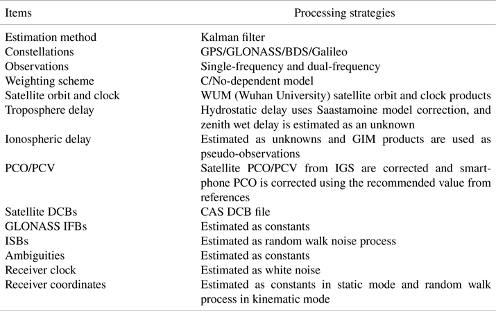
where s is the variance corresponding to each pseudorange observation (Zhang et al., Reference Zhang, Tao, Zhu, Shi and Wang2018). In this study, the coefficients a and b are set to 10 m2 and 1502 m2Hz, respectively (Kuusniemi et al., Reference Kuusniemi, Wieser, Lachapelle and Takala2007). The C/No is a real measurement with a mask value of 15 dB-Hz (Aggrey et al., Reference Aggrey, Bisnath, Naciri, Shinghal and Yang2020). When the C/No values are lower than the mask value, their corresponding observations will be missed.
The wet tropospheric delay, kinematic position coordinates and the ISBs are modelled as random walk processes, and the receiver clock offsets are estimated epoch by epoch and modelled as white noise (Zhou et al., Reference Zhou, Dong, Li, Li and Schuh2019). The satellite phase centre offset (PCO) and phase centre variation (PCV) products are acquired from the igs14.atx file provided by International GNSS Service (IGS). Since the smartphone manufacturer has not provided official receiver PCO and PCV information yet, the precise PCO and PCV data are not available. Owing to most ambiguities having no fixed characteristics, the ambiguity parameter is estimated as a constant float value (Wanninger and Heßelbarth, Reference Wanninger and Heßelbarth2020; Darugna et al., Reference Darugna, Wübbena, Wübbena, Schmitz, Schön and Warneke2021). The detailed processing strategies are provided in Table 1.
MSDQ-PPP processing strategy

3. Static experimental results and analyses
In this section, the static GNSS data collection on the smartphone is first described. Afterwards, the data reception ability and data integrity rate are analysed. Finally, the MSDQ-PPP model is evaluated in the static experiment with a comparison to different frequencies and constellation combinations.
3.1 Smartphone static GNSS data description
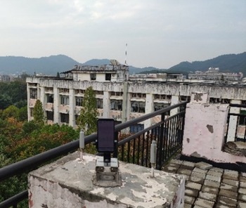
As a first released dual-frequency smartphone, the Xiaomi Mi8 smartphone is used for the static GNSS data collection. It is equipped with Broadcom's BCM47755 chip and a linearly polarised antenna. Figure 1 shows the GNSS data collection surroundings at a coordinate-known site using a Xiaomi Mi8 smartphone. The PCO correction refers to that of Netthonglang et al. (Reference Netthonglang, Thongtan and Satirapod2019) and the PCV is simply neglected. The entire experiment lasts for 160 min with a data sampling interval of 1 s. The software of GEO++ RINEX Logger in version 2.1.3 is used to convert the original data into the standard format data of RINEX 3.02 including data types of pseudorange, carrier phase, Doppler and C/No. The duty cycle mechanism is turned off to obtain consecutive carrier phase observations.
GNSS data collection on the top of Wenfa building at Central South University using a Xiaomi Mi8 smartphone

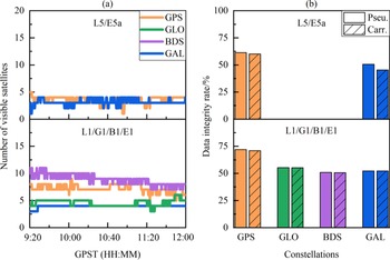
The Xiaomi Mi8 smartphone can receive GPS and Galileo L1/E1 and L5/E5a dual-frequency signals simultaneously as well as GLONASS and BDS G1/B1 single-frequency signals. Figure 2(a) provides the number of tracked satellites for each constellation and frequency. The GPS, GLONASS, BDS and Galileo satellites are tracked at average numbers of 7⋅3, 3⋅9, 9⋅7 and 4⋅7 at L1/G1/B1/E1 frequency, respectively. The numbers of the tracked GPS and BDS satellites are almost double those of the tracked GLONASS and Galileo satellites, which indicates that the GPS and BDS satellites have better tracking performance than the GLONASS and Galileo ones. At L5/E5a frequency, the GPS and Galileo satellites are tracked at average numbers of 3⋅6 and 3⋅1, which are apparently less than those at L1/E1 frequency.
Numbers of visible satellites and data integrity rates for different constellations and frequencies (‘Pseu.’ and ‘Carr.’ are the abbreviations for pseudorange and carrier phase, respectively)

To reflect the signal loss of lock or data missing rates on smartphones, the receiving capacity of the smartphone GNSS signals is evaluated by an index of data integrity rate, which is expressed by the ratio of the actual received data against the theoretical received data. The latter is calculated according to broadcast ephemeris data. Figure 2(b) shows the data integrity rate of the four constellations on L1/G1/B1/E1 and L5/E5a frequencies. Overall, the data integrity rate is in the scope of 50%–75%, which is significantly lower than the geodetic receivers that are typically at 75%–95% (Mu et al., Reference Mu, Dang and Xu2020). The GPS data integrity rate is approximately 10%–20% higher than the other constellations on both frequencies. Further, the data integrity rate of the carrier phase observations is slightly lower than that of the pseudorange observations, which is especially obvious on the L5/E5a frequency.
3.2 Positioning results and analyses
The SF-PPP technique is widely used on smartphones since most smartphones can only generate the single-frequency GNSS data. With the advent of the dual-frequency smartphones, the DF-PPP technique is applied for position determination on smartphones since it can remove the first-order ionospheric delay errors. However, even for the dual-frequency smartphones, there still exist a large number of single-frequency observations. In this section, the MSDQ-PPP is evaluated with comparisons to the SF-PPP and DF-PPP. The cutoff elevation is set to 10°. As the smartphone pseudorange and carrier phase observation noises are approximately 10 times and 5 times larger than those of geodetic receivers (Li and Geng, Reference Li and Geng2019), the pseudorange and carrier phase observation precisions are set to 3 m and 0⋅03 m, respectively. Meanwhile, the precision of the ionospheric pseudo-observations from GIM products is set to 0⋅3 m (Wang et al., Reference Wang, Bo, Yu, Li, Yin and Chen2020). Since the precision of quad-constellation GNSS observations does not differ much, the same weight ratio is assigned to different constellations.
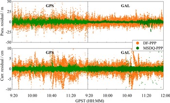
The observation residuals contain the observation noise and the other unmodelled errors, which can reflect the inner coincidence precision of the positioning model. The MSDQ-PPP and the GPS/Galileo integrated DF-PPP are processed to obtain the post-fit observation residuals, respectively. Figure 3 shows the pseudorange and the carrier phase observation residuals of GPS and Galileo for the DF-PPP and MSDQ-PPP processings. Regarding the GPS pseudorange observations, their root mean square (RMS) residuals are 8⋅5 m and 3⋅5 m for the DF-PPP and MSDQ-PPP models, respectively. For the Galileo pseudorange observations, their RMS residuals are 5⋅9 m and 1⋅4 m, respectively. In terms of the RMS statistical results, the MSDQ-PPP pseudorange observation residuals are significantly smaller than those of the DF-PPP. For the carrier phase observations, the DF-PPP exhibits RMS residuals of 2⋅4 cm and 2⋅9 cm for the GPS and Galileo whereas the corresponding MSDQ-PPP RMS residuals are only 0⋅5 cm and 0⋅6 cm. The DF-PPP carrier phase observation RMS residuals are almost five times larger than those of the MSDQ-PPP. Undoubtedly, the MSDQ-PPP model exhibits a higher inner coincidence precision than the DF-PPP model.
Pseudorange and carrier phase observation residuals for DF-PPP and MSDQ-PPP processings

The 160-minute experimental dataset is divided into four sessions, each with a session length of 40 min to ensure the PPP convergence as far as possible, especially for the SF-PPP. In each session, the Kalman filter is enforced to be re-initiated for the sake of statistical computation of the convergence time and positioning accuracy. Regarding the PPP convergence, the position filter is considered to be converged when the positioning errors reach ±1 m and keep within ±1 m. Owing to a large fluctuation in the initial 10 min, the positioning errors in the last 30 min of each session are used to calculate the RMS statistical values of positioning accuracy.
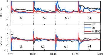
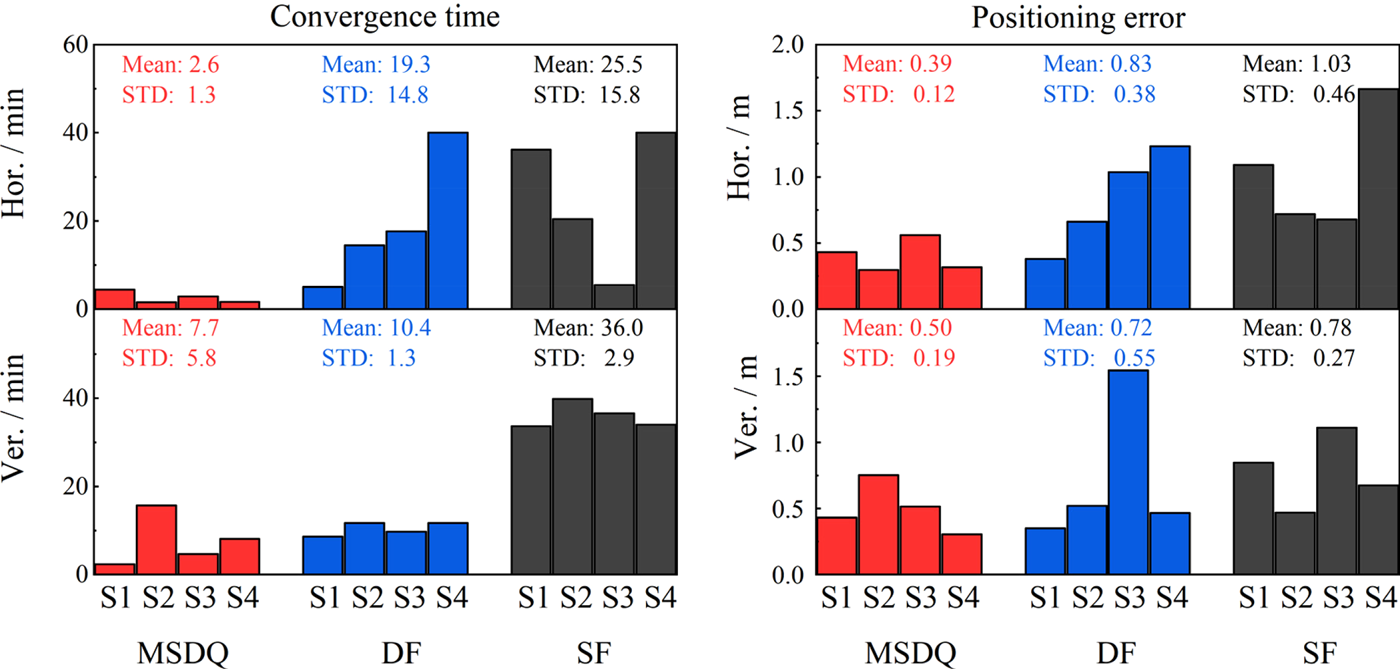
Figure 4 shows the PPP errors in the horizontal and vertical directions using the SF-PPP, DF-PPP and MSDQ-PPP models in the four different sessions. The RMS values of the positioning errors as well as their convergence times for each session are given in Figure 5. The SF-PPP solutions fluctuate significantly in the convergence process and its convergence time in the horizontal direction reaches over 30 min owing to an effect of ionospheric delay errors. By contrast, the other two PPP models converge within a few minutes in most sessions. Although the DF-PPP model uses the ionosphere-free combination to remove the first-order ionospheric error, simultaneously, the observation noise is significantly amplified. In addition, the dual-frequency observation data are insufficient. As a result, a large fluctuation is observed in the initial several epochs for the DF-PPP processing. By contrast to the DF-PPP, the MSDQ-PPP model can still shorten the convergence time to less than 10 min with an improvement rate of 90% and 79% over the SF-PPP model and 87% and 26% over the DF-PPP model in the horizontal and vertical directions, respectively. Regarding the positioning accuracy, the MSDQ-PPP RMS errors of all sessions reach 0⋅39 m and 0⋅50 m in the horizontal and vertical directions, which improves the positioning accuracy by 53% and 31% over the DF-PPP model and by 62% and 36% over the SF-PPP model, respectively.
Positioning errors in the horizontal and vertical directions using different PPP models (‘S’ denotes ‘Session’)

Statistics of convergence time and positioning errors in the horizontal and vertical directions using different PPP models

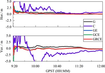
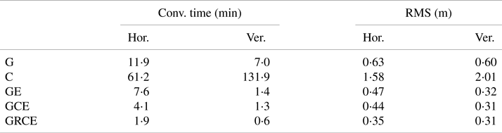
To investigate the PPP performance with different constellation combinations, observations in five different combination scenarios of BDS-only, GPS-only, GPS/Galileo, GPS/BDS/Galileo and GPS/GLONASS/BDS/Galileo are processed. The last scenario uses the MSDQ-PPP model to process the quad-constellation observations. The BDS-only scenario uses the SF-PPP model since only the single-frequency BeiDou observations are available. The other scenarios use a mixed single- and dual-frequency observation processing strategy as used in the MSDQ-PPP model. Figure 6 shows the positioning errors from different constellation combinations in the static mode. The statistical results of the convergence time and positioning errors are provided in Table 2. As only single-frequency observations are used, the BDS-only PPP solutions fluctuate substantially and their convergence time exceeds two hours in all directions. By contrast, the GPS-only PPP takes only a few minutes to converge even if the observed GPS satellites are not as many as the BDS satellites. The GPS and Galileo combination significantly improves the positioning accuracy by 25% and 47% in the horizontal and vertical directions in terms of the RMS statistics. When the BDS is further introduced, the GPS/BDS/Galileo PPP convergence time is accelerated in the horizontal direction with an improvement rate of approximately 46%. The MSDQ-PPP further improves the positioning accuracy by approximately 20% in the horizontal direction as well as the convergence time by over 50%.
PPP errors with different constellation combinations. The ‘G’, ‘C’, ‘GE’, ‘GCE’ and ‘GRCE’ in the legend denote GPS-only, BDS-only, GPS/Galileo, GPS/BDS/Galileo and GPS/GLONASS/BDS/Galileo, respectively

PPP error statistics with different constellation combinations

4. Kinematic experimental results and analyses
4.1 Smartphone kinematic GNSS data description
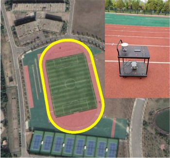
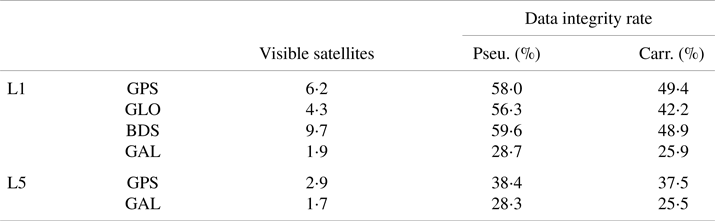
The linearly polarised antenna embedded inside smartphones is more sensitive to the observation environment. Figure 7 shows the kinematic experimental trajectory and equipment setup. A Xiaomi Mi8 smartphone is placed on a cart. In addition to the smartphone, a geodetic antenna with a Trimble NetR9 GNSS receiver is employed to serve as the benchmark value. A base station is set up at a distance of approximately 1 kilometre away from the rover station and thus the position of the geodetic receiver at the rover station can be solved by the real-time kinematic (RTK) technique. The smartphone is placed directly in front of the geodetic receiver along the heading direction and thus their relative position can be determined. The entire kinematic observation lasts approximately half an hour with a sampling rate of 1 s. Table 3 shows the statistical results of the number of visible satellites and data integrity rate to reflect the kinematic data quality at both L1/G1/B1/E1 and L5/E5a frequencies. The results show that the most BDS satellites and the least Galileo satellites can be observed according to the average number of visible satellites. More GPS and Galileo satellites can be tracked at L1/E1 frequency than at the L5/E5a frequency. Also, the data integrity rate of the GPS and Galileo is significantly decreased when compared with the static experiment. Especially for the L5/E5a signals, the data integrity rate is decreased by more than 20%. Further, the data integrity rate of the carrier phase observations is apparently lower than that of the pseudorange observations, especially for the L1/E1 frequency.
Kinematic experimental equipment setup and trajectory along the yellow line

Statistics of visible satellites and data integrity rate for different constellations in the kinematic mode

4.2 Kinematic positioning results and analyses
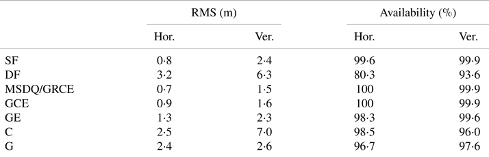
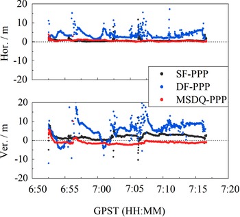
Figure 8 shows the horizontal and vertical positioning errors using the SF-PPP, DF-PPP, and MSDQ-PPP models. Their corresponding RMS statistics and the availability of the positioning solutions are presented in Table 4. The positioning solutions are considered to be available when the horizontal position errors are less than 5 m and the vertical position errors are less than 8 m.
Positioning error statistics for different PPP models and constellation combinations in kinematic mode

Positioning errors using SF-PPP, DF-PPP and MSDQ-PPP models

In contrast to the static mode, the DF-PPP positioning solutions highly fluctuate over the entire processing period owing to the unstable number of dual-frequency observations. The average number of tracked satellites at both L1 and L5 frequencies is only 4⋅6. Meanwhile, the GPS and Galileo data integrity rates at L5 frequency are below 40%, resulting in a low availability of positioning solutions at only 80⋅3%. In addition, the smartphone GNSS observations have a distinct characteristic of large observation noise. The ionosphere-free combination further amplifies the observation noise, which severely affects the positioning accuracy. By contrast, the SF-PPP solutions in the horizontal direction are more stable with an availability of over 99% owing to more usable observations. Compared with the DF-PPP and SF-PPP, the MSDQ-PPP shows the best positioning performance in terms of positioning accuracy and availability. Its availabilities of positioning solutions are 100% and 99⋅9%, and its positioning RMS errors reach 0⋅7 m and 1⋅5 m in the horizontal and vertical directions. The MSDQ-PPP improves the positioning accuracy by 78% and 76% over the DF-PPP, and by 13% and 38% over the SF-PPP in the horizontal and vertical coordinate components.
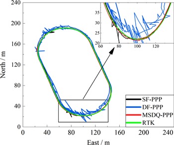
Figure 9 depicts the running trajectory in the kinematic experiment using three different positioning models. The kinematic position acquired from the geodetic receivers with the RTK technique is also displayed as a reference. The subplot in the upper right corner illustrates the positioning result differences between different PPP models in a larger scale. The trajectory from the MSDQ-PPP is shown to overlap better with the referenced trajectory, indicating an optimal positioning performance.
Kinematic trajectory using different positioning models. The origin of coordinates is located at Lat: 28°09′33.9″, Lon: 112°55′35.5″

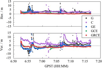
Figure 10 shows the kinematic PPP positioning errors for five different constellation combinations using the same processing strategies as used in the static mode. Their corresponding RMS statistics and availability rates are also provided in Table 4. The single-constellation PPP of GPS-only or BDS-only is observed to converge slowly with large fluctuations. The dual-constellation combination of GPS and Galileo improves the positioning accuracy by 46% and 12% in the horizontal and vertical directions over the GPS-only PPP, respectively. The triple-constellation PPP with the GPS, Galileo and BDS combination further increases the positioning accuracy by approximately 31% and 30% and the availability is also increased to almost 100%. Further, the positioning accuracy with the quad-constellation combination can still be increased but at a slight degree. Once again, the quad-constellation PPP outweighs the other constellation combinations in the kinematic mode.
PPP errors for different constellation combinations in the kinematic mode

5. Conclusions
Precise positioning on smartphones is a challenge owing to the degraded data quality. In this study, a mixed single- and dual-frequency quad-constellation GNSS precise point positioning (MSDQ-PPP) model is proposed to improve the positioning performance on smartphones by taking advantage of all available GNSS observations. The MSDQ-PPP model is fully evaluated using a Xiaomi Mi8 smartphone in both static and kinematic modes in terms of positioning accuracy, convergence time and availability of positioning solutions.
In the static mode, the statistical results of all sessions show that the MSDQ-PPP can converge to ±1 m within 10 min in most sessions. The RMSs of position errors of all sessions for the MSDQ-PPP reach 0⋅39 m and 0⋅50 m in the horizontal and vertical directions, which improves the positioning accuracy by 53% and 31% over the DF-PPP model and by 62% and 36% over the SF-PPP model. In addition, the convergence time is also significantly enhanced with an improvement rate of 90% and 79% in the horizontal and vertical directions when compared with the SF-PPP. In the kinematic mode, the MSDQ-PPP shows the best positioning performance in terms of positioning accuracy and availability of positioning solutions. The positioning RMS errors can reach 0⋅7 m and 1⋅5 m in the horizontal and vertical directions with the availability rates of 100% and 99⋅9%. The MSDQ-PPP improves the positioning accuracy by approximately 78% and 76% over the DF-PPP, and 13% and 38% over the SF-PPP in the horizontal and vertical directions, respectively. It should also be noted that all numerical results are obtained based on the Xiaomi Mi8 smartphone experimental data. More experimental tests will be made using more smartphone types in the future.
Acknowledgements
The financial support from the National Key Research and Development Program of China (Grant No. 2020YFA0713501), the National Natural Science Foundation of China (No. 42174040), the Hunan Natural Science Foundation (Grant No. 2020JJ4111), the joint teacher-student innovation and entrepreneurship project at Central South University (Grant No. 2018gczd005) and the Hunan Provincial Innovation Foundation for Postgraduate (Grant No. CX20200241) are appreciated.