1 Introduction
Recent plasma-heating experiments (Bagryansky et al.
Reference Bagryansky, Kovalenko, Savkin, Solomakhin and Yakovlev2014) in gas-dynamic traps (GDTs; Budker Institute of Nuclear Physics, Novosibirsk) (Mirnov & Ryutov Reference Mirnov and Ryutov1979; Ivanov & Prikhodko Reference Ivanov and Prikhodko2013) using high-frequency waves in the range of electron–cyclotron resonances (ECRs) have demonstrated a tangible increase in electron temperature. Moreover, it was observed that such heating is accompanied by the development of low-frequency instability. As an expected result, the ECR heating should lead to temperature anisotropy when the parallel temperature,
 $T_{\Vert h}$
(relative to confinement magnetic field
 $\boldsymbol{H}_{0}$
), is smaller than the perpendicular temperature,
 $T_{\bot h}$
, of resonant (hot) electrons.
As is well known (see e.g. Kennel & Petschek (Reference Kennel and Petschek1966), Scharer & Trivelpiece (Reference Scharer and Trivelpiece1967)), the presence of electrons with
 $T_{\Vert h}<T_{\bot h}$
in any magnetized plasmas can cause electron–cyclotron wave (ECW; also known as whistler) instability and consequently affect the transport processes (Katanuma et al.
Reference Katanuma, Kiwamoto, Ichimura, Saito and Miyoshi1990; Hojo & Hatori Reference Hojo and Hatori1993). In the scope of linear kinetic theory as applied to the plasma in a strong homogeneous magnetic field, the instability of these waves is studied in detail both analytically and with the involvement of numerical calculations in Ossakow, Haber & Ott (Reference Ossakow, Haber and Ott1972), Cuperman (Reference Cuperman1981), Garner et al. (Reference Garner, Mauel, Hokin, Post and Smatlak1990), Pritchett, Schriver & Ashour-Abdalla (Reference Pritchett, Schriver and Ashour-Abdalla1991), Gary (Reference Gary1993), Devine, Chapman & Eastwood (Reference Devine, Chapman and Eastwood1995), Gary & Wang (Reference Gary and Wang1996), Nishimura, Gary & Li (Reference Nishimura, Gary and Li2002), Gary & Karimabadi (Reference Gary and Karimabadi2006), and Lazar, Schlickeiser & Poedts (Reference Lazar, Schlickeiser and Poedts2009).
However, the geometry of the confined magnetic field in mirror devices like GDTs or GAMMA-10 (Cho et al.
Reference Cho, Kondoh, Hirata, Sakasai, Yamaguchi, Mase, Kiwamoto, Hirose, Ogura, Tanaka and Miyoshi1987; Tamano Reference Tamano1995) is generally three-dimensional, allowing two-dimensional (2D) axisymmetric approximation (see e.g. Katanuma et al. (Reference Katanuma, Kiwamoto, Ichimura, Saito and Miyoshi1990), Hojo & Hatori (Reference Hojo and Hatori1993), Nekrasov et al. (Reference Nekrasov, Grishanov, Elfimov, De Azevedo and De Assis1996), Bagulov & Kotelnikov (Reference Bagulov and Kotelnikov2012)). The most important features of any 2D systems with a minimum of confined magnetic field include the fact that the parallel velocity of plasma particles gyrating along the magnetic field lines is not constant (i.e. it is not an invariant of motion),
 $v_{\Vert }\neq \text{const}$
. Moving from the weak magnetic field to the plug (to magnetic mirrors with maximum values of the magnetic field), the parallel component of particle velocity decreases. As a result, depending on the pitch angle in the central part of the mirror device, the particle can stop and be reflected at the points where
 $v_{\Vert }=0$
. Appropriate particles are described as trapped. Particles that have no reflection points are described as untrapped. The number of such passing particles in the plasma mirror cell with a large mirror ratio is very small. Moreover, they leave the trap during one transit time, and should not impact significantly on the interaction with electromagnetic waves. For this reason, almost all the particles in the 2D mirror cell plasma can be considered trapped. As was shown in Nekrasov et al. (Reference Nekrasov, Grishanov, Elfimov, De Azevedo and De Assis1996), the conditions of the resonant interaction of waves with trapped particles in 2D systems are significantly different from the corresponding conditions in the homogeneous or helical magnetic fields,
 ${\it\omega}-{\it\Omega}_{c0}=k_{\Vert }v_{\Vert }$
. An important difference is that in a homogeneous magnetic field only one speed variable, parallel component of the particle velocity determines the magnitude of the Doppler shift in the resonance condition, while in a 2D mirror one should take into account both the cyclotron and bounce resonances (Hojo & Hatori Reference Hojo and Hatori1993; Nekrasov et al.
Reference Nekrasov, Grishanov, Elfimov, De Azevedo and De Assis1996).
To study the heating, stability problems and transport processes in 2D mirror plasma models (Katanuma et al. Reference Katanuma, Kiwamoto, Ichimura, Saito and Miyoshi1990; Hojo & Hatori Reference Hojo and Hatori1993) we should use a suitable kinetic dielectric tensor (Grishanov & Azarenkov Reference Grishanov and Azarenkov2009), accounting for the cyclotron rotation and bounce oscillations of charged particles when they interact with waves excited in the plasma. In this paper, we analyse the dispersion relations for field-aligned ECWs in two plasma models confined by means of either uniform or non-uniform mirror magnetic fields.
2 Plasma model
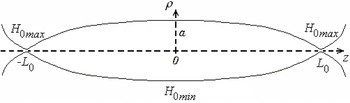
Let us consider the simple two-dimensional model of a cylindrical axisymmetric mirror-trapped plasma, where the confinement magnetic field
 $\boldsymbol{H}_{0}({\it\rho},z)=\{H_{0{\it\rho}},0,H_{0z}\}$
is oriented along the
 $z$
-axis with a minimum at the plane
 $z=0$
, see figure 1. Such mirror geometry of
 $\boldsymbol{H}_{0}$
can be created by external currents and its projections in cylindrical coordinates (
 ${\it\rho},{\it\theta},z$
) can be approximated by the expressions (Nekrasov et al.
Reference Nekrasov, Grishanov, Elfimov, De Azevedo and De Assis1996; Grishanov & Azarenkov Reference Grishanov and Azarenkov2009):
 $$\begin{eqnarray}H_{0{\it\rho}}({\it\rho},z)=\frac{-{\it\rho}z{\it\delta}H_{0\,min}}{L_{0}^{2}\left(1-{\it\delta}{\displaystyle \frac{z^{2}}{L_{0}^{2}}}\right)^{2}},\quad H_{0{\it\theta}}({\it\rho},z)=0,\quad H_{0z}({\it\rho},z)=\frac{H_{0\,min}}{1-{\it\delta}{\displaystyle \frac{z^{2}}{L_{0}^{2}}}}.\end{eqnarray}$$
Here
 $L_{0}$
is the half-length of the mirror trap along the
 $z$
-axis, so that
 $|z|\leqslant L_{0}$
;
 ${\it\delta}=(R_{m}-1)/R_{m}$
;
 $R_{m}=H_{0\,max}/H_{0\,min}$
is the mirror ratio;
 $H_{0\,min}$
is the minimal value of
 $H_{0}$
at the centre of the trap, and
 ${\it\rho}=z=0$
;
 $H_{0\,max}$
is the maximum of
 $H_{0}$
at the magnetic mirrors
 $z=\pm L_{0}$
and
 ${\it\rho}=0$
. The components of the stationary magnetic field
 $\boldsymbol{H}_{0}$
in (2.1) satisfy the Maxwell’s equation
 $\boldsymbol{{\rm\nabla}}\boldsymbol{\cdot }\boldsymbol{H}_{0}=0$
and are suitable for GDTs with a large mirror ratio,
 $R_{m}\gg 1$
.
2D straight mirror-trapped magnetic field configuration.

To simplify the analytical calculations we neglect the
 ${\it\beta}$
-effects, where the parameter
 ${\it\beta}$
is the ratio of the gas-dynamic plasma pressure to magnetic pressure and assume that the radial magnetic field is much smaller than the longitudinal one:
 $H_{0{\it\rho}}\ll H_{0z}$
. This is true for mirror traps under the condition
 $a/L_{0}\ll 1/\sqrt{R_{m}}$
, wherein
 $a$
is the radius of the plasma in the central part of the mirror (
 $z=0$
). In this case, the module containing the magnetic field module essentially depends only on the longitudinal coordinate
 $z$
:
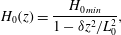 $$\begin{eqnarray}H_{0}(z)=\frac{H_{0\,min}}{1-{\it\delta}z^{2}/L_{0}^{2}},\end{eqnarray}$$
and the radius of the plasma column border along the trap varies according to the law:
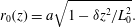 $$\begin{eqnarray}r_{0}(z)=a\sqrt{1-{\it\delta}z^{2}/L_{0}^{2}}.\end{eqnarray}$$
It should be noted that the above plasma model is similar to the so-called 2D paraxial inhomogeneous magnetic field model in Bagulov & Kotelnikov (Reference Bagulov and Kotelnikov2012) describing the ECR plasma heating in GDTs within magnetohydrodynamic theory.
In our paper, the stationary distribution function of resonant (hot,
 $h$
) electrons in velocity space is defined by the bi-Maxwellian
 $$\begin{eqnarray}F_{h}=\frac{n_{h}}{{\rm\pi}^{1.5}v_{T\Vert h}v_{T\bot h}^{2}}\exp \left\{-\frac{v^{2}}{v_{T\Vert h}^{2}}\left[1-{\it\mu}\left(1-\frac{T_{\Vert h}}{T_{\bot h}}\right)\right]\right\}.\end{eqnarray}$$
Here the variables
 $v$
(velocity vector module) and
 ${\it\mu}$
(dimensionless magnetic moment) are introduced instead of parallel
 $v_{\Vert }$
and transverse
 $v_{\bot }$
components of the plasma particle velocity through the coupling equations
 $$\begin{eqnarray}v=\sqrt{v_{\Vert }^{2}+v_{\bot }^{2}},\quad {\it\mu}=\frac{v_{\bot }^{2}}{v_{\Vert }^{2}+v_{\bot }^{2}}\left(1-{\it\delta}\frac{z^{2}}{L_{0}^{2}}\right).\end{eqnarray}$$
By means of
 $n_{h}$
we denote the density of resonance
 $h$
-electrons,
 $v_{T\Vert h}=\sqrt{2T_{\Vert h}/m_{e}}$
and
 $v_{T\bot h}=\sqrt{2T_{\bot h}/m_{e}}$
are their thermal velocity along and across
 $\boldsymbol{H}_{0}$
, and
 $m_{e}$
is the mass of the electron. As for the background (cold,
 $c$
) plasma electrons and ions, their distribution functions are simulated by the conventional Maxwell functions with low and isotropic temperature,
 $T_{\Vert c}=T_{\bot c}=T_{c}$
.
Since the stationary magnetic field is axisymmetric and has one minimum at the centre of the mirror, as noted above, all plasma particles should be separated on the untrapped and trapped particles. In our case, such separation can be done by the dimensionless parameters
 ${\it\mu}$
or
 ${\it\kappa}=\sqrt{1-{\it\mu}}$
analysing the conditions when the parallel velocity of plasma particles is equal to zero:
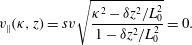 $$\begin{eqnarray}v_{\Vert }({\it\kappa},z)=sv\sqrt{\frac{{\it\kappa}^{2}-{\it\delta}z^{2}/L_{0}^{2}}{1-{\it\delta}z^{2}/L_{0}^{2}}}=0.\end{eqnarray}$$
By index
 $s=\pm 1$
here we distinguish the particles with positive and negative parallel velocities relative to
 $\boldsymbol{H}_{0}$
. The domain of the perturbed distribution functions for the trapped particles is given by the inequalities
 $$\begin{eqnarray}0\leqslant {\it\kappa}\leqslant \sqrt{{\it\delta}},\quad -z_{t}({\it\kappa})\leqslant z\leqslant z_{t}({\it\kappa}),\end{eqnarray}$$
where
 $\pm z_{t}=\pm {\it\kappa}L_{0}/\sqrt{{\it\delta}}$
are the stop points (or reflection points) of the trapped particles on the magnetic field line. As for untrapped particles, the corresponding domain of their distribution functions is defined by
 $$\begin{eqnarray}\sqrt{{\it\delta}}\leqslant {\it\kappa}\leqslant 1,\quad -L_{0}\leqslant z\leqslant L_{0}.\end{eqnarray}$$
However, the influence of untrapped (passing) particles on the wave processes in the straight mirror-trapped plasmas is not substantial, since (i) they are lost during the one transit time, and (ii) the number of passing particles
 $N_{u}$
is much smaller than the number of trapped particles
 $N_{t}$
if
 $R_{m}\gg 1$
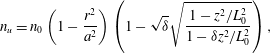
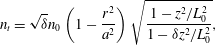
. It is easy to see that by integrating the Maxwellian distribution function of any kind of plasma particles over the corresponding phase volumes of untrapped and trapped particles, we find that the densities (concentration) of untrapped and trapped particles are equal, respectively, to
 $$\begin{eqnarray}\displaystyle & \displaystyle n_{u}=n_{0}\left(1-\frac{r^{2}}{a^{2}}\right)\left(1-\sqrt{{\it\delta}}\sqrt{\frac{1-z^{2}/L_{0}^{2}}{1-{\it\delta}z^{2}/L_{0}^{2}}}\right), & \displaystyle\end{eqnarray}$$
 $$\begin{eqnarray}\displaystyle & \displaystyle n_{t}=\sqrt{{\it\delta}}n_{0}\left(1-\frac{r^{2}}{a^{2}}\right)\sqrt{\frac{1-z^{2}/L_{0}^{2}}{1-{\it\delta}z^{2}/L_{0}^{2}}}, & \displaystyle\end{eqnarray}$$
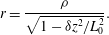
where a new radial variable
 $r$
of magnetic field line is introduced instead of
 ${\it\rho}$
by transformation
 $$\begin{eqnarray}r=\frac{{\it\rho}}{\sqrt{1-{\it\delta}z^{2}/L_{0}^{2}}}.\end{eqnarray}$$
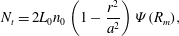
Integration of expressions (2.9) and (2.10) over the length of the mirror trap gives us the total number of each group of particles on the considered (by
 $r$
) magnetic field line:
 $$\begin{eqnarray}\displaystyle & \displaystyle N_{t}=2L_{0}n_{0}\left(1-\frac{r^{2}}{a^{2}}\right){\it\Psi}(R_{m}), & \displaystyle\end{eqnarray}$$
 $$\begin{eqnarray}\displaystyle & \displaystyle N_{u}=2L_{0}n_{0}\left(1-\frac{r^{2}}{a^{2}}\right)[1-{\it\Psi}(R_{m})], & \displaystyle\end{eqnarray}$$
where
 $$\begin{eqnarray}{\it\Psi}(R_{m})=\sqrt{\frac{R_{m}}{R_{m}-1}}\left[E(\sqrt{{\it\delta}})-\frac{1}{R_{m}}K(\sqrt{{\it\delta}})\right],\end{eqnarray}$$
and
 $K(\sqrt{{\it\delta}})$
,
 $E(\sqrt{{\it\delta}})$
are the complete elliptic integrals of the first and second kind, respectively, (3.7) and (3.8). Next it is easy to verify that in a GDT-like plasma, when
 $R_{m}\gg 1$
and
 ${\it\delta}\rightarrow 1$
, we have
 $N_{u}\ll N_{t}$
. For example, the function
 ${\it\Psi}(R_{m})$
versus the mirror ratio
 $R_{m}=20$
, 33 and 45 takes the following values:
 ${\it\Psi}(20)=0.94$
,
 ${\it\Psi}(33)=0.96$
and
 ${\it\Psi}(45)=0.97$
. Therefore, we neglect the contribution of untrapped particles to the current density components and, respectively, to the dielectric characteristics.
3 Dispersion relations of ECWs
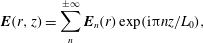
To draw an analogy with the linear theory of ECWs propagating in the plasma along the homogeneous magnetic field, it is assumed that the
 $n$
th harmonic of the transverse electric field under its Fourier decomposition over the longitudinal coordinate
 $z$
 $$\begin{eqnarray}\boldsymbol{E}(r,z)=\mathop{\sum }_{n}^{\pm \infty }\boldsymbol{E}_{n}(r)\exp (\text{i}{\rm\pi}nz/L_{0}),\end{eqnarray}$$
gives the main contribution to the
 $n$
th harmonic of the transverse current density components. In this case, i.e. when
 $E_{\Vert }=0$
,
 $H_{\Vert }=0$
, the following dispersion equation (Grishanov & Azarenkov Reference Grishanov and Azarenkov2009) can be derived from the Maxwell’s equations:
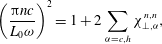 $$\begin{eqnarray}\left(\frac{{\rm\pi}nc}{L_{0}{\it\omega}}\right)^{2}=1+2\mathop{\sum }_{{\it\alpha}=c,h}{\it\chi}_{\bot ,{\it\alpha}}^{n,n},\end{eqnarray}$$
where
 ${\it\alpha}$
-indices distinguish the different particle species (e.g. cold
 ${\it\alpha}=c$
and hot
 ${\it\alpha}=h$
electrons). As usual, the contribution of protons and other heavy ions in this equation for ECWs is considered negligible.
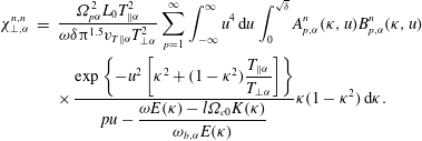
The contribution of the trapped electrons to the transverse dielectric susceptibility
 ${\it\chi}_{\bot ,{\it\alpha}}^{n,n}$
in the 2D mirror cell is determined by the summation of the bounce-resonance terms including the double integrals in velocity space with the resonant denominators and the phase coefficients:
 $$\begin{eqnarray}\displaystyle {\it\chi}_{\bot ,{\it\alpha}}^{n,n} & = & \displaystyle \frac{{\it\Omega}_{p{\it\alpha}}^{2}L_{0}T_{\Vert {\it\alpha}}^{2}}{{\it\omega}{\it\delta}{\rm\pi}^{1.5}v_{T\Vert {\it\alpha}}T_{\bot {\it\alpha}}^{2}}\mathop{\sum }_{p=1}^{\infty }\int _{-\infty }^{\infty }u^{4}\,\text{d}u\int _{0}^{\sqrt{{\it\delta}}}A_{p,{\it\alpha}}^{n}({\it\kappa},u)B_{p,{\it\alpha}}^{n}({\it\kappa},u)\nonumber\\ \displaystyle & & \displaystyle \times \,\frac{\exp \left\{-u^{2}\left[{\it\kappa}^{2}+(1-{\it\kappa}^{2}){\displaystyle \frac{T_{\Vert {\it\alpha}}}{T_{\bot {\it\alpha}}}}\right]\right\}}{pu-{\displaystyle \frac{{\it\omega}E({\it\kappa})-l{\it\Omega}_{c0}K({\it\kappa})}{{\it\omega}_{b,{\it\alpha}}E({\it\kappa})}}}{\it\kappa}(1-{\it\kappa}^{2})\,\text{d}{\it\kappa}.\end{eqnarray}$$
Here
 $$\begin{eqnarray}{\it\Omega}_{p{\it\alpha}}^{2}=\frac{4{\rm\pi}n_{{\it\alpha}}e^{2}}{m_{e}}\quad \text{and}\quad {\it\omega}_{b{\it\alpha}}({\it\kappa})=\frac{{\rm\pi}\sqrt{{\it\delta}}v_{T\Vert {\it\alpha}}}{2L_{0}E({\it\kappa})}\end{eqnarray}$$
are the squared plasma frequencies and the bounce frequencies of the trapped electrons
 $({\it\alpha}=c,h)$
, respectively, with the longitudinal thermal velocities
 $v_{T\Vert {\it\alpha}}=\sqrt{2T_{\Vert |{\it\alpha}}/m_{e}}$
;
 ${\it\Omega}_{c0}=(eH_{0\,min})/m_{e}c$
is the minimal electron–cyclotron frequency. The dependence of the phase coefficients on the speed variables is determined by expressions
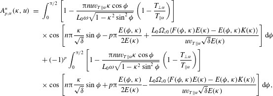 $$\begin{eqnarray}\displaystyle A_{p,{\it\alpha}}^{n}({\it\kappa},u) & = & \displaystyle \int _{0}^{{\rm\pi}/2}\left[1-\frac{{\rm\pi}nuv_{T\Vert {\it\alpha}}{\it\kappa}\cos {\it\phi}}{L_{0}{\it\omega}\sqrt{1-{\it\kappa}^{2}\sin ^{2}{\it\phi}}}\left(1-\frac{T_{\bot {\it\alpha}}}{T_{\Vert {\it\alpha}}}\right)\right]\nonumber\\ \displaystyle & & \displaystyle \times \cos \left[n{\rm\pi}\frac{{\it\kappa}}{\sqrt{{\it\delta}}}\sin {\it\phi}-p{\rm\pi}\frac{E({\it\phi},{\it\kappa})}{2E({\it\kappa})}+\frac{L_{0}{\it\Omega}_{c0}\langle F({\it\phi},{\it\kappa})E({\it\kappa})-E({\it\phi},{\it\kappa})K({\it\kappa})\rangle }{uv_{T\Vert {\it\alpha}}\sqrt{{\it\delta}}E({\it\kappa})}\right]\text{d}{\it\phi}\nonumber\\ \displaystyle & & \displaystyle +\,(-1)^{p}\int _{0}^{{\rm\pi}/2}\left[1-\frac{{\rm\pi}nuv_{T\Vert {\it\alpha}}{\it\kappa}\cos {\it\phi}}{L_{0}{\it\omega}\sqrt{1-{\it\kappa}^{2}\sin ^{2}{\it\phi}}}\left(1-\frac{T_{\bot {\it\alpha}}}{T_{\Vert {\it\alpha}}}\right)\right]\nonumber\\ \displaystyle & & \displaystyle \times \cos \left[n{\rm\pi}\frac{{\it\kappa}}{\sqrt{{\it\delta}}}\sin {\it\phi}+p{\rm\pi}\frac{E({\it\phi},{\it\kappa})}{2E({\it\kappa})}-\frac{L_{0}{\it\Omega}_{c0}\langle F({\it\phi},{\it\kappa})E({\it\kappa})-E({\it\phi},{\it\kappa})K({\it\kappa})\rangle }{uv_{T\Vert {\it\alpha}}\sqrt{{\it\delta}}E({\it\kappa})}\right]\text{d}{\it\phi},\nonumber\\ \displaystyle & & \displaystyle\end{eqnarray}$$
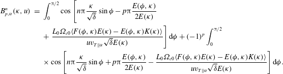 $$\begin{eqnarray}\displaystyle B_{p,{\it\alpha}}^{n}({\it\kappa},u) & = & \displaystyle \int _{0}^{{\rm\pi}/2}\cos \left[\vphantom{\frac{{\it\Omega}_{c0}{\it\varphi}}{v_{T\Vert {\it\alpha}}\sqrt{{\it\delta}}}}n{\rm\pi}\frac{{\it\kappa}}{\sqrt{{\it\delta}}}\sin {\it\phi}-p{\rm\pi}\frac{E({\it\phi},{\it\kappa})}{2E({\it\kappa})}\right.\nonumber\\ \displaystyle & & \displaystyle +\left.\frac{L_{0}{\it\Omega}_{c0}\langle F({\it\phi},{\it\kappa})E({\it\kappa})-E({\it\phi},{\it\kappa})K({\it\kappa})\rangle }{uv_{T\Vert {\it\alpha}}\sqrt{{\it\delta}}E({\it\kappa})}\right]\text{d}{\it\phi}+(-1)^{p}\int _{0}^{{\rm\pi}/2}\nonumber\\ \displaystyle & & \displaystyle \times \cos \left[n{\rm\pi}\frac{{\it\kappa}}{\sqrt{{\it\delta}}}\sin {\it\phi}+p{\rm\pi}\frac{E({\it\phi},{\it\kappa})}{2E({\it\kappa})}-\frac{L_{0}{\it\Omega}_{c0}\langle F({\it\phi},{\it\kappa})E({\it\kappa})-E({\it\phi},{\it\kappa})K({\it\kappa})\rangle }{uv_{T\Vert {\it\alpha}}\sqrt{{\it\delta}}E({\it\kappa})}\right]\text{d}{\it\phi}.\nonumber\\ \displaystyle & & \displaystyle\end{eqnarray}$$
The functions
 $$\begin{eqnarray}K({\it\kappa})=\int _{0}^{{\rm\pi}/2}\frac{\text{d}{\it\varphi}}{\sqrt{1-{\it\kappa}^{2}\sin ^{2}{\it\varphi}}},\quad F({\it\phi},{\it\kappa})=\int _{0}^{{\it\phi}}\frac{\text{d}{\it\varphi}}{\sqrt{1-{\it\kappa}^{2}\sin ^{2}{\it\varphi}}}\end{eqnarray}$$
and
 $$\begin{eqnarray}E({\it\kappa})=\int _{0}^{{\rm\pi}/2}\sqrt{1-{\it\kappa}^{2}\sin ^{2}{\it\varphi}}\,\text{d}{\it\varphi},\quad E({\it\phi},{\it\kappa})=\int _{0}^{{\it\phi}}\sqrt{1-{\it\kappa}^{2}\sin ^{2}{\it\varphi}}\,\text{d}{\it\varphi}\end{eqnarray}$$
correspond to complete and incomplete elliptic integrals of the first and second kind, respectively.
The vanishing of the denominator in
 ${\it\chi}_{\bot ,{\it\alpha}}^{n,n}$
determines the condition of the resonant interaction of ECWs with the trapped electrons in the plasma mirror cell
 $$\begin{eqnarray}{\it\omega}-{\it\Omega}_{c0}\frac{K({\it\kappa})}{E({\it\kappa})}=\frac{p{\rm\pi}v\sqrt{{\it\delta}}}{2L_{0}E({\it\kappa})},\quad p=0,\pm 1,\pm 2,\ldots ,\end{eqnarray}$$
where the wave frequency, the bounce-averaged cyclotron frequency and the bounce frequency of electrons are interconnected; and the integer
 $p$
designates the number of possible bounce resonances. The trapped electrons (both cold and hot) with appropriate speed parameters in (3.9) are described as resonant. These electrons are responsible for the wave damping or the growth rate of the wave amplitude at the equilibrium or non-equilibrium plasma models, respectively. Moving along the stationary magnetic field lines the resonant trapped particles bounce and oscillate between the reflection (or stop) points and are able to interact with the wave in two zones of the cyclotron resonance, which are symmetrical with respect to the equatorial plane between the magnetic mirrors.
Further, the dispersion equation (3.2) should be resolved numerically with respect to the real and imaginary parts of the wave frequency,
 ${\it\omega}=\text{Re}\,{\it\omega}+\text{i}\,\text{Im}\,{\it\omega}$
, to determine the excitation conditions of the unstable ECWs in the plasma. As usual, the increment (decrement) of these waves is determined by the contribution of the resonant electrons to the imaginary part of the dielectric susceptibility
 $\text{Im}\,{\it\chi}_{\bot ,h}^{n,n}$
, which can be calculated directly from
 ${\it\chi}_{\bot ,{\it\alpha}}^{n,n}$
using the well-known residue (or Landau rule) method:
 $\text{Im}\,{\it\chi}_{\bot ,h}^{n,n}=\sum _{p=1}^{\infty }\text{Im}\,{\it\chi}_{\bot ,p,h}^{n,n}$
where
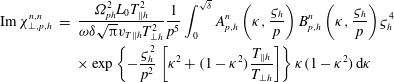 $$\begin{eqnarray}\displaystyle \text{Im}\,{\it\chi}_{\bot ,p,h}^{n,n} & = & \displaystyle \frac{{\it\Omega}_{ph}^{2}L_{0}T_{\Vert h}^{2}}{{\it\omega}{\it\delta}\sqrt{{\rm\pi}}v_{T\Vert h}T_{\bot h}^{2}}\frac{1}{p^{5}}\int _{0}^{\sqrt{{\it\delta}}}A_{p,h}^{n}\left({\it\kappa},\frac{{\it\varsigma}_{h}}{p}\right)B_{p,h}^{n}\left({\it\kappa},\frac{{\it\varsigma}_{h}}{p}\right){\it\varsigma}_{h}^{4}\nonumber\\ \displaystyle & & \displaystyle \times \exp \left\{-\frac{{\it\varsigma}_{h}^{2}}{p^{2}}\left[{\it\kappa}^{2}+(1-{\it\kappa}^{2})\frac{T_{\Vert h}}{T_{\bot h}}\right]\right\}{\it\kappa}(1-{\it\kappa}^{2})\,\text{d}{\it\kappa}\end{eqnarray}$$
describes the partial contribution of individual bounce-resonant terms into
 $\text{Im}\,{\it\chi}_{\bot ,h}^{n,n}$
. Here
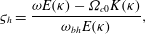 $$\begin{eqnarray}{\it\varsigma}_{h}=\frac{{\it\omega}E({\it\kappa})-{\it\Omega}_{c0}K({\it\kappa})}{{\it\omega}_{bh}E({\it\kappa})},\end{eqnarray}$$
so that the conditions of the resonant wave–particle interaction for energetic
 $h$
-electrons can be rewritten as
 $pu={\it\varsigma}_{h}$
, where
 $u=v/v_{T\Vert h}$
.
The transverse dielectric susceptibility in a magnetized plasma for the ECWs propagating along a homogeneous magnetic field has a well-known form (see e.g. Gary (Reference Gary1993))
 $$\begin{eqnarray}{\it\chi}_{\bot ,{\it\alpha}}=\frac{{\it\Omega}_{p{\it\alpha}}^{2}}{2{\it\omega}^{2}}\left[\frac{T_{\bot {\it\alpha}}}{T_{\Vert {\it\alpha}}}-1+\left(\frac{T_{\bot {\it\alpha}}}{T_{\Vert {\it\alpha}}}-1\right)\frac{{\it\omega}-{\it\Omega}_{c0}}{k_{\Vert }v_{T\Vert {\it\alpha}}}Z\left(\frac{{\it\omega}-{\it\Omega}_{c0}}{k_{\Vert }v_{T\Vert {\it\alpha}}}\right)+\frac{{\it\omega}}{k_{\Vert }v_{T\Vert {\it\alpha}}}Z\left(\frac{{\it\omega}-{\it\Omega}_{c0}}{k_{\Vert }v_{T\Vert {\it\alpha}}}\right)\right],\end{eqnarray}$$
where
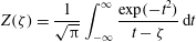 $$\begin{eqnarray}Z({\it\zeta})=\frac{1}{\sqrt{{\rm\pi}}}\int _{-\infty }^{\infty }\frac{\exp (-t^{2})}{t-{\it\zeta}}\,\text{d}t\end{eqnarray}$$
is the so-called plasma-dispersion function.
As a result, the dispersion equation of ECWs in a magnetized plasma, confined by a uniform magnetic field, can be written as
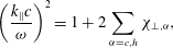 $$\begin{eqnarray}\left(\frac{k_{\Vert }c}{{\it\omega}}\right)^{2}=1+2\mathop{\sum }_{{\it\alpha}=c,h}{\it\chi}_{\bot ,{\it\alpha}},\end{eqnarray}$$
where the parallel wave number
 $k_{\Vert }$
is connected with the eigenmode numbers
 $n$
as
 $k_{\Vert }=n{\rm\pi}/L_{0}$
. In this case, the squared refractive index of ECWs is given by
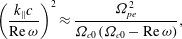 $$\begin{eqnarray}\left(\frac{k_{\Vert }c}{\text{Re}\,{\it\omega}}\right)^{2}\approx \frac{{\it\Omega}_{pe}^{2}}{{\it\Omega}_{c0}({\it\Omega}_{c0}-\text{Re}\,{\it\omega})},\end{eqnarray}$$
where
 ${\it\Omega}_{pe}^{2}=4{\rm\pi}n_{e}e^{2}/m_{e}$
is the squared electron plasma frequency calculated by the sum density of cold
 $(n_{c})$
and hot
 $(n_{h})$
electrons,
 $n_{e}=n_{c}+n_{h}$
. Analysing the expression (3.15) under the condition
 $(k_{\Vert }c/\text{Re}\,{\it\omega})^{2}>0$
, one can see that the propagation of ECWs is possible only in the frequency range below the electron–cyclotron frequency:
 $\text{Re}\,{\it\omega}<{\it\Omega}_{c0}$
.
Another important characteristic of the ECWs is the imaginary part of their frequency,
 ${\it\gamma}=\text{Im}\,{\it\omega}$
, which characterizes the growth rate of the waves (if
 ${\it\gamma}>0$
) or their decrement (if
 ${\it\gamma}<0$
). The increment (decrement) of ECWs,
 ${\it\gamma}_{1D}$
, in a well-studied case of uniform magnetic field, if
 $\text{Im}\,{\it\omega}\ll \text{Re}\,{\it\omega}$
, in our notation can be expressed as
 $$\begin{eqnarray}\frac{{\it\gamma}_{1D}}{{\it\Omega}_{c0}}\approx -2\frac{\text{Re}\,{\it\omega}({\it\Omega}_{c0}-\text{Re}\,{\it\omega})^{2}}{{\it\Omega}_{pe}^{2}(2{\it\Omega}_{c0}-\text{Re}\,{\it\omega})}\,\text{Im}\,{\it\chi}_{\bot ,h},\end{eqnarray}$$
where
 $$\begin{eqnarray}\text{Im}\,{\it\chi}_{\bot ,h}=\frac{{\it\Omega}_{ph}^{2}{\it\Omega}_{c0}\sqrt{{\rm\pi}}}{2(\text{Re}\,{\it\omega})^{2}k_{\Vert }v_{T\Vert h}}\left[\frac{\text{Re}\,{\it\omega}}{{\it\Omega}_{c0}}-\left(1-\frac{\text{Re}\,{\it\omega}}{{\it\Omega}_{c0}}\right)\left(\frac{T_{\bot h}}{T_{\Vert h}}-1\right)\right]\exp \left[-\left(\frac{\text{Re}\,{\it\omega}-{\it\Omega}_{c0}}{k_{\Vert }v_{T\Vert h}}\right)^{2}\right]\end{eqnarray}$$
describes the contribution of resonant electrons into the transverse susceptibility for the right-hand polarized ECWs. Using these expressions, one can see that the instability of ECWs is possible if
 $\text{Im}\,{\it\chi}_{\bot ,h}<0$
. As is well known, this condition occurs only in plasma with anisotropic temperature when
 $T_{\bot h}>T_{\Vert h}$
.
4 Numerical results
In this section, we compare the growth rates of electron–cyclotron waves in plasma systems, confined by the uniform,
 ${\it\gamma}_{1D}$
, and mirror,
 ${\it\gamma}_{2D}$
, magnetic field configurations. In our calculations, according to Bagryansky et al. (Reference Bagryansky, Kovalenko, Savkin, Solomakhin and Yakovlev2014), the following plasma-field parameters are suitable for GDTs:
 $L_{0}=350$
cm,
 $H_{0\,min}=0.35$
T,
 $R_{m}=33$
,
 $a=14$
cm,
 $n_{c}=2\times 10^{13}~\text{cm}^{-3}$
and
 $n_{h}=0.4\times 10^{13}~\text{cm}^{-3}$
. The longitudinal and transverse temperature of resonant (high-energy) electrons are assumed equal to
 $T_{\Vert h}=10$
keV and
 $T_{\bot h}=40$
keV, respectively, while the temperature of the cold (background) particles is considered to be low and isotropic. Unfortunately, we have no data on the level of electron temperature anisotropy in GDT. But according to the first experiments on ECR plasma heating in GAMMA-10 (Cho et al.
Reference Cho, Kondoh, Hirata, Sakasai, Yamaguchi, Mase, Kiwamoto, Hirose, Ogura, Tanaka and Miyoshi1987), the temperature anisotropy of resonant (hot) electrons on the level was observed to be about
 $T_{\bot h}/T_{\Vert h}\sim 5$
under the averaged temperature in the range 50–60 keV. So our parameters for numerical calculations can be considered quite realistic. Of course, our analytical expressions and algorithms are acceptable for calculations under other values of temperature anisotropy and levels of
 $T_{\Vert h}$
and
 $T_{\bot h}$
.
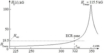
The structure of the stationary magnetic field on the right-hand side of the mirror cell is shown in figure 2. This model is in good agreement with a 2D plasma model used in Bagulov & Kotelnikov (Reference Bagulov and Kotelnikov2012) when studying the MHD conditions of ECR plasma heating in a GDT device. The dotted line corresponds to the strength of the external magnetic field at the points of the ECRs,
 $z=\pm z_{res}$
, where the electron–cyclotron frequency coincides with the gyrotron frequency
 $f=54.5$
GHz. In this case, according to (2.2),
 $z_{res}=322$
cm. On the other hand, the zones of ECR,
 $\pm z_{res}$
, are the stop (reflection, rotation) points for the resonant trapped electrons interacting with the pump ECWs by means of cyclotron and bounce resonances.
On-axis magnetic field structure
 $H_{0}(z)$
in the plasma mirror cell.

As a result, the longitudinal eigenmode number
 $n$
of ECWs can be estimated by the expression
 $$\begin{eqnarray}n({\it\omega})\approx \frac{L_{0}{\it\Omega}_{pe}\,\text{Re}\,{\it\omega}}{{\rm\pi}c\sqrt{{\it\Omega}_{c0}({\it\Omega}_{c0}-\text{ R e }\,{\it\omega})}}.\end{eqnarray}$$
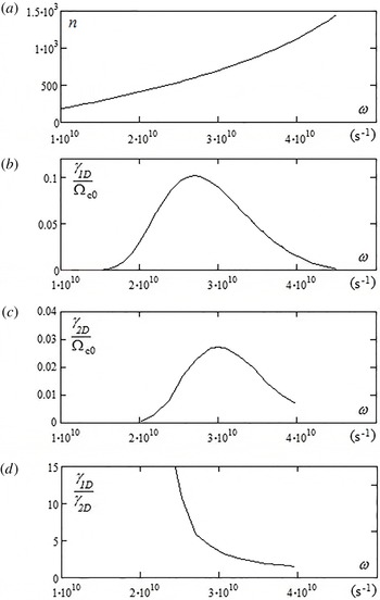
The corresponding dependence
 $n({\it\omega})$
versus
 ${\it\omega}$
(equal
 $\text{Re}\,{\it\omega}$
) is plotted in figure 3(a). The growth rate of ECWs in the straight magnetic field,
 ${\it\gamma}_{1D}$
, is shown in figure 3(b).
As for the GDT-like plasma, the temporal growth rate there can be estimated by
 $$\begin{eqnarray}\frac{{\it\gamma}_{2D}}{{\it\Omega}_{c0}}\approx -2\frac{\text{Re}\,{\it\omega}({\it\Omega}_{c0}-\text{Re}\,{\it\omega})^{2}}{{\it\Omega}_{pe}^{2}(2{\it\Omega}_{c0}-\text{Re}\,{\it\omega})}\,\text{Im}\,{\it\chi}_{\bot ,h}^{n,n}.\end{eqnarray}$$
The dependence of
 ${\it\gamma}_{2D}/{\it\Omega}_{c0}$
versus
 ${\it\omega}(=\text{Re}\,{\it\omega})$
for ECW instability is present in figure 3(c) for waves in GDT-like plasma. The computations of
 ${\it\gamma}_{2D}$
are carried out in the interval
 $2\times 10^{10}~\text{s}^{-1}\leqslant {\it\omega}\leqslant 4\times 10^{10}~\text{s}^{-1}$
, whereas the minimal and maximal electron gyrofrequencies are equal, respectively, to
 ${\it\Omega}_{c0}\approx 6.15\times 10^{10}~\text{s}^{-1}$
and
 ${\it\Omega}_{c0\,max}\approx 2\times 10^{12}~\text{s}^{-1}$
; the angular gyrotron frequency is
 ${\it\Omega}_{f}=2{\rm\pi}f=3.42\times 10^{11}~\text{s}^{-1}$
. As shown in figure 3(b) and (c), instability of ECWs is possible for both plasma models in the frequency range
 ${\it\omega}<{\it\Omega}_{c0}$
and is impossible if
 ${\it\Omega}_{c0}<{\it\omega}<{\it\Omega}_{c0\,max}$
.
The dispersion characteristics of ECWs versus in the GDT-like plasma: (a) longitudinal eigenmode numbers n of ECWs versus
 ${\it\omega}$
, (b) growth rate of ECWs
 ${\it\gamma}_{1D}/{\it\Omega}_{c0}$
in the uniform magnetic field, (c) growth rate of ECWs
 ${\it\gamma}_{2D}/{\it\Omega}_{c0}$
in the mirror-trapped plasma, (d) the ratio
 ${\it\gamma}_{1D}/{\it\gamma}_{2D}$
of ECWs versus
 ${\it\omega}$
.

As one can see, the dependencies
 ${\it\gamma}_{1D}$
and
 ${\it\gamma}_{2D}$
on
 ${\it\omega}$
are similar (for the same bulk parameters). The ratio
 ${\it\gamma}_{1D}/{\it\gamma}_{2D}\propto 2/100$
versus
 ${\it\omega}$
for the considered models is present in figure 3(d). This dependence is nonlinear; the difference is very large (factor 100) for waves in the low-frequency range
 ${\it\omega}\sim 2\times 10^{10}~\text{s}^{-1}$
and is smaller (factor 2) at the high frequencies
 ${\it\omega}\sim 4\times 10^{10}~\text{s}^{-1}$
.
The large difference between
 ${\it\gamma}_{1D}$
and
 ${\it\gamma}_{2D}$
is connected with the fact that the wave–particle interaction in the straight magnetic field plasma is more effective since the resonant particles move gyrating along the uniform magnetic field line with a constant parallel velocity and interact permanently (in time) with the wave due to the cyclotron phase resonances. As for mirror-trapped plasmas, since
 $v_{\Vert }\neq \text{const.}$
for the trapped particles, there is another wave–particle resonance condition involving the particle energy, the pitch angle, the wave frequency, the cyclotron and bounce resonances. As a result, the resonant trapped electrons bouncing between the mirror points only part of the bounce time can interact effectively with the right-hand polarized wave at the ECR zones. Moreover, depending on the pitch angle in the central part of the mirror cell some electrons, in principle, are not capable of reaching the ECR zones, which are located at the mirror areas of the trap.
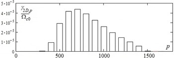
It should be noted that each point on figure 3(c) is a result of adding a large number of bounce-resonant terms:
 $$\begin{eqnarray}\frac{{\it\gamma}_{2D}}{{\it\Omega}_{c0}}\approx -2\frac{\text{Re}\,{\it\omega}({\it\Omega}_{c0}-\text{Re}\,{\it\omega})^{2}}{{\it\Omega}_{pe}^{2}(2{\it\Omega}_{c0}-\text{Re}\,{\it\omega})}\mathop{\sum }_{p=1}^{\infty }\,\text{Im}\,{\it\chi}_{\bot ,p,h}^{n,n}=\mathop{\sum }_{p=1}^{\infty }\frac{{\it\gamma}_{2D,p}}{{\it\Omega}_{c0}}.\end{eqnarray}$$
A typical structure of the individual bounce-resonant terms,
 ${\it\gamma}_{2D,p}/{\it\Omega}_{c0}$
, providing the main contribution to the maximal growth rate of ECW instability in the plasma mirror cell under
 ${\it\omega}\sim 3\times 10^{10}~\text{s}^{-1}$
, is shown in figure 4. Since the bounce frequency of resonant electrons at the given parameters
 $L_{0}=350$
cm and
 $T_{\Vert h}=10$
keV is three orders of magnitude lower than the wave frequency
 ${\it\omega}$
and the minimal electron–cyclotron frequency
 ${\it\Omega}_{c0}$
, the principal terms in (4.3) are the bounce-resonance numbers in the range
 $400<p<1500$
.
Structure of the bounce-resonance terms that determine the maximal instability growth rate of ECWs in the plasma mirror cell.

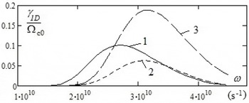
Of course, the growth rate of ECWs in GDT-like plasma should substantially depend on the plasma temperature and, in particular, on the ratio
 $T_{\bot h}/T_{\Vert h}$
. The corresponding results for waves in the straight magnetic field have been present in figure 5 for different temperatures of resonant electrons.
The growth rates versus
 ${\it\omega}$
of ECWs for different temperatures of resonant electrons: (1)
 $T_{\Vert h}=10~\text{keV}$
,
 $T_{\bot h}=40~\text{keV}$
; (2)
 $T_{\Vert h}=5~\text{keV}$
,
 $T_{\bot h}=20~\text{keV}$
; (3)
 $T_{\Vert h}=5~\text{keV}$
,
 $T_{\bot h}=40~\text{keV}$
.

Curve 1 has been calculated for plasma where the parallel and perpendicular temperatures are equal to
 $T_{\Vert h}=10$
keV and
 $T_{\bot h}=40$
keV. Curves 2 and 3 show the dependence
 ${\it\gamma}_{1D}/{\it\Omega}_{c0}$
versus
 ${\it\omega}$
for lower parallel temperature:
 $T_{\Vert h}=5$
keV, under different perpendicular temperatures:
 $T_{\bot h}=20$
keV and
 $T_{\bot h}=40$
keV, respectively. As one can see, according these plots, the maximal values of the ECW growth rate depend substantially on the ratio
 $T_{\bot h}/T_{\Vert h}$
, whereas these maxima in plasma with a high parallel temperature are achieved in the low-frequency range.
5 Conclusion
In conclusion, let us discuss the main features of the kinetic theory of field-aligned ECWs in collisionless magnetized axisymmetric mirror cell plasma (i.e. in cylindrical open traps with magnetic mirrors).
As for the plasma models in the direct magnetic field, all the information about wave–particle interactions in mirror devices is contained in the components of the dielectric permittivity or susceptibility tensors. To develop the kinetic theory of ECWs in the mirror-trapped plasma, specific expressions for the transverse dielectric susceptibility elements, which are involved in the corresponding dispersion equation, are necessary.
Since in the plasma mirror cell with a large mirror ratio, most of the plasma particles are trapped (oscillating between the magnetic mirrors), when describing the resonant wave–particle interaction there we should take into account both the cyclotron and bounce resonances. As a result, the conditions of the wave–particle phase resonances in the plasma mirror cell and in the straight uniform magnetic field are entirely different. As usual, the contribution of the resonant trapped electrons to the imaginary (anti-hermitian) of the transverse dielectric susceptibility determines the magnitude of the growth increments (damping decrements) of ECWs in the collisionless limit.
ECWs are always damped in thermodynamic equilibrium plasmas with an isotropic electron temperature (i.e. with the Maxwellian distribution function) under all containing magnetic field configurations. It is shown that the instability of these waves is possible only in a non-equilibrium plasma with anisotropic electron temperature, i.e. with a bi-Maxwellian steady-state particle distribution function, when
 $T_{\Vert h}<T_{\bot h}$
. The resonant electrons with such temperatures should appear in the plasma during its ECR heating. The instability of ECWs occurs in the plasma mirror cell only in the frequency range below the minimum electron–cyclotron frequency, which is usually much lower than the gyrotron frequency used for the RF power input into the plasma volume at the ECR heating.
An important feature of ECWs is that their maximal growth rates in mirror devices are many times smaller than the corresponding increments in a magnetized plasma confined by a homogeneous magnetic field, under the same background plasma-field parameters. Moreover, the growth rates of ECWs depend substantially on the levels of the longitudinal and transverse temperatures of the resonant (hot,
 $h$
) electrons. As longitudinal temperature
 $T_{\Vert h}$
increases, the maximal increment of ECWs is shifted to the range of lower frequencies, and the value of the growth rate increases linearly (proportionally) with respect to
 $T_{\bot h}/T_{\Vert h}$
. As an application of our results for the cited GDT experiments, we see that, according to figures 3 and 5, the maximal growth rate of whistler instability in the GDT plasma should be detected at the frequency range of approximately
 $3\times 10^{10}~\text{s}^{-1}$
(or
 $4.8\times 10^{10}$
Hz).
When analysing the problems of the excitation of the waves and their stability or instability in the mirror-trapped plasma it should be taken into account that there, in contrast to the case of a uniform magnetic field, the right-hand polarized (electron–cyclotron) and left-hand polarized (ion–cyclotron) waves are interconnected. This means that the development of instability of the ECWs in the mirror plasma must be accompanied by the excitation of ion–cyclotron waves. In turn, the collisionless dissipation of these waves on the resonant ions should lead to a corresponding heating of plasma ions.
In this paper we have developed a kinetic theory of instability of field-aligned ECWs (propagating along the stationary magnetic field
 $\boldsymbol{H}_{0}$
). To investigate the dispersion characteristics of these waves at their ‘oblique’ propagation with respect to the confined magnetic field, it is necessary to know the dielectric permittivity tensor for the electromagnetic waves with non-zero radial eigenmode numbers in a mirror plasma, taking into account the finite Larmor radius effects of plasma particles. However, in the literature there are no data on the contribution of the resonant particles into the dielectric tensor components in such an approximation, which opens avenues for further research in this direction.
For some technical reasons, the first ECR experiments on heating the GDT plasma (Bagryansky et al.
Reference Bagryansky, Kovalenko, Savkin, Solomakhin and Yakovlev2014) were carried out using only one of the gyrotron modules. The second gyrotron will be applied after a magnetic field reconfiguration of the other end mirror of the machine. At this stage it is unclear how to choose the pump frequency and power for the second gyrotron. The increase of plasma temperature during ECR heating should lead to an increase of gas-dynamic pressure and, consequently, to a decrease in the stationary magnetic field. Therefore, as an alternative to gyrotrons of the same frequency it may be preferable for the second microwave generator to have a lower frequency,
 $f_{2}=f_{1}/{\it\sigma}$
, where the factor
 ${\it\sigma}\sim 1.3{-}1.5$
accounts for the diamagnetism of the plasma. In this case, the ECR zones for two gyrotron frequencies,
 $f_{1}$
and
 $f_{2}$
, will overlap, to allow efficient heating of the resonant electrons during microwave radiation, by taking account of the reconstruction of the lower confined magnetic field. However, this problem is very complicated and needs experimental predictions and additional investigation.