I. INTRODUCTION
With extremely high elastic modulus, super strength, outstanding thermal, and electrical properties, carbon nanotubes (CNTs) are considered as one of the most potential reinforcements for composites since it was found by Iijima in 1991.Reference Zhan, Kuntz, Wan and Mukherjee1,Reference Iijima, Brabec, Maiti and Bernholc2 Up to now, researchers have done a great amount of work on CNT-reinforced composites. Among them, great success had been acquired mainly on CNT-reinforced polymer composites,Reference Selvamani, Premkumar, Vigneshwar, Hariprasath and Palanikumar3–Reference Banerjee, Nguyen and Chuang7 in which CNTs realized uniform distribution in the matrix even with big volume fraction of CNT addition. As for CNT-reinforced metal matrix composites (MMCs/CNTs), researchers are now facing a few challenges which prevent them from further improving the mechanical properties of the compositesReference Liu, Ke, Liu, Huang and Li8–Reference Wu, Wu, Deng, Nie, Wang, Hu and Zheng10: (i) uniform distribution of CNTs in the composites; (ii) strong interfacial bonding between CNTs and the matrix. Normally, because of their nanoscale, it is really difficult to obtain uniform distribution of CNTs in the metal matrix because CNTs are prone to agglomerate with each other by strong Van den Waals force. Although some researchers have tried many methods to disperse CNTs in the composites, large clusters of CNTs formed in the composites once the CNT contents exceeded 2%,Reference Kwon, Takamichi, Kawasaki and Leparoux14 which limits the reinforcing potential of CNTs in MMCs. Furthermore, strong interface bonding is hard to be obtained due to the poor affinity of CNTs with metal matrix. The strong interface bonding is essential to effective load transfer between the matrix and the reinforcements, which significantly affects the strengthening efficiency of CNTs.
In recent years, for CNT-reinforced MMCs, Al, Cu, and Ti are normally used as the matrix.Reference Cha, Kim, Arshad, Mo and Hong11,Reference Jiang, Fan, Li, Kai, Zhang, Chen, Humphries, Heness and Yeung12 Specifically, for Al/CNT composites, several methods have already succeeded in fabricating composites with uniform CNT distribution. Among these fabrication methods, powder metallurgy was the most commonly used method by which CNTs could distribute homogeneously in the composites even when the volume fraction of CNT reached 5%.Reference Singla, Amulya and Murtaza13 However, high energy ball-milling during the first step of this fabrication process could cause great damage to the morphology structure of the CNT. Furthermore, CNTs would react with the Al matrix to produce Al4C3 during the sintering process, which would undermine the structure of the CNT as well. Furthermore, as a brittle phase, a big fraction of Al4C3 would also show a negative impact on the mechanical performance of the composites.Reference Kwon, Takamichi, Kawasaki and Leparoux14
As for CNT-reinforced magnesium matrix composites, less work has been done because magnesium is too chemically active to proceed ball milling, so a novel method has to be taken to introduce CNTs into the Mg matrix.Reference Wang, Xu, Wu, Chen, Peng, Jin, Xin, Zhang, Liu, Chen, Chen, Deng and Wang15,Reference Shi, Wang, Zhang, Li, Ding and Wu16 Fortunately, CNTs are chemically compatible with Mg melt. Namely, the melt spinning process can be picked to fabricate Mg/CNT composites while without any chemical production. However, before CNTs were introduced into the Mg matrix, a predispersion process was indispensable to promote the dispersion of CNTs in the composite.
To further increase the performance of materials, hybrid reinforcements were used by researchers to obtain higher strengthening efficiency.Reference Shen, Wang, Zhang, Zheng and Wu17–Reference Chuc, Thanh, Tu, Phuong, Thang and Tam21 For hybrid reinforcements, a variety of strengthening materials were picked for different origins. Some hybrid reinforcements were used to reach a uniform dispersion of strengthening materials in the composites.Reference Akbarpour, Salahi, Hesari, Simchi and Kim22,Reference Alizadeh, Abdollahi and Biukani23 Generally, hybrid reinforcements are used to obtain a better predispersion effect so as to promote the final reinforcement distribution. Furthermore, sometimes, one kind of reinforcement is used only as the carrier for the major reinforcement.Reference Li, Su, Ouyang and Zhang24 The reinforcing materials which are hard to disperse uniformly in the matrix may get improved distribution through this way. Besides, hybrid reinforcements may form a new structure in the composite through reinforcement architecture, which can result in a good synergetic strengthening effect.Reference Lachman, Wiesel, Villoria, Wardle and Wagner25,Reference Li, Fan, Guo, Li, Su and Zhang26
For microsized reinforcements, the strengthening efficiency is low and plasticity of the composites sacrificed with increasing reinforcement proportion.Reference Nie, Wang, Wu, Hu, Zheng and Xu27–Reference Chen, Chen, Han, Xia and Wu29 On the contrary, mechanical properties of composites reinforced by a small fraction of nanosized reinforcements get significant improvement with negligible ductility sacrifice. Although nanoparticles have potential to improve the strength of the matrix metal and even enhance the plasticity simultaneously, they are difficult to disperse uniformly in the metal matrix. Small progress had been acquired until a recent research study by Chen et al.,Reference Chen, Xu, Choi, Pozuelo, Ma, Bhowmick, Yang, Mathaudhu and Li30 in which uniformly dispersed silicon carbide nanoparticle-reinforced magnesium composites with a high volume fraction of the nanofiller were fabricated. Enhancement of strength, stiffness, plasticity, and high-temperature stability were simultaneously achieved, delivering a higher specific yield strength and higher specific modulus than almost all structural metals.
In the present work, multiwalled carbon nanotubes (MWCNTs) and silicon carbide nanoparticles were picked as hybrid reinforcements to fabricate Mg/(CNT + SiCp) hybrid composites. A melt spinning process which consists of mechanical ball milling, mechanical stirring, and ultrasonic vibration processing was taken to fabricate the composites. During the ball-milling process, silicon carbide nanoparticles were ball-milled together with CNTs to facilitate the predispersion of each other, which will reduce the amount of CNTs and SiC clusters and promote the dispersion of CNTs and SiC nanoparticles in the subsequent fabrication process. In addition, during the ultrasonic vibration process, the wettability between CNTs and the matrix alloy were improved which would lead to a fine CNT/Mg interfacial bonding. Finally, high performance Mg/(CNTs + SiCp) hybrid composites with uniformly distributed CNTs and silicon carbide nanoparticles were obtained. The effects of the (CNTs + SiCp) hybrid nanoreinforcements on the microstructure and mechanical performance of the composites were fully investigated. More importantly, the mechanisms of the effects were analyzed in detail.
II. EXPERIMENTAL PROCEDURES
In the present study, Mg/CNT(0.5 vol%) + SiCp(1.0 vol%) hybrid composites were fabricated through three steps, and appropriate amounts of pure Mg, Zn powders, silicon carbide nanoparticles, and CNTs were calculated in advance. First, CNTs, Zn powders, and silicon carbide nanoparticles were ball-milled together to predisperse CNTs and silicon carbide nanoparticles on Zn flakes. After that, the dried mixture powders were added into the pure Mg melt and the as-cast composites were fabricated through ultrasonic vibration assisted by mechanical stirring. Finally, the as-cast composites were extruded with an extrusion ratio of 14:1 and the extruded rods were used for microstructural characterization and mechanical testing.
MWCNTs (Chengdu Organic Chemicals Co. Ltd., Chengdu, China, diameter: 30–50 nm; length: 0.5–2 μm), which were synthesized using chemical vapor deposition, pure Zn powders (about 70 μm), silicon carbide particles (around 60 nm), and pure Mg ingot were used as the raw materials. The ball-milling experiments were carried out in a planetary ball-milling apparatus. The mixture powders of CNTs, silicon carbide nanoparticles, and pure Zn powders were put into a stainless steel container with ethanol as the medium. The rotational speed was 400 rpm, and the whole process lasted for 5 h under air condition.
For the melting process, a pure Mg ingot was melted at 720 °C in CO2 + SF6 protective atmosphere first. Next, the dried mixture powders were added into the Mg melt. After that, the melt composites were cooled to around 580 °C to proceed mechanical stirring in semisolid condition, the stir rate was 800–1200 r/min, and the stir time was 10 min. After semisolid stirring, the melt was rapidly reheated to 700 °C and an ultrasonic probe was then added into the melt. The melt was ultrasonically processed for 20 min. At the following stage, the melt was elevated to 720 °C and poured into a preheated steel mold (370 °C). It should be noted that ultrasonic vibration was not used during the solidification process. For comparison, an Mg–6Zn alloy ingot was also cast under the same conditions.
The as-cast composite ingots were homogenized in an electrical furnace at 350 °C for 12 h. After that, the ingot was turned into cylinders with dimensions Φ 60 × 40 mm. Then, it was put into the extrusion die and preheated together at 350 °C. The extrusion ratio was 14:1 and graphite oil was taken as the lubricant. Finally, rod as-extruded composites of 16 mm were obtained.
Optical microscopy, scanning electron microscopy (SEM) (FEI Company, Hillsboro, Oregon), and transmission electron microscopy (TEM) (FEI Company, Hillsboro, Oregon) were used to study the microstructure of the composite and the distribution of CNTs. Grain sizes of the Mg–6Zn alloy and Mg–CNT composites were measured by two-phase linear analysis, i.e., evaluation of the mean intercept length. The specimens for the microstructure analysis were mechanically polished and etched by picric acid [5 mL acetic acid + 5.5 g picric acid + 100 mL H2O + 90 mL ethanol]. Specimens for TEM observation were first prepared by grinding-polishing the sample to produce a foil of 50 μm thickness followed by punching 3 mm diameter disks and then thinned by ion beam.
Five dog-bone shaped samples of the as-extruded alloy and composites (thickness: 1.6–1.8 mm; length: 25 mm; width: 5.5–6.5 mm) were tested by room temperature tensile tests to investigate the mechanical properties. The tensile tests were in accordance with ASTM: E8/E8M-13a standards. The tensile property data (yield strength/YS, ultimate tensile strength/UTS, elastic modulus/E and elongation/δ) were based on the average of 3–5 tests.
III. RESULTS
A. Microstructure characterization
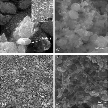
Figure 1 shows raw CNTs, raw silicon carbide nanoparticles, and mixture powders of Zn, CNTs, and silicon carbide nanoparticles after ball milling. During the ball-milling process, intense friction between stainless balls and the mixture powders shaped the Zn powders into Zn flakes [as shown in Fig. 1(c)] and dispersed CNTs and silicon carbide nanoparticles on their surface. It can be seen from Fig. 1(b) that silicon carbide nanoparticles penetrated into CNT clusters. In this way, CNTs were isolated from each other, thereby, prevented the formation of CNT clusters.
Morphologies of (a) raw CNTs accompanied by magnified image as the inset, (b) raw carbide silicon nanoparticles, and (c and d) ball-milled mixture powders.

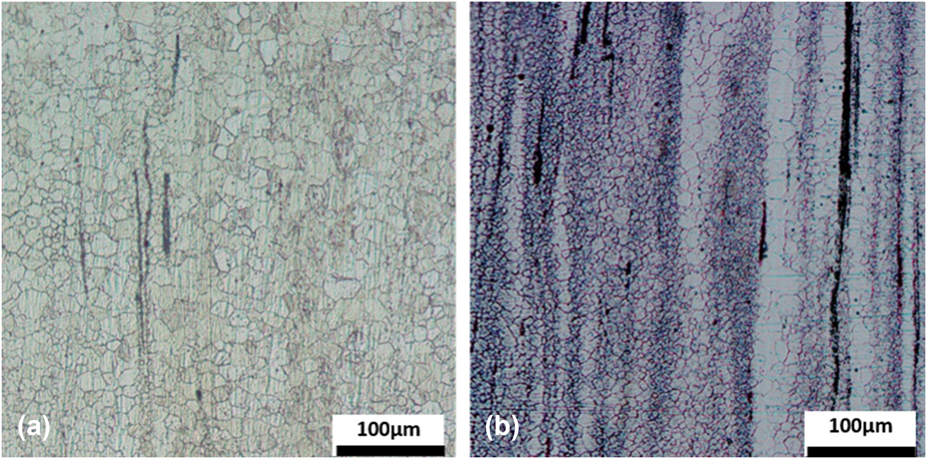
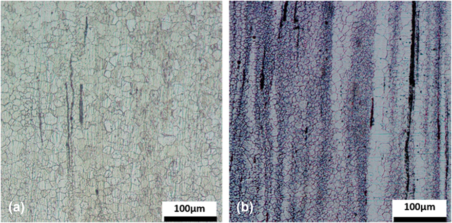
As can be seen from the optical images of the as-extruded alloy and hybrid composite (Fig. 2), a banded structure formed in the composites after hot-extrusion. The grain size varies a lot between the grains in the band (4–7 μm) and those away from the band (20–30 μm), which may attribute to the distribution of the reinforcements. The average grain size of the as-prepared hybrid composites (about 10 μm) and the matrix alloy (about 24 μm) was measured by the linear intercept method. According the Hall–Petch equation, refined grains will increase the strength of the matrix.
Optical images of the (a) as-extrusion alloy and (b) hybrid composite.
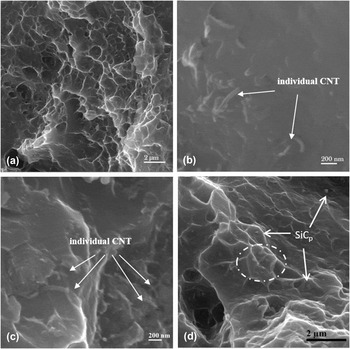
From the observations of the fracture surface of the as-extruded hybrid composites (Fig. 3), the fracture surface is the typical ductile surface with a great amount of dimples on it. Furthermore, an individual pulled-out CNT was found on the fracture surface, which proved the load transfer reinforcing mechanism of the CNTs.
SEM observations of (a) ductile fracture surface of the hybrid composite. (b and c) pulling-out of CNTs on the fracture surface and (d) nano-SiCp at the bottom of the dimples.

Apart from CNTs, good dispersion of silicon carbide nanoparticles made a great contribution to the enhanced mechanical properties as well. As can be seen from the high magnification fractograph of the hybrid composite, randomly distributed silicon carbide nanoparticles can be found at the bottom of the dimples. When loading, these uniformly distributed nanoparticles will impede the immigration of the dislocations, which contributes to the Orowan strengthening mechanism.
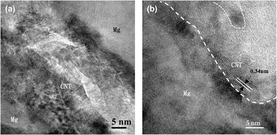
CNTs with hollow structure in the composites were detected by HRTEM observations as shown in Fig. 4. It is clear that the multiwalled structure of CNTs remained after ball milling, mechanical stirring, ultrasonic vibration, and hot extrusion process. Effective interface bonding with no obvious pores between the Mg matrix and CNT was formed as shown in Fig. 4(b). As we all know that fine interface bonding plays a key role in the load transfer strengthening mechanism. Thus, the potential of CNTs can be fulfilled when loading.
(a and b) HRTEM observations of CNTs embedded in the composites.

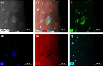
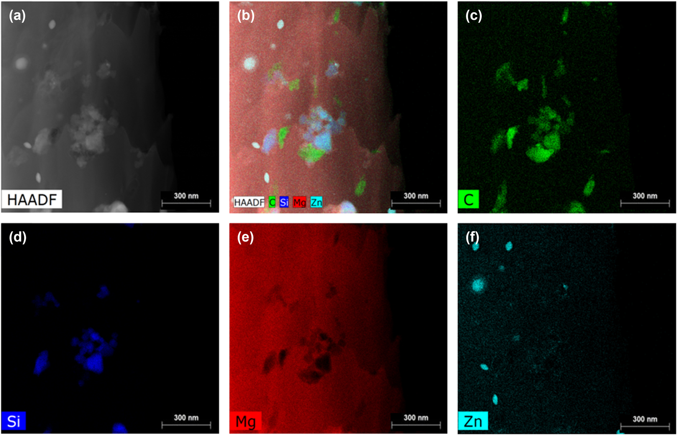
In the hybrid composites, CNTs and silicon carbide nanoparticles reached a uniform distribution together. As shown in Fig. 5, we can see that two kinds of nanoreinforcements interpenetrate with each other, while intercross setting means cooperation when under applied load, which result in the synergetic strengthening effect. Thus, the fabrication process including ball milling, mechanical stirring, ultrasonic vibration, and hot extrusion used in our work is effective in dispersing hybrid nanoreinforcements.
Element surface scan images of the hybrid composites. (a) HAADF image of reinforcements in the composites, (b) surface scan image of all elements in the composites, (c) surface scan image of element C in the composites, (d) surface scan image of element Si in the composites, (e) surface scan image of element Mg in the composites, and (f) surface scan image of element Zn in the composites.
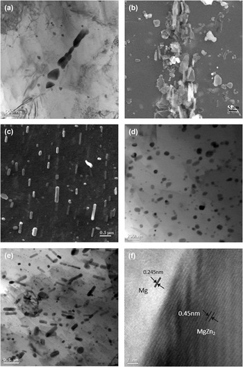
In the Mg–6Zn alloy and Mg–6Zn/CNT composites, there are many precipitations. However, these second phases obtain irregular shape with size up to several micrometers [as shown in Fig. 6(a)]. Especially, in the Mg–6Zn/CNT composites, some CNTs were coated by these big second phases [as shown in Fig. 6(b)]. As recognized, these big brittle precipitations can degrade the mechanical performance and lead to premature failure of the material. Generally, solid solution processes are used to diminish these second phases so as to improve the mechanical properties of the material.
Microstructure of precipitates in the alloy and composites. (a) TEM image of precipitates in the alloy, (b) SEM observation of big second phases in Mg–6Zn/CNT composites, (c) SEM image of the rod-like second phase in the hybrid composites, (d) TEM image of nanosized precipitates in the hybrid composites, (e) TEM image of rod-like precipitates in the hybrid composites, and (f) HRTEM image of the Mg–MgZn2 interface.

Interestingly, a great amount of rod-like nanosized second phases were found in the as-extruded Mg–6Zn/(CNT + SiCp) hybrid composites. Obviously, the precipitation of these fine rod-like phases attribute to the addition of silicon carbide nanoparticles. The morphology of the second phase just like the CNTs expect for shorter length. In addition, the rod-like phase precipitated in a parallel way which aligned along the extrusion direction in the as-extruded composites [as can be seen in Fig. 6(c)]. As recognized, these fine dispersed second phases will retard the grain growth during the hot extrusion and hinder the dislocation motion when loading so as to strengthen the matrix.
In the hybrid composite, silicon carbide nanoparticles dispersed uniformly in the composite which produced a great amount of SiCp/Mg interfaces. These interface areas are lattice distortion zones where the second phases can precipitate easily. Thus, there exist two kinds of second phases in the hybrid composites: (i) big second phases with irregular shape which tend to distribute together with the CNTs; (ii) fine dispersed nanosized rod-like second phases. To sum up, the addition of the silicon carbide nanoparticles changed the size and shape of the second phases as well as their distribution in the composites.
To further investigate the morphology and orientation of the rod-like precipitates in the composite, TEM images and HRTEM images were used. The TEM image presented in Fig. 6(d) shows a great amount of nanosized precipitates in the composites, in which fine dispersed second phase embedded in the Mg matrix with size of just a few tens of nanometers. During the extrusion process, these nanosized precipitates grew into rod-shaped second phase as shown in Fig. 6(e). It is a consensus that these nanosized second phases are desired in the composites because they can refine the crystalline structure of the composite and result in enhanced mechanical behavior.
The HRTEM image as presented in Fig. 6(f) shows the microstructure of the interface between the Mg matrix and the rod-like precipitate in the hybrid composites. It can be seen that no strain fields indicative of misfit dislocations were observed at the Mg/precipitate interfaces, indicating a coherent interface structure. To be more accurate and reliable, the HRTEM image [Fig. 6(f)] was fast Fourier transformed (FFT) to identify the structure and orientation of the particle from the lattice image.
EDS (energy dispersive spectroscopy) analyses in the conventional TEM indicated that the precipitates contain Zn and Mg and the analysis of the FFT image verified that the rod-shaped precipitates were  $\beta _1^\prime$ (MgZn2) phase, which is consistent with related research studies in Mg–Zn alloys.Reference Li, Ma, Dai, Qian, Hu and Xie31
B. Room temperature tensile properties
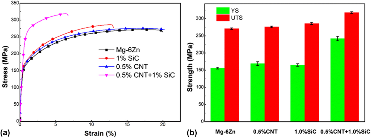
Figure 7 shows room tensile properties of the as-extruded Mg–6Zn alloy and composites with different kinds of reinforcements. As can be seen from the tensile curves [Fig. 7(a)], compared with the matrix alloy, both the yield strength and ultimate tensile strength of the Mg–6Zn/0.5% CNT and Mg–6Zn/1.0% SiC composites increased slightly. Notably, the addition of nano-SiC particles showed better strengthening in comparison with CNT incorporation. The reason may be that during the ultrasonic vibration process, ultrasonic cavitation effect can help to decrease the clusters of raw CNTs and nano-SiC particles. However, due to the high aspect ratio, it is harder to eliminate CNT clusters because CNTs tend to entangle with each other. Thus, the strengthening of 0.5% CNT was not as high as that of 1% nano-SiC in our study.
Tensile properties of the as-extruded Mg–6Zn alloy and composites. (a) Stress–strain curves; (b) YS and UTS with different reinforcements.
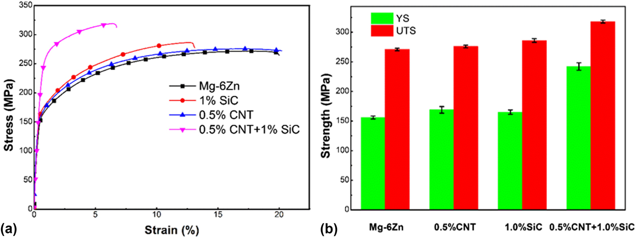
Interestingly, when the CNTs and SiC nanoparticles were incorporated into the matrix simultaneously, the yield strength and ultimate tensile strength of the hybrid composites showed 55.1% and 17.3% increase, respectively, [the strengthening efficiency can be seen more clearly from the column chart in Fig. 7(b)]. Although the fracture strain of the composite exhibited a decrease compared with the matrix (20–6.7%), it has better ductility than composites reinforced by microparticles. The increased strength may be attributed to the refined grain and the uniform distribution of the nanoreinforcements.
During the predispersion process (mixed mechanical ball-milling), the addition of small fraction of silicon carbide nanoparticles facilitated the distribution of CNTs and then resulted in the increase of mechanical properties of the composites. Of course, uniformly distributed silicon carbide nanoparticles made a contribution to the high performance of the hybrid composites as well.
IV. DISCUSSION
In the present work, the grain size of the matrix was significantly refined due to the uniform distribution of nanoreinforcements (CNTs and SiC nanoparticles), which led to the increase of the yield strength. This increment can be calculated by the Hall–Petch relationshipReference Zhao, Zhu, Liu and Bi32:
 $$\Delta {\sigma _{{\rm{GR}}}} = K\left( {{d^{ - 0.5}} - {d_0}^{ - 0.5}} \right)\quad ,$$
where K is a constant, d and d 0 are the average grain sizes of composites and the matrix alloy, respectively.
For the composites reinforced by short fiber or whisker, the load transfer strengthening mechanism was strongly related to the length of the fiber. When loading, a shear stress generated along the matrix–fiber interface transferred from the matrix to fiber. Normally, the shear stress on the fiber increases proportionally from two ends and will peak at the middle of the fiber. Having selected the matrix and the fiber, the strength of the matrix, the fiber, and the matrix–reinforcement interface are constant. The fiber, with different lengths, will induce different modes of pulling-out (pulling-out or pulling-off). Thus, there exists a critical length for CNTs.
In this study, the critical length (l c) can be defined as followsReference Jiang, Li, Fan, Cao and Zhang33,Reference Liu, Xiao, Wang and Ma34 :
 $${l_{\rm{c}}} = {\sigma _{\rm{f}}} \cdot {{{d_{\rm{f}}}} / {{\sigma _{\rm{m}}}}}\quad ,$$
where σm is the strength of the matrix, σf is the strength of the fiber, and d f is the average diameter of the fibers. The calculated l c for the Mg/CNT composites in this study is about 9.8 μm, which is much longer than the CNTs used in this study (below 2 μm). In other words, the shear stress generated on the CNT is lower than its fracture strength and the CNTs will be pulled out directly from the matrix alloy, as shown in Figs. 3(b) and 3(c).
As for composites reinforced by short fiber and whisker when the length of the strengthening materials are smaller than the critical length [as shown in Eq. (1)], the modified shear lag model developed by Nardone and PrewoReference Nardone and Prewo35 might be the most suitable one to predict the strength. Notably, uniform distribution of the reinforcements is the necessary prerequisite for adopting this equation. According to the modified shear lag model, the strength of the composites may be calculated by using the following equtionReference Nardone and Prewo35:
 $${\sigma _{\rm{c}}} = {\sigma _{\rm{m}}}\left[ {{{{V_{\rm{f}}}\left( {s + 4} \right)} / {4 + \left( {1 - {V_{\rm{f}}}} \right)}}} \right]\quad ,$$
where σc and σm are the yield strengths of the composite and matrix, respectively; s is the aspect ratio of the CNTs and V f is the volume fraction of the CNTs.
For the fine particle/metal composites, Orowan strengthening is the main strengthening mechanism. In this work, uniform distribution of CNTs and silicon carbide nanoparticles was achieved; however, only silicon carbide made contribution to the Orowan strengthening since the CNTs mainly distributed along the grain boundaries, as reported in our previous work.Reference Shi, Wang, Li, Hu, Ding, Wu and Huang36 Therefore, silicon carbide nanoparticles led to both grain refinement and dislocation pinning in this study.
The Orowan strengthening effect is given by
 $$\Delta {\sigma _{{\rm{Orowan}}}} = {{0.8 \times {G_{\rm{m}}} \times bM} \over {{L_{\rm{p}}}}}\quad ,$$
where G m is the shear modulus of the matrix; b is the value of the Burgers vector of the matrix; M is the Taylor factor (M is chosen to be 3); L p is the interparticle distance.Reference Li, Viereckl, Rottmair and Singer37
In this study, CNTs made contribution to grain refinement and load transfer strengthening while silicon carbide nanoparticles led to grain refinement and Orowan strengthening. The theoretical yield strength of the as-extruded hybrid composites contributed directly by the hybrid reinforcements can be estimated by the following equation:
 $${\sigma _{\rm{c}}} = \left[ {{\sigma _{\rm{m}}} + K\left( {{d^{ - 1/2}} - {d_0}^{ - 1/2}} \right)} \right]\left[ {{{{V_{{\rm{CNT}}}}\left( {S + 4} \right)} \over 4} + \left( {1 - {V_{{\rm{CNT}}}}} \right)} \right] + {{0.8 \times {G_{\rm{m}}} \times bM} \over {{L_{\rm{p}}}}}\quad .$$
The theoretical yield strength of the composite calculated by Eq. (5) was 225.8 MPa, which is lower than the experimental yield strength (242 MPa). This is unusual for MMCs since the calculation of the theoretical yield strength was premised on uniform distribution of the reinforcing materials. In the actual material, however, the strengthening materials cannot reach uniform distribution and there also exist some microdefects like pores and clusters of reinforcements in the composites. Thus, precipitation strengthening from fine dispersed MgZn2 phases in the composites made a great contribution to the enhanced mechanical properties. Therefore, the theoretical yield strength of the as-extruded hybrid composites can be estimated by the following equation:
 $${\sigma _{\rm{c}}} = \left[ {{\sigma _{\rm{m}}} + K\left( {{d^{ - 1/2}} - {d_0}^{ - 1/2}} \right)} \right]\left[ {{{{V_{{\rm{CNT}}}}\left( {S + 4} \right)} \over 4} + \left( {1 - {V_{{\rm{CNT}}}}} \right)} \right] + {{0.8 \times {G_{\rm{m}}} \times bM} \over {{L_{\rm{p}}}}} + \Delta {\sigma _{\rm{p}}}\quad ,$$
where Δσp stands for yield strength increment caused by precipitation strengthening.
V. CONCLUSION
In this study, Mg–6Zn/(CNT + SiCp) hybrid composites were fabricated by a novel melt spinning process. The microstructure and mechanical properties of the hybrid composites were investigated and compared with the matrix alloy prepared by the same fabrication process. The main conclusions are shown as follows:
(1) During the mixed ball-milling process, the silicon carbide nanoparticles acted as the mixing agent to promote the effect of predispersion. Furthermore, silicon carbide nanoparticles and CNTs isolated each other in the process.
(2) Both CNTs and nanosized silicon carbide particles distributed uniformly in the hybrid Mg–6Zn/(CNT + SiCp) composites, which led to an increased strengthening efficiency of the nanoreinforcements. Uniform distribution of the hybrid nanoreinforcements caused grain refinement, load transfer, and Orowan strengthening mechanism for the hybrid composites.
(3) The addition of the nanosized reinforcements induced the precipitation of a great amount of nanosized rod-like
 $\beta _1^\prime$ (MgZn2) phase in the composites, which made a contribution to the enhanced mechanical performance as well.

ACKNOWLEDGMENTS
This work was supported by “National Natural Science Foundation of China” (Grant Nos. 51471059 and 51671066), “National Key R&D Program of China” (Grant Nos. 2016YFB0301102 and 2017YFB0703100), and Key laboratory of Lightweight and High Strength Structural Materials of Jiangxi Province (No. 20171BCD40003).