INTRODUCTION
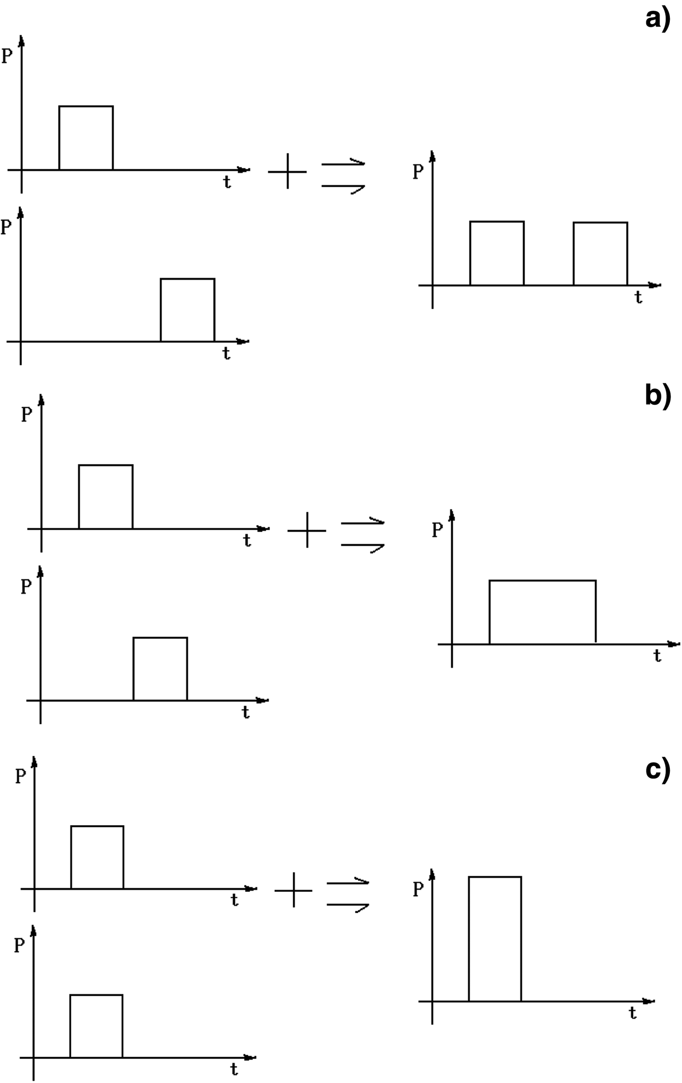
The high power microwave (HPM) is a novel technology developed in recent years (Balanis, Reference Balanis1997; Barker & Schamiloglu, Reference Barker and Schamiloglu2001). It already makes great progress due to bran-new interactional mechanism (Shao & Lui, Reference Shao and Liu2001; Thumm & Kasperak, Reference Thumm and Kasperak2002; Eltchaninov et al., Reference Eltchaninov, Korovin, Rostov, Pegel, Mesyats, Rukin, Shpak, Yalandin and Ginzbure2003; Korovin et al., Reference Korovin, Kurkan, Loginov, Pegel, Polevin, Volkov and Zherlitsyn2003; Andreev et al., Reference Andreev, Gubanov, Efremov, Koshelev, Korovin, Kovalchuk, Kremnev, Plisko, Stepchenko and Sukhushin2003; Luo et al., Reference Luo, Liao, Meng and Zhang2006; Li et al., Reference Li, Chang, Ju, Xiang, Zhao, Gan, Liu, Su and Huang2007; Reference Li, Yuan, Zhang, Shu and Zhang2008; Huang et al., Reference Huang, Gan, Lei, Jin, Ju, Xiang, Feng and Liu2008; Xiao et al., Reference Xiao, Liu and Chen2008; Aria et al., Reference Aria, Malik and Singh2009) and the development of pulse power technology (Liu et al., Reference Liu, Zhan, Liu, Feng, Shu, Zhang and Wang2007; Reference Liu, Li, Zhang and Wang2006; Hayashi et al., Reference Hayashi, Song, Ivers, Flechtner, Nation and Schacter2001; Michael et al., 2000). The applications range of HPM includes both civil and military fields, so different HPM source have been fabricated in the last decades, some of them have reached the power for gigawatt level. Multi-frequency operation, higher pulse repeat frequency (PRF), and higher power are the main purpose for researchers, but it is very difficult to achieve these purposes by single HPM source, the concept of high power microwave synthesis therefore is proposed in recent years. The HPM synthesis includes PRF synthesis, pulse width synthesis and pulse power synthesis and so on. The HPM sources used to synthesize can operate at same or different frequencies and the concepts of different synthesis could be detailed introduced in following. (1) PRF synthesis, from Figure 1a, the synthesis pulse power is unchanged, but the PRF of output pulse is the sum of the PRF for two input pulses. The two input pulses may have the same or different operating frequency and the interval of the pulse can be controlled or not controlled. (2) Pulse width synthesis. In fact, it is a particular form of PRF synthesis, the output time for two series of pulses can be controlled exactly and the interval is equal to the pulse width of the first series of pulse. Form Figure 1b, one series of pulse will be generated when two uncorrelated series of pulses are synthesized and the pulse power is unchanged, but the pulse width is the sum of pulse width of the two pulses. (3) Pulse power synthesis. It also can be thought as a particular form of PRF synthesis. The output time of the two pulses can be exactly controlled and the interval is nearly zero, as shown in Figure 1c, the power of the new pulse is the sum of the two input pulses. For PRF synthesis, the purpose is to achieve combination pulses effect or multi-frequencies effect, so the two input pulses have a minimum correlation. For pulse width synthesis, the time sequence for the pulses must be controlled exactly, so more pulse width effect can be achieved. For pulse power synthesis, the two input pulses must have the same operating frequency and the phase must be controlled exactly, the main purpose is to get higher power and the power effect. For general microwave source which output power is lower than MW, there are manifold methods for synthesizing, but for HPM source for gigawatt class power, other synthesizing methods still have not been reported currently.
Diagram of microwave synthesizing.

Generally, there are two kinds of methods for HPM synthesis, which are wave-guide channel synthesis and free space synthesis. For free space synthesis, the microwave sources used for synthesis are unlimited, but every microwave source must own a transmission and radiation system. The synthesizing result is related with each radiation antenna for a fixed position. For the wave-guide channel synthesis, the microwave sources can share a same transmission and radiation system and the synthesizing result is only related with the radiation system.
A synthesis method for gigawatt class HPM is presented in this paper. According to the coupled wave and orthogonal polarization theory, the gigawatt class HPM could be synthesized from two separate input wave-guides. The design principle and structure of the synthesizer are introduced, and the numerical simulation is used for improving the synthesizer.
The power capability of the synthesizer is emphasized and numerical simulation indicates that the transmission efficiency of the main channel is up to 99%, the coupling efficiency of the sub-channel is greater than 96%, which also validates the feasibility of design for the synthesizer. At the same time, the prototype of synthesizer is fabricated and the HPM equipment system is established, the transmission efficiency of the main channel and the coupling efficiency of the sub-channel are all greater than 95% in cold test condition, they are also above 90% in the test condition of gigawatt class and the power capability of the synthesizer is about 1.2 GW.
THE PRINCIPLE OF THE ORTHOGONAL POLARIZATION COUPLED SYNTHESIZER
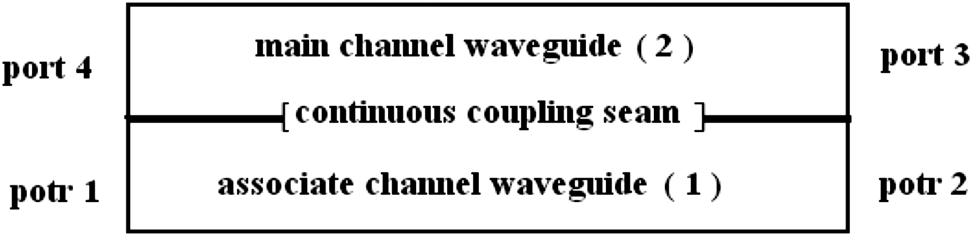
Two circular wave-guides with the same radius are connected back to back, a continuous long-slit is notched at the connection section as the coupled channel. From Figure 2, wave-guide 1 is the sub-channel. There is an initial single pumping signal a 1(0) for port 1. Wave-guide 2 is the main channel. The initial signal is zero for port 4. According to the coupled wave theory, the two wave-guides have the same radius, so the phase-shift coefficient is equal for the single model microwave signals with the same transmission direction, i.e., the synchronization condition (β01 = β02 = β) is satisfied. If the coupling coefficients of the two wave-guides are k 12 and k 21, respectively, for the single model microwave signal, if we want to get the coupled wave in the same transmission direction, it needs to meet the conditions: k 12 + k*21 = 0, |k 12| = |k 21|. As a result, variation of the wave-guide signal with the transmission distance z is presented by Eqs. (1) and (2) (Zhang & Li, Reference Zhang and Li2001) and the intense research could be discussed for the propagation of electromagnetic wave in a rectangular wave-guide from the related references (Malik et al., Reference Malik, Kumar and Singh2008; Aria et al., Reference Aria, Malik and Singh2009; Malik, Reference Malik2003; Malik, Reference Malik2008; Anil et al., Reference Anil and Hitendra2009; Malik & Anil, Reference Malik and Anil2010.
 $$a_1 \left(z \right)= a_1 \left(0 \right)\cos {\rm \beta}_e ze^{ - j{\rm \beta} z}\comma \;$$
 $$a_2 \left(z \right)= a_1 \left(0 \right)\sin {\rm \beta} _e ze^{ - j{\rm \beta} z}.$$
Where, 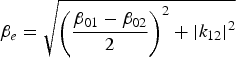 ${\rm \beta}_e = \sqrt{\left(\displaystyle{{\rm \beta}_{01} - {\rm \beta}_{02} \over 2} \right)^2 + \left\vert k_{12} \right\vert^2}$ and z is the location of transmission direction of the signal. The power of the two wave-guides is shown by Eqs. (3) and (4).
 $$\left\vert {a_1 \left(z \right)} \right\vert^2 = \left[a_1 \left(0 \right)\right]^2 \cos^2 {\rm \beta}_e z = \displaystyle{\left[a_1 \left(0 \right)\right]^2 \over 2} \left(1 + \cos 2{\rm \beta}_e z \right)\comma \;$$
 $$\left\vert a_2 \left(z \right)\right\vert^2 = \left[a_1 \left(0 \right)\right]^2 \sin^2 {\rm \beta}_e z = \displaystyle{\left[a_1 \left(0 \right)\right]^2 \over 2} \left(1 - \cos 2{\rm \beta}_e z \right).$$
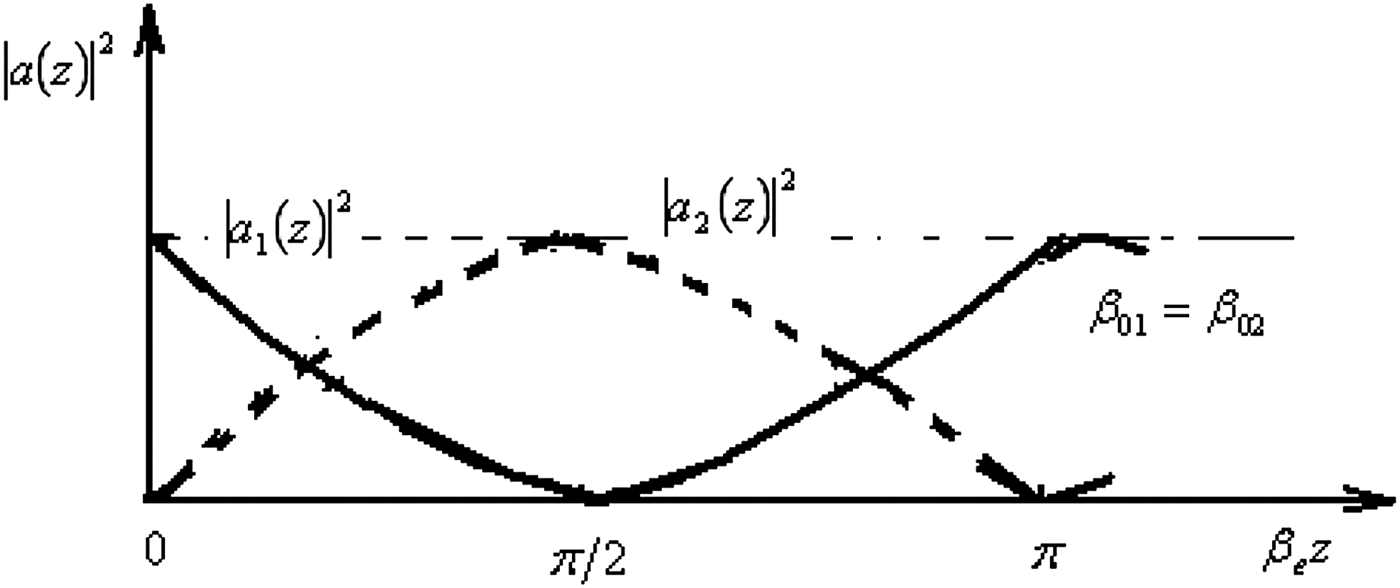
If the length of the long-slit is l and βel = k 12l = π/2, so [a 2(l)]2 = [a 1(0)]2 and a 1(l) = 0, that means no output from the sub-channel and all microwave energy are coupled into the main channel. The relationship between a(z) and the length of the long-slit is shown in Figure 3.
Diagram framework of the synthesizer.
The diagram for the microwave power vs. the length of the long-slit.
For this synthesizer, if the two wave-guides have the same radius, then they will have the same phase-shift coefficient when single mode signal is transmitted in two wave-guides, so it is not difficult to achieve that a single mode microwave signal power coupled into the main channel from the sub-channel. If we import TE011 mode microwave into the sub-channel and import other model microwave into the main channel, or the frequency from two channels is different sharply, it is difficult that the other model microwave is coupled from main channel to sub-channel for coupling structure designed for TE011 mode, it means that two microwave signals with different model can be combined into single signal with higher power. But for HPM application, TE011 mode is the common mode fitting for antenna radiation, so it is necessary to transmit TE011 mode microwave for the two channels of the synthesizer. Generally, according to reciprocal principle, if the two channels have the same model and frequency, then the microwave energy can all couple into main channel from sub-channel and vice versa, which is difficult to achieve higher isolation from main channel to sub-channel. Fortunately, the TE011 mode in circular wave-guide has different polarization direction, so the vertical polarization TE011 mode microwave is infused into sub-channel and the horizontal polarization TE011 mode microwave into main channel, the coupling structure could be designed, which the vertical polarization TE011 mode microwave in sub-channel can all couple into the main channel. Because the input microwave from main channel with horizontal polarization TE011 mode, according to the orthogonal polarization theory, the microwave energy could be coupled into sub-channel and will transmit along with its original way, which leads to the synthesis of two TE011 mode microwaves.
NUMERICAL SIMULATIONS
The following three questions could be answered by using numerical simulations. (1) Whether can the horizontal polarization TE011 mode microwave infused into the main channel transmit to the public output port with high efficiency? (2) Whether can the vertical polarization TE011 mode microwave infused into the sub-channel couple into main channel and export from the public port efficiently? (3) Whether is the power capability of the synthesizer up to gigawatt? The mode of synthesizer for numerical simulation is shown in Figure 4.
(Color online) The coupling model of the synthesizer.
The two wave-guides are connected back to back, which has the same radius (25 mm), the distance between the wave-guides is 1 mm, the width of the long-slit is 6 mm. The microwave frequency is 9.4 GHz, the vertical polarization TE011 mode microwave is infused into port 1 and export from port 3 shown from Figure 5. The variation of coupling efficiency with the long-slit length is shown in Figure 6.
(Color online) The distribution of electric field strength E during the microwave coupling from sub-channel to main channel.
(Color online) The curve of coupling efficiency vs. the length of the long-slit.
The maximum coupling efficiency is 98%, and average value is above 95% when the length of the long-slit varies from 650 mm to 750 mm. If the length of the long-slit is 700 mm, the curve of coupling efficiency vs. microwave frequency is shown in Figure 7. The isolation of port 1 and port 4 of the synthesizer is shown in Figure 8. So, the coupling efficiency can keep greater than 96% for vertical polarization TE011 mode microwave when the microwave bandwidth is about several hundred MHz, at the same time, the isolation is up to −35dB. When the horizontal polarization TE011 mode microwave is infused into port 4 and export from port 3 as shown in Figure 9, the curve of transmission efficiency of the main channel vs. microwave frequency is shown in Figure 10, which can nearly keep greater than 99% in the operating bandwidth, the isolation for port 4 and port 1 is greater than −50dB. The horizontal polarization TE011 mode microwave with frequency 4–12 GHz is infused into main channel and the vertical polarization TE011 mode microwave with frequency 9.2–9.6 GHz is infused into sub-channel. The synthesizer can implement two pulses synthesis, which has efficiency greater than 95% in theory.
(Color online) The coupling efficiency vs. microwave frequency with the long-slit length 700 mm.
(Color online) The isolation of the port 1 and port 4 with the long-slit length 700 mm.
(Color online) he distribution of electric field strength E during microwave transmitting in the main channel.
(Color online) The curve of transmission efficiency vs. the length of the long-slit.
The first and second questions could be solved using numerical simulation method, and the following discusses the power capability of the synthesizer. The key of synthesizer is the high coupling efficiency for sub-channel, the width of the long-slit is generally less than a constant when the microwave frequency and the radius unchanged, narrower long-slit width means longer slit length to achieve higher coupling efficiency, at the same time, the distance between the two wave-guides connected back to back is less than 2 mm for better coupling efficiency, otherwise the coupling efficiency will have an obvious decline. When the wave-guides radius is fixed, lower frequency leads to shorter length and narrower maximum width of long-slit for achieving higher coupling efficiency. For example, if the radius of the wave-guides is 40 mm, the microwave frequency is 4 GHz, and then the maximum long-slit width is about 10 mm, and the relationship of coupling efficiency vs. the long-slit length is shown in Figure 11. The best long-slit length is about 700 mm, the relationship of coupling efficiency versus microwave frequency is shown in Figure 12, and the bandwidth is about 200 MHz. As an example, when the frequency is 2.9 GHz, the maximum long-slit width is about 5 mm, and the coupling efficiency versus the long-slit length is shown in Figure 13.The best long-slit length is about 450 mm, the relationship of coupling efficiency vs. microwave frequency is shown in Figure 14. The bandwidth is about 100 MHz.
(Color online) The curve of coupling efficiency vs. the length of the long-slit (frequency: 4 GHz, long-slit width: 10 mm).
(Color online) The coupling efficiency vs. microwave frequency (long-slit length: 700 mm, long-slit width: 10 mm).
(Color online) The curve of coupling efficiency vs. the length of the long-slit (frequency: 2.9 GHz, long-slit width: 5 mm).
(Color online) The coupling efficiency vs. microwave frequency (long-slit length: 450 mm, long-slit width: 5 mm).
The strength of the coupling microwave's electric field at the long-slit is the key factor to long-slit's width and length when the frequency is fixed. Wider width leads to higher power capability, but wider width also leads to bigger radius and longer length, so the optimization design is necessary. Next, a detailed discussion for the power capability of the synthesizer will be presented.
The high power capability is the significant merit for the synthesizer presented in this paper, which is up to gigawatt class. Generally, the microwave can transmit safely when the electric field is less than 1 MV/cm in vacuum. For example, a synthesizer is composed of two wave-guides connected back to back, the distance between two wave-guides is 1 mm, radius of the wave-guides is 25 mm, long-slit width is 6 mm and length is 700 mm. For a circular wave-guide with radius 25 mm, the maximum electric field is about 320 kV/cm during transmitting TE011 mode microwave with 1 GW pulse power and the field distribution is shown in Figure 15. For the synthesizer, the field distribution is shown in Figure 16 during transmitting TE011 mode microwave with the same pulse power in main channel. The electric-field intensity does not increase obviously, so the conclusion is that the coupling long-slit nearly have no influence for the power capability of the main channel, and the maximum power capability in main channel of the synthesizer is about 10 GW in theory.
(Color online) The distribution of electric field strength E during TE011 mode with pulse power 1 GW in a circle waveguide with radius 50 mm.
(Color online) he distribution of electric field strength E during TE011 mod with pulse power 1 GW in the main channel with the same waveguide radius 50 mm.
For the same synthesizer, the maximum electric-field intensity is about 910 kV/cm when coupling TE011 mode microwave of 1 GW pulse power in sub-channel, and the field distribution is shown in Figure 17. The maximum electric-field intensity is nearly 1 MV/cm, so 1 GW maybe the maximum power capability for the sub-channel of this synthesizer. It is discussed previously that we can increase the wave-guide's radius to increase the power capability; sometimes increasing the long-slit width can also perform the same purpose. All these methods are based on decreasing the electric-field intensity at the long-slit. For example, increasing the wave-guide's radius to 30 mm, long-slit width to 10 mm, and length to 1000 mm, the maximum electric field is about 640 kV/cm during transmitting TE011 mode microwave with 1 GW pulse power, and the field distribution is shown in Figure 18. The coupling efficiency is about 95%, the power capability of the sub-channel is up to 2.4 GW in theory.
(Color online) The distribution of electric field strength E during the microwave coupling from sub-channel to main channel with the pulse power 1 GW and the waveguide radius 50 mm.
(Color online) The distribution of electric field strength E during the microwave coupling from sub-channel to main channel with the pulse power 1 GW and the waveguide radius 60 mm.
EXPERIMENTAL RESEARCHES
For the sake of validating the feasibility of the design, a synthesizer prototype in X band has been developed and the HPM experiment system is established. The picture of synthesizer is shown in Figure 19, which includes input parts, coupling parts, and output parts and so on. The input part is composed of a right circular wave-guide and a 90° bend circular wave-guide, which can be infused with two series of pulses simultaneously. The coupling parts uses two circular wave-guides connected back to back, which couples energy from the sub-channel to the main channel efficiently. The output part is composed of a longer right circular wave-guide and a short right circular wave-guide. The short wave-guide is connected to the sub-channel wave-guide and the absorbing materials or short circuit plane is connected to the terminal of synthesizer due to the isolation index. The longer wave-guide is connected with the main channel wave-guide and the output port is the public output port of the synthesizer. The parameters of the synthesizer include the distance between two straight wave-guides: 1 mm, radius: 40 mm, long-slit width: 12 mm and length: 1600 mm. The HPM experiment system is shown in Figure 20, which includes the HPM source, the mode convertor, the online power measurement devices for the input of the synthesizer, the synthesizer, the online power measurement devices for the output of the synthesizer, and the emission antenna, and all the devices are presented in the picture.
(Color online) The diagram of the synthesizer structure.
(Color online) The X band HPM equipment system for the synthesizer.
The transmission efficiency of the main channel is about 96% and the coupling efficiency of the sub-channel is about 95% when the synthesizer is tested at the gigawatt class. The vulnerable part of the synthesizer is the coupling long-slit due to the limited the power capability. As discussed previously, numerical simulations indicate that the power capability of the main channel is about 10 GW and also achieve gigawatt class in sub-channel. The waveforms are shown in Figure 21 when the transmission power is 1.5 GW in main channel. Figure 22 shows the waveforms when the coupling power is about 1.2 GW in sub-channel.
(Color online) The pulse waveforms when the transmission power is 1.5 GW in main channel.
(Color online) The pulse waveforms with the coupling power about 1.2 GW in sub-channel.
The diode voltage waveforms of the accelerator, the online microwave waveforms after the output of the synthesizer, the online microwave waveforms before the input of the synthesizer, and the microwave waveforms of radiation field are displayed from channels 1, 2, 3, 4 of the oscilloscope, respectively, in Figures 21–24. The breakdown could be detected by collating the I/O waveforms of synthesizer. A little breakdown phenomenon has been detected when the coupling power is greater than 1.2 GW. The waveforms are shown in Figures 23 and 24 when the coupling power is 1.3 GW and 1.4 GW. It indicates that the power capability of the sub-channel of this synthesizer is about 1.2 GW, the pulse width is about 20 ns. Certainly, the power capability of the synthesizer also depends on the vacuum degree, which is about 5 × 10⁻²Pa. If the vacuum degree increases, the power capability may have a great increase.
(Color online) The pulse waveforms with the coupling power about 1.3 GW in sub-channel.
(Color online) The pulse waveforms with the coupling power about 1.4 GW in sub-channel.
CONCLUSIONS
A HPM synthesis method for gigawatt class is presented in this paper based on the coupled wave and the orthogonal polarization theory. Numerical simulations indicate that the design method of the synthesizer is reasonable and exercisable according to experiment results. For the synthesizer, both the transmit efficiency of the main channel and the coupling efficiency of the sub-channel are up to 95%, and the power capability is up to gigawatt class. It is not difficult to achieve pulse width and PRF synthesis for HPM by the presented method, which leads to a good prospect for applications.