1. Introduction
Soft miniature robots [Reference Ng, Tan, Xu, Yang, Lee and Lum1], ranging from nanometres to millimetres, have attracted considerable attention in recent years due to the rapid advances in material fabrication and mechanical manufacture technologies [Reference Stano and Percoco2, Reference El-Atab, Mishra, Al-Modaf, Joharji, Alsharif, Alamoudi, Diaz, Qaiser and Hussain3]. Soft robots have an unmatched advantage to adapt various unstructured environments with respect to their rigid counterparts, demonstrating unprecedented unique applications prospects [Reference Gao, Wei, Chao and Yao4–Reference Kolachalama and Lakshmanan6], such as precise surgery [Reference Taylor, Montayre, Zhao, Kwok and Tse7], targeted examination [Reference Ribuan, Wakimoto, Suzumori and Kanda8], under-water explorations [Reference Wu, Yang, Wu, Zhou, Wang, Zhang, Luo, Chepinskiy and Zhilenkov9] and drug delivery [Reference Yim and Sitti10]. Moreover, soft robots can exhibit safe interaction performances with human body and great flexibility to respond because of their high compliance and adaptability [Reference Lee, Kim, Kim, Hong, Ryu, Kim and Kim11]. Inventing new typed robots posts great challenges to scientists and engineers, as it deals with many multidisciplinary knowledge, including mechanics, materials, physics, chemistry, etc.
The central task for robots is the actuation to achieve specific functions, and various methods have also been explored by inputting external energy. For instance, Sun et al. [Reference Sun, Liu, Ma, Li and Zhou12] reported two versions of prototypes on soft mobile robots actuated by the dielectric elastomer. In service, the robots depend on the foldable behaviour to drive their wheels to move forward, demonstrating a flexible locomotion performance. In succession, Wang et al. [Reference Wang, Han, Wu, Dong and Zhao13] proposed an untethered light-driven robot with integration of motion and location which provides an innovative strategy for the design of crawling robots. Terryn et al. [Reference Terryn, Brancart, Lefeber, Assche and Vanderborght14] generalised the self-healing soft pneumatic actuators to applications, and the products include a soft gripper, a soft hand and artificial muscles. Although these concerned actuators ensure the specific locomotion, extra complex conditions are required during the experimental process and the existing methods are not sufficiently perfect. For example, the pneumatic actuator with airways increase the redundancy of the system, and light- and temperature-driven methods are strongly strict with the local environment.
To overcome the shortcomings of the above methods, magnetic actuators become the focus of recent studies [Reference Bira, Dhagat and Davidson15–Reference Kim and Zhao17]. The magnetic actuation enjoys the preferred concentration owing to its great controllability and manoeuvrability, as well as the relatively safe contact with biological tissues. Furthermore, the magnetic actuation possesses a contact-free form to penetrate into most materials, which would engender harmlessly invasive operations.
As a result, soft magnetic components can be actuated under the corresponding external magnetic field. By different configuration designs and magnetisation methods, soft magnetic robots can exhibit diverse forms of locomotion and deformation. Hu et al. [Reference Hu, Lum, Mastrangeli and Sitti18] proposed a magneto-elastic soft robot at the millimetre scale, which can swim in water, roll and walk on solid surfaces and jump over obstacles when the external magnetic field is applied. Lee et al. [Reference Lee, Jeon, Lee, Jeong and Kim19] developed a magnetically actuated walking soft robot, and it could be moved by varying the magnetic flux density and alternating the on-off state. Moreover, Maeda et al. [Reference Maeda, Shinoda and Tsumori20] fabricated a crawling magnetic robot and investigated its characteristics of movement. The robot could generate a wavy motion under a rotating magnetic field, which is made of silicone and magnetic rubber. Inspired by arthropod species, Sun et al. [Reference Sun, Jia, Yang, Chen, Tan, Deng and Tang21] proposed several magnetic soft millirobots with joint structures by 3D printing hydrogels, and they presented the ex vivo experiment to demonstrate their locomotion ability. In addition, Yim et al. [Reference Yim and Jeon22] invented a magnetic capsule robot which can crawl in a fluid-filled tube, and they provided several critical discussions to inspire future strategies. Kim et al. [Reference Kim, Yuk, Zhao, Chester and Zhao23] reported 3D printing of programmed ferromagnetic domains which enable fast transformations between complex 3D shapes via magnetic actuation and demonstrated diverse functions. Achieving stability of the robot under a given magnetic field [Reference Li, Lau, Yuan, Aggarwal, Dominguez, Liu, Sai, Palmer, Sather, Pearson, Freedman, Amiri, Cruz and Stupp24, Reference Yeow, Yang, Kalairaj, Gao, Cai, Xu, Chen and Ren25] is also important with various bio-inspired configurations [Reference Kim, Laschi and Trimmer26] such as fish [Reference Kim, Shin, Hashi and Ishiyama27–Reference Tomie, Takiguchi, Honda and Yamasaki29], inch-worm [Reference Kalairaj, Cai, Pavitra and Ren30–Reference Zimmermann, Naletova, Zeidis, Turkov, Kolev, Lukashevich and Stepanov32], jellyfish [Reference Ren, Hu, Dong and Sitti33, Reference Ko, Na, Lee, Cha, Ko, Park and Park34], sea anemone [Reference Wang, Wu, Huang, Du, Yue, Chen, Li and Su35] and octopus [Reference Dai, Liang, Chen, Feng, Chen, Song, Bai, Zhang, Feng and Arai36], which can realise multimodal locomotions, including crawling, floating, bending and shrinking.
It is noted that the critical issue of analysing and predicting robots’ deformation under the magnetic field is to probe the mechanism of each sub-component with corresponding magnetisation. For the complex mechanical behaviours of locomotion and deformation under the action of the magnetic field, the robot is accompanied with very strong nonlinearity due to large deformation, as well as the multi-field coupling between the mechanical load and the magnetic field. Herein, we propose a series of soft magnetic robots based on elementary geometries shapes that can achieve multi-functions including moving, crawling, warping and flipping.
The outline of this article is structured as follows. In Section 2, we introduce the experimental materials and fabrication technique for the soft magnetic robots. In Section 4, we demonstrate a complete framework of the numerical simulation, which contains the origins of the magnetic force and torque, and the specific simulation method in COMSOL. Section 5 illustrates the first typical example of the triangular robot, where two locomotion patterns, that is, moving and warping, are introduced in detail by experiments and simulations. In Section 5, we generalise the analysis on triangular-shaped robot to other robots with various geometries, including the cross-shape, square, pentagram and arch-shape. The mechanical responses under the magnetic actuator are comprehensively surveyed. Finally, the conclusions are made based on the above analyses.
2. Material fabrication
The material of the robot is a kind of composites, where the pure silicone gel is viewed as the matrix, and NdFeB powders are selected as the inclusions. Two types of silicone gels, that is, type A and type B, have been purchased from the Shenzhen Talent Young Technology Co., Ltd. The mixing of type A and type B with an equal weight after solidification forms the soft silicone gel, whose specific parameters are given as follows: the Shaw hardness is 10 A, the tensile strength is 2.0
 $\pm$
0.5 MPa, the tear strength is 8
 $\pm$
2 N/mm, the percentage of breaking elongation is 800
 $\pm$
50
 $\%$
, and the shrinkage ratio is <0.1
 $\%$
. These data were provided by the above-mentioned corporation.
In the experiment, the rare earth permanent magnet material NdFeB has high remanence and coercivity, which is suitable for preparing the material for magnetically driven micro-robots. We purchased the magnetic NdFeB powders from the Angstar New Carbon Material Changzhou Co., Ltd.
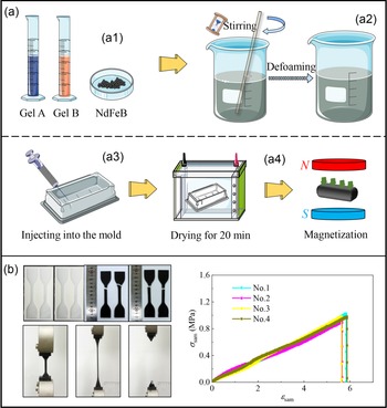
The three main steps of the fabrication process are schematised in Fig. 1(a). First, the two kinds of pure silicone gels, that is, type A (10 g) and type B (10 g) with an equal weight are poured in the beaker, then the NdFeB powders with the half weight (10 g) of the mixed silicone gel are added, as shown in Fig. 1(a1). Next, as demonstrated in Fig. 1(a2), the silicone-NdFeB mixture has been stirred for 10 min, and the vacuum machine (MP-50C, Shanghai Yiheng Scientific Instrument Co., Ltd.) is used to remove the bubbles in the mixture. After that, the prepared silicone-NdFeB mixture is injected into the mold, and then the mold is placed in the drying box with the temperature of 60°C for 20 min. Finally, the dried silicone mixture is peeled from the mold, and then it is fixed under a magnetic field generator (PE-5005H, Sichuan Litian Magnetic Technology Co., Ltd.) for magnetising, as shown in Fig. 1(a4).
Preparation and tensile test of the composite material for the magnetic robot. (a) Preparation of the composite material. (a1) Mixing of type A, type B gels and NdFeB powders. (a2) Stirring of the mixture and the bubbles are removed under the vacuum condition. (a3) The prepared magnetic silicone is injected into a 3D-printing mold for drying, curing then demoulding. (a4) Magnetisation. (b) The tensile test and result curves.

In order to illustrate the mechanical properties of the composite material, tensile tests are carried out with the same weight ratio of the materials. We select silicone A (35 g), silicone B (35 g) and NdFeB powders (35 g), four standard samples are made without magnetisation. Fig. 1(b) shows the dumbbell-shaped molds, four samples after fracture and the stress–strain curves corresponding to the four tests. The curves denote that the stiffness of the composite material in tensile test is approximately 0.2 MPa.
3. Framework of the numerical simulation for the magnetic field
According to the theory of electro-magnetic field, the locomotion and deformation of robots can be realised by remotely applied magnetic field which exerts forces and torques on them. When placed in a non-uniform magnetic field, the magnetic force per unit volume
f
 $_m$
exerted on the magnetic dipole expressed as
 \begin{equation} {\boldsymbol{f}}_{m}=({\boldsymbol{M}}\cdot \nabla ){\boldsymbol{B}} \end{equation}
where M and B represent the magnetisation and magnetic flux density, respectively.
A magnetic torque per unit volume is also produced when the magnetisation of the object misaligns with the magnetic field, which can be written as
 \begin{equation} \boldsymbol{\tau }_{m}={{\boldsymbol{M}}}\times{{\boldsymbol{B}}} \end{equation}
Due to the complexity of the considered problem, that is, it deals with the interaction between the deformation of the robots and the magnetic field, the force analysis is performed via the numerical simulation scheme. We conduct the simulation by using the magneto-mechanics with no currents module in COMSOL Multi-physics, with the version of 6.0.
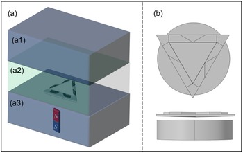
First, we establish a bounding air box (400 mm
 $\times$
400 mm
 $\times$
300 mm) to compute the magnetic field, and the selected air domain is divided into three layers as shown in Fig. 2(a). In addition, a moving mesh area is set up in the middle layer to include the effect of the distance variation when the robot is deformed by the magnetic field as shown in Fig. 2(b). Then, all the objects in simulation are defined as those with magnetic flux conservation. The actuated permanent magnet whose radius and thickness are, respectively, 50 mm and 10 mm, is made of the N35 sintered NdFeB material. The recovery permeability of the magnet is 1.05, and the residual flux density is 1.21 T. The permanent magnet is fixed in space and its deformation is ignored during the simulation process.
Numerical simulation. (a) Schematic diagram of numerical simulation where the whole bounding box is divided into three layers, namely (a1), (a2) and (a3). Layer (a2) only contains the magnetic robot and Layer (a3) only contains the permanent magnet. (b) Schematic diagram in COMSOL (air domain is hidden).

The residual flux density model is chosen as the B-H constitutive model to calculate the deformation of robots, where the magnetisation direction is determined according to the experimental process, and its deformation is the main concern. Then, we set free tetrahedral meshes in the whole air domain, with the maximum element size (side length of the element) of approximately 25 mm. The maximum element sizes of the permanent magnet and the magnetic robot are set to 2 mm and 1 mm, respectively. Finally, we build a parametric sweep solver to obtain the deformation of the robot with different magnetic flux densities.
4. Typical robot with a triangular shape
4.1. Preparation and loading
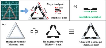
Without loss of generality, we engineer the first typical robot with a triangular shape based on the prepared material in Section 2. The mature soft triangular robot is made of several thin plates as shown in Fig. 3(a), with each side length being 40 mm and each width being 4 mm. The two right-angled trapezoids made of silicone mixture are selected for magnetisation on each side, corresponding to the black parts in Fig. 3(a). The magnetising direction of the right-angled trapezoid is from the right angle to the hypotenuse, which is shown in Fig. 3(b). In order to enhance much wider applicability and flexibility, the white parts in the absence of magnetisation are designed to be hollow, which can reduce the weight and achieve better stability. Furthermore, Fig. 3(c) elaborates the details of the construction, which contains two main components, that is, a hollow triangular baseplate (made by silicone mixture without NdFeB powders) and six magnetised parts (made by magnetised silicone). The six parts can be magnetised, respectively, according to direction requirements and then the two components are glued with silicone mixture and dried for 20 min.
Triangular-shaped robot. (a) Configurations which contains the black (with magnetisation) and white (without magnetisation) parts. (b) Magnetisation direction of the black parts. (c) Construction of the robot.

When loading, a cylindrical NdFeB permanent magnet with the radius being 50 mm and the thickness being 10 mm is selected as the magnetic actuator. The magnetic induction intensity at the centre of the permanent magnet surface is 50 mT. The robot is placed on a thin plate whose thickness is approximately 1 mm, then we move the permanent magnet in different paths under the plate, to induce corresponding locomotion and deformation of the robots.
4.2. Locomotion: moving forward
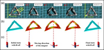
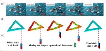
We first consider the motion of the robot under the action of the magnetic field. As shown in Fig. 4(c), we manipulate the magnetic actuator from one of the vertex to its opposite side, and the triangular robot arches up within a short time and the selected vertex moves forward. Then, the height of the arch reaches its maximum value and the other two vertexes “push” the body to keep moving, which accomplishes a complete locomotion cycle. By selecting different vertexes as the starting points, the robot can move along three directions. Figure 4(a) and 4(b) depict the locomotion behaviours and simulation results. Obviously, the simulation results are in excellent agreement with the experimental phenomena.
Moving behaviours of the triangular robot actuated by the magnet. The timeline 00:00:00:00 represents hour, minute, second and frame, respectively, where 24 frames equal 1 s and all the pictures below use the same timing method. (a) Physical modes of the locomotion. (b) Simulated modes of the locomotion. (c) Moving path of the magnetic actuator.

Moreover, the locomotion is resulting from the “arch-push” behaviour under the action of the magnetic field, which can be characterised in detail by the dimensional analysis. The variables involved in deformation include the height of the centroid
 $\textit{H}_{t}$
, the magnetic field density
B
, the magnetisation of the robot
M
, the volume V and the Young’s modulus E of the material. It can be seen that, there are four basic dimensions and five physical quantities, so one dimensionless quantity can be generated. As a consequence one can get
 \begin{equation} \textit{H}_{t}\sim \textit{M}\textit{B}\textit{V}^{ \frac{1}{3}}/\textit{E} \end{equation}
Equation (3) shows that the height of the centroid is proportional to the magnetic flux density B , the magnetisation M and subtriplicate of the volume V, but it is inversely proportional to the elastic modulus E. It indicates that, if the magnetic field is more powerful, the deformation of the robot is more significant. In what follows, this dimensional analysis result would be compared with the numerical simulation.
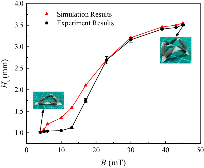
Figure 5 demonstrates the experimental process to determine the relationship between the magnetic density
B
and the height of the centroid
 $\textit{H}_t$
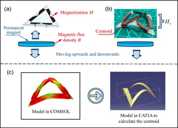
. The magnetic robot is placed on the baseplate, and the centroid’s height is recorded by altering the magnetic flux density. Then, we simulate the experiments in COMSOL and rebuild each deformation results in CATIA to figure out the coordinates of the centroid.
Schematic diagram of the experimental process to measure the centroid. (a) When the magnetic actuator is moving up and down, the height of the centroid is recorded. (b) The centroid’s position during deformation. (c) The deformation obtained in COMSOL and the deformable robot is rebuilt in CATIA in order to calculate the centroid.

In order to reduce the error of artificial measurement during the experiments, we have repeated five times for each set of experiments in this paper and plotted the error bar graphs of each experiment. The numerical simulation and experimental results on the centroid induced by the magnet are shown in Fig. 6. It can be seen that the two curves from different routes are in good agreement. Then, analysis of variance is carried out to illustrate the consistency of experiment and simulation. The results show that the Pearson correlations coefficient is 0.9913 and the P-value is 3.05
 $ \times\, 10^{-9}$
. The standard deviations are 1.0562 and 1.1232 corresponding to simulation group and experimental group, respectively. Also, the dimensional analysis indicates that the height of the centroid is proportional to the magnetic density, and this trend is the same as the numerical and experimental results, although there exist errors. It is noted that in the initial stage, the magnetic field density before 14 mT has little influence on the deformation of the robot, and actually the frictional force dominates the centroid’s height. This feature corresponds to the phenomenon that the curve exhibits a horizontal line at the beginning. After a while, when the magnetic density reaches the value of 17 mT, a linear relationship occurs which is consistent with the result from the dimensional analysis. Especially, the highest point of the centroid is approximately 3.5 mm high under the magnetic density of 45 mT. Both of the simulation result and the experimental result show that the height of the highest point is around 3.7 mm.
The relationship between the magnetic density B and the height of the centroid
 $H_{t}$
.

4.3. Warping
As shown in Fig. 7(a) and (b), the second behaviour of the triangular robot is folding up and warping with the action of the magnetic actuator, where both of the experimental and numerical results are given. Figure 7(c) illustrates the moving path of the magnet, where the magnet is placed perpendicular to one of the vertexes and it is manipulated upwards and downwards.
Warping behaviour of one vertex of the triangular robot under the magnetic actuator. (a) Physical model of the warping process. (b) Simulation result of the deformation. (c) Moving path of the magnetic actuator.

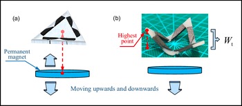
When the magnetic actuator approaches the robot vertically, it can be found that the front part responds very quickly with a slight warping. When the magnet moves up, even half of the robot is lifted off the baseplate. We then place the magnet beneath the robot as shown in Fig. 8(a). It can be imagined that the completely symmetrical structure ensures a symmetrical deformation, where simultaneously the three vertices are warping up with the same angle, which is shown in Fig. 8(b).
Schematic diagram of the warping process. (a) When the magnetic actuator is moving up and down, the height of the vertex is recorded. (b) Physical model of the experimental process.

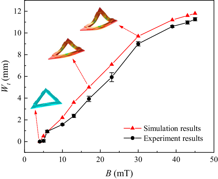
The relationship between the height of vertex to the baseplate
 $\textit{W}_t$
and the magnetic field density
B
is plotted as a curve in Fig. 9. When the magnet moves towards the robot, three vertexes warp within a short time, maintaining an equilibrium state through the three midpoints on each side. During the movement of the magnet, the maximum value of
 $\textit{W}_t$
is approximately 11 mm in the experiment, and 12 mm in simulation with the magnetic density of 45 mT, that is they are very close. Furthermore, the deformation curve of the warping behaviour in the experiment is consistent with the numerical results. Also, analysis of variance is carried out to demonstrate the consistency whose standard deviations are 4.6891 and 4.5677 corresponding to simulation group and experimental group, respectively. Pearson correlations coefficient is 0.9963, and the P-value is 6.63
 $\times \,10^{-11}$
.
Simulation and experimental curves regarding the relationship between the magnetic flux density B and the warp height
 ${W}_t$
.

5. Generalised examples for the robots
5.1. Cross-shaped robot
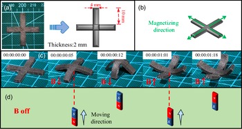
In what follows, we generalise the versatility of the geometric shapes to fabricate some other typical robots. As shown in Fig. 10(a), four identical strips with each length being 10 mm and width being 4 mm can be assembled into a cross-shaped robot. The magnetising direction of each strip is from the centre to outside, as shown in Fig. 10(b). Figure 10(c) shows the two kinds of motions in an alternating magnetic field. It is displayed that, the first deformation becomes an arched configuration when the magnetic field is applied vertically downward, and the second deformation is accompanied with the grabbing behaviour when we reverse the magnetic field.
The cross-shaped robot. (a) Configuration and dimension. (b) Magnetising direction of each part of the robot. (c) The magnetic field drives the robot to realise the arched configuration and grabbing behaviour. (d) Moving direction of the magnet.

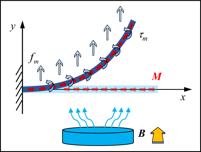
Let us further probe the deformation mechanism of the element of the robot. We select a quarter of the crossed structure and abstract it to a cantilever model owing to the symmetric property, as shown in Fig. 11.
The simplified cantilever model in the magnetic field.

It can be assumed that the direction of the magnetic field is vertically upwards and the magnetisation direction of the cantilever is horizontal from the left to right. As mentioned above, there must be a distributed force
 ${\boldsymbol{f}}_{m}$
and a distributed couple
 $\boldsymbol{\tau }_{m}$
applied on the cantilever. The length of the cantilever is L and the thickness is t. The maximum deflection of the beam is denoted by
 $\delta$
, which is correlated with the Young’s modulus of the beam E, the thickness t and length L, the magnetisation
M
and the magnetic flux density
B
. Based on the principle of dimensional analysis, the maximum deflection of the beam can be expressed as
 \begin{equation}{\delta }\sim \textit{M}\textit{B}\textit{L}^{3}/\textit{E}t^{2} \end{equation}
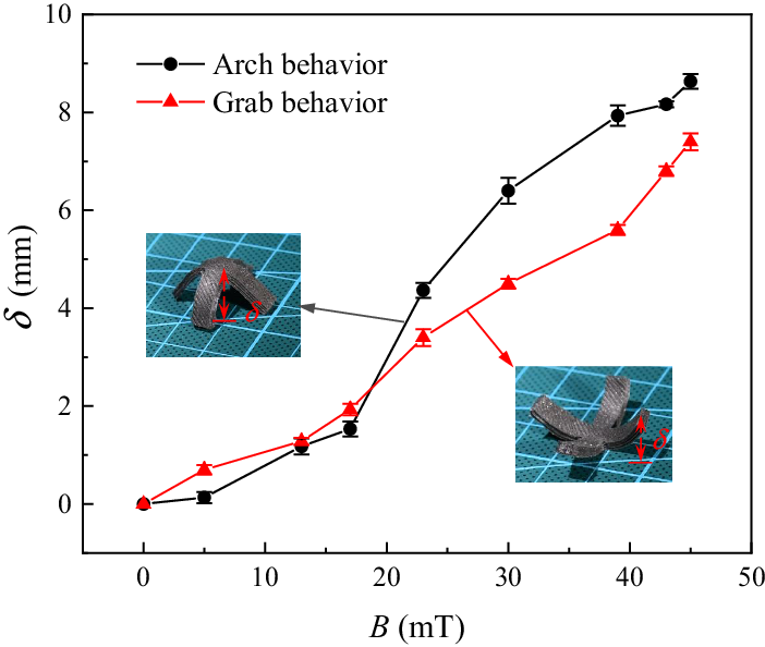
From Eq. (4) it can be seen that the magnetic flux density
B
of the permanent magnet is proportional to the maximum deflection, which roughly agrees with the experimental curves in Fig. 12. Equation (4) also indicates that a larger aspect ratio
 $L^{3}$
/
 $t^{2}$
can promote the deformation, and this agrees with our normal knowledge.
The relationship between the magnetic field density and the maximum deflection of the beam regarding the arched configuration and grabbing behaviour.

5.2. Pentagram-shaped robot
Next we consider the pentagram-shaped robot, which consists of five strips and the angle between each two strips is 72
 $^{\circ }$
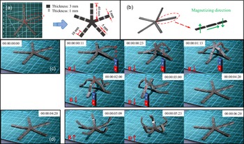
. The normal length of each strip is 40 mm and the width is 5 mm. We divide each strip into three larger subsections whose thickness is 3 mm, corresponding to the black parts and two smaller subsections whose thickness is 1 mm, corresponding to the grey parts in Fig. 13(a). Then we select the three larger parts of each strip to set the magnetisation direction. The magnetisation direction of the innermost part to the centre is vertically upwards, and that of the outermost part is vertically downwards, while that of the middle part points horizontally to the outside, which is illustrated in Fig. 13(b). Combined with such a magnetisation strategy, two main behaviours including crawling and grasping are shown in Fig. 13(c) and (d), respectively.
Pentagram-shaped robot. (a) Configuration and dimension. (b) Magnetising direction of each part of the robot. (c) Crawling of the robot driven by the magnetic field. (d) Gripping motion driven by the magnetic field.

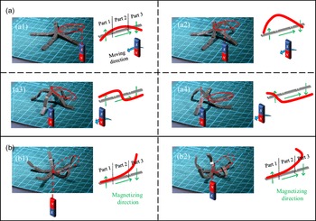
We first analyse the crawling behaviour of the robot. One strip, that is, the red circled part is selected in Fig. 13(b) for analysis, whose magnetising direction is given in Fig. 13(b). As shown in Fig. 14(a1), when we move the permanent magnet under part 3 of the element, part 3 remains still owing to its magnetisation direction is consistent with the magnetic flux density, while part 2 is lifted up by the magnetic torque and then part 3 is caused to the arch. Then we keep moving the permanent magnet, the strip reaches the maximum height of the crawling process, and it is found that the position of the highest point corresponds to the intersection of part 1 and part 2. When we move the magnetic actuator below the centre of the robot, it demonstrates a centrosymmetric form as shown in Fig. 14(a3). Part 1 is parallel to part 3, and part 2 is approximately perpendicular to part 1 and 3. Finally, when we move the magnet to the other side of the robot, we find that Fig. 14(a2) and 14(a4) are symmetrical.
Crawling and grabbing behaviours of the robot under the action of magnet. (a) Crawling behaviour with the movement of the actuator, and different forms are shown in a1 to a4. (b) Grabbing behaviour with the movement of the actuator, and different forms are shown in b1 to b2.

Another deformation for the robot is grabbing objects as a gripper. When we apply an upward magnetic field as shown in Fig. 14(b), five strips of the robot are symmetrically distributed in total, and the magnetising method can make sure that the straight strip bends into the gripper-like shape. The experiment shows that the gripper can reach its maximum deformation when the magnetic density is 35 mT.
Based on the locomotion patterns, the pentagram-shaped prototype demonstrates flexible abilities for cargo delivering in narrow and flat area with crawling motion. While reversing the magnetic field, grabbing and lifting objects can be achieved.
5.3. Pentahedron-shaped robot
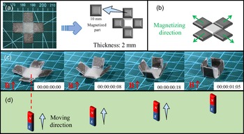
We place four magnetised squares around an unmagnetised square and each side of the square is 10 mm, as shown in Fig. 15(a). The magnetisation direction for each square is from the centre to the outside, which is schematised in Fig. 15(b). Then, a transformation from the 2D flat to the 3D structure can be realised when we apply a vertically upward magnetic field, which is shown in Fig. 15(c).
Pentahedron-shaped robot. (a) Configuration and dimension. (b) Magnetisation direction of each part of the robot. (c) The magnetic field drives the robot to realise wrapping. (d) Moving direction of the magnet.

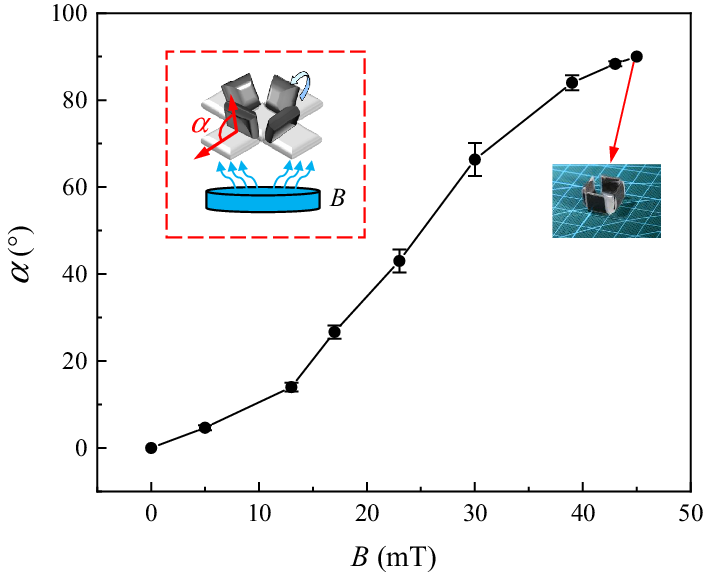
The angle between the inclined square and the horizontal plane is denoted by
 $\alpha$
, which is shown in Fig. 16. Then we move the magnetic actuator to alter the magnetic field density
B
, and then the relationships between
 $\alpha$
and
B
are demonstrated in Fig. 16. It is found that the angle during deformation is approximately proportional to the magnetic field density. Especially, when the magnetic density is 45 mT, the value of
 $\alpha$
becomes 90
 $^{\circ }$
, and the whole configuration can form a box, which is suitable for grabbing targeted objects with small volume.
The relationship between the magnetic field and the deformation angle.

5.4. Hexahedron-shaped robot
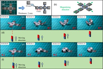
A more complicated robot is the hexahedron-shaped one, where six magnetised squares are connected by five unmagnetised parts, corresponding to the white rectangular parts in Fig. 17(a). The side length of each square is 10 mm, the width of the connection part is 4 mm and the thickness of the robot is 2 mm. Figure 17(b) illustrates the magnetisation direction of each part. When we apply the upward magnetic field, the 2D flat robot transforms to the 3D cubic structure, exhibiting a closure deformation as shown in Fig. 17(c). Then we reverse the magnetic field, the robot arches up in the opposite direction, and it looks like a turtle.
Hexahedron-shaped robot. (a) Configuration and dimension. (b) Magnetising direction of each part of the robot. (c) The closure motion under an upward magnetic field. (d) Moving direction of the magnet in closure motion. (e) The arch motion under a downward magnetic field. (f) Moving direction of the magnet in arch motion.

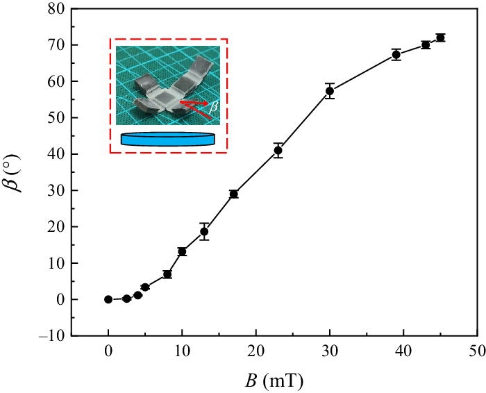
We move the magnetic actuator towards the robot, then measure the angle
 $\beta$
(marked in the subfigure in Fig. 18) at the end of each movement, as schematised in Fig. 18. It is found that the maximum angle that the robot can reach is approximately 70
 $^{\circ }$
when the magnetic flux density is 45 mT. The closure and arching motions propose a strategy for picking and wrapping small cargoes.
The experiment results on the relationship between the magnetic field density and the measured angle. The subfigure is the schematic of the experimental setup, where the characteristic angle is defined.

5.5. Arch-shaped robot
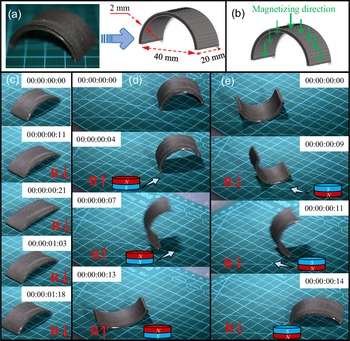
The last robot is the arch-shaped one, whose thickness is 2 mm, and the width and span are 20 and 40 mm, respectively, which are characterised in Fig. 19(a). Then we set the magnetisation direction perpendicular to the surface, corresponding to Fig. 19(b). Three locomotion modes can be realised through the exerted magnetising direction. Mode one is moving forward under the vertically downward magnetic field, and mode two and mode three are flipping forward and backward, respectively.
Arch-shaped robot. (a) Configuration and dimension. (b) Magnetisation direction of each part of the robot. (c) The magnetic field drives the robot to move forward. (d) Flipping forward under an upward magnetic field. (e) Flipping backward under a downward magnetic field.

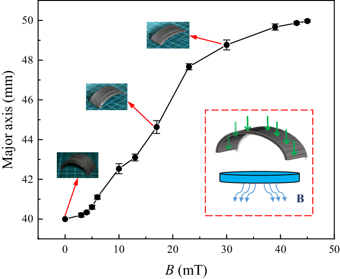
The experiment shows that the semi-circular arch can be transformed into the semi-elliptical shape owing to the action of the magnetic actuator. The relationship between the length of the elliptical shape and the magnetic density is demonstrated in Fig. 20. When the arch-shaped robot is fully extended under the magnetic flux density with the value of 45 mT, the length of its major axis reaches 50 mm. Notably, the friction between the robot and the baseplate during the experiments has some certain influence on the final deformation, which is reflected in the beginning stage of the curve.
The relationship between the magnetic field and the length of major axis, where the semi-circular arch is deformed under the action of the magnetic field.

6. Conclusions
In summary, we have performed a comprehensive study on the fabrication of soft magnetic robots with various geometric shapes and on exploring their locomotion mechanism under the action of magnetic fields. First, the material of the robot has been created by the complete materials preparation procedures of magnetic soft robots whose matrix is the mixture of silicone gels and NdFeB powders. The magnetic actuation principles including the magnetic force, the torque and the finite element framework were illustrated for analysing the locomotion mechanism. Then the triangular robot with the above-mentioned method was fabricated, and its two main locomotion patterns, that is, moving and warping, were fully explored in the experiment. The simulation result on the deformation behaviour agrees well with the dimensional analysis and experimental result, providing a universal and powerful method for the fabrication and analysis process. In addition, we generated the geometric-based strategy to fabricate other robots with various shapes, including the cross-shape, square, pentagram and arch, and their corresponding locomotion mechanisms were discussed in order.
The results cast new light on engineering soft robots under the multi-fields, which can certainly broaden the eyes on inventing intellectual devices and equipment.
Author contributions
Yuchen Jin, Shiyang Liu and Jianlin Liu conceived and designed the study. Jing Li and Gongqi Cao conducted data gathering. Yuchen Jin and Jianlin Liu performed statistical analyses. Yuchen Jin, Shiyang Liu and Jianlin Liu wrote the article.
Financial support
This work was supported by the National Natural Science Foundation (11972375, 12211530028), the Natural Science Foundation of Shandong Province (ZR202011050038) and the Science and Technology Project in Qingdao Developing Zone (2020-81).
Supplementary material
To view supplementary material for this article, please visit https://doi.org/S0263574722001631
Conflicts of interest
The authors declare no conflict of interest.
Ethical approval
Not applicable.