1. Introduction
The larger the aperture of an optical system, the stronger the light gathering ability and the higher the resolution. Therefore, modern optical systems are rapidly developing toward large aperture, high precision, high resolution, and high power [Reference Wu, Shen, Peng and Wu1]. As the final step in the manufacturing process of high-precision optical components, the polishing process is critical to improving the quality of the workpiece surface [Reference Pal, Kumar and Karar2]. Traditionally, the polishing process is done manually by skilled workers. Manual polishing is inefficient and the quality of the process is inconsistent [Reference Liang, Cui, Zhang, Meng, Ma, Li, Yu and Zhao3]. In order to improve polishing efficiency and accuracy, some computer numerically controlled (CNC) polishing systems have been developed to automate the polishing process [Reference Wang, Ke, Huang, Negi, Choi, Pullen, Kim, Zhu and Idir4]. However, CNC machine tools have a limited workspace, which results in lower polishing efficiency and limits the size of the workpiece [Reference Kakinuma, Igarashi, Katsura and Aoyama5].
In recent years, researchers have developed robots for optical mirror polishing that are cheaper, more flexible, and have a larger workspace than CNC machines [Reference Xu, Cheung, Wang and Zhao6]. Polishing optical mirrors by robots has become a trend. During the polishing processing, the robot end tool contacts the workpiece generating contact forces. Overloaded contact forces can cause damage to both the robot and the workpiece, and the magnitude of the contact force affects the polishing precision, which in turn affects the quality of the polishing [Reference Guo, Cheng, Wang and Li7]. Therefore, the amount of contact force must be controlled to improve the quality of the polishing.
When the robot performs polishing work, two different contact force control strategies can be classified according to the different forms of contact between the end polishing tool and the workpiece, i.e., rigid contact force control mode and compliant contact force control [Reference Liao, Xi and Liu8]. In the rigid contact force control mode, the contact force is controlled by the motion control system. Kamezaki et al. [Reference Kamezaki, Aoyama and Inasaki9] applied fuzzy theory to the motion control of a mold polishing robot and developed a robot system that automatically determines the normal direction of the polishing surface of an object mold. This robotic system can automatically polish under a certain press force, and stable force control was obtained. Nagata et al. [Reference Nagata, Hase, Haga, Omoto and Watanabe10] proposed a Computer Aided Design/Computer Aided Making-based position/force controller that can simultaneously achieve stable force control and accurate surface pickup feed control. The above methods belong to the rigid contact force control mode, which not only requires the establishment of an accurate mathematical model of the grinding tool and the workpiece but also needs to be accurately decoupled to control the driving force and position of each driving joint. Obviously, the modeling process of rigid contact force control is very complicated and not adaptable. Especially when there is a deviation between the grinding tool and the workpiece, it will generate a large force on the surface of the workpiece, which is very easy to damage the workpiece. Therefore, some compliant contact force control methods have been proposed.
In addition, some scholars have studied compliant contact force control methods. In compliant force control mode, the contact force is provided by a separate control mechanism mounted at the end of the robot, and the robot is used only for positioning, thus avoiding the coupling between position and force. Compliant contact force control consists of active and passive compliant control. Passive compliant contact force control is to install a suitable elastic mechanism [Reference Liu, Chen and Huang11] at the front end of the tool, so that the end tool and the workpiece contact with a certain cushioning effect, to achieve compliant control. Shahinian et al. [Reference Shahinian, Cherukuri and Mullany12] proposed a fiber-based tool that can adapt to different workpiece surface curvatures such as spherical and free-form surfaces. It was experimentally demonstrated that the removal rate of the tool can be predicted by Preston’s equation. Wei et al. [Reference Wei and Xu13] proposed a robotic polishing end-effector based on a constant force mechanism, where the constant force range of motion serves as a cushion to counteract excessive displacement due to inertia. Chaves-Jacob et al. [Reference Chaves-Jacob, Linares and Sprauel14] used a flexible tool to obtain smooth joint contact force and tool position. As the machine tool is used to control position rather than force, this reduces tool wear and stabilizes radial force in the pre-polishing process. Passive compliant force controls can be set to high stiffness for fast response rates and are inexpensive. However, it is not possible to actively adjust the magnitude of the contact force especially when the geometry of the workpiece varies significantly and can only maintain a low accuracy contact force over a short range. The contact force of the active compliant contact force control mode, on the other hand, is regulated by the sensors, control system, and end-effector, which ensures that the robot actively adapts to the changes in the machined surface and achieves a high-precision contact force. Mohammed et al. [Reference Mohammad, Hong and Wang15] proposed a linear hollow voice coil actuator for automated polishing process by integrating a force sensor that measures the polishing force and feeds it back to the controller, so that it can be adjusted according to the requirements of the polishing pre-planning. Experimental results show that the device achieves a good force tracking. Jin et al. [Reference Jin, Ji, Pan, Ao and Han16] applied the coupled contact force model to the airbag polishing contact force control system by using the BP neural network proportional–integral–derivative (PID) control strategy, realizing the online control of the polishing contact force. Therefore, to carry out active compliance control of the polishing contact force, an appropriate end-effector configuration must be selected first.
To achieve active compliant control of the polishing contact force, a suitable end-effector configuration should be selected. Currently, end-effectors with pneumatic actuators are a good choice for providing polishing force due to easy maintenance and nice natural air compliance. Zhou et al. [Reference Zhou, Zhang, Fan, Zhao and Gao17] proposed an online tuning neural PID controller to improve the force control performance of a pneumatic servo-polishing system. Real-time experimental results of polishing force control show that the proposed neural PID controller achieves excellent control performance regardless of whether the reference force is constant or varying. Dai et al. [Reference Dai, Li, Ji, Sun and Zhao18] introduced a pneumatic compliant polishing end-effector and proposed an inverse-stepping + PID force control strategy that achieves a continuous and stable output of the polishing force. Liao et al. [Reference Liao, Xi and Liu19] utilized an active pneumatic compliant tool head, built a recursive least squares estimator to estimate the pneumatic model, and designed a self-tuning controller using the least-degree pole placement method to achieve a constant polishing force. These controllers have nice performance in constant contact force control with pneumatic system. However, the polishing of optical mirrors is a complex process, and the environmental stiffness changes all the time, which leads to a steady-state error in the contact force. Therefore, it is necessary to propose an active compliant force controller, which can adapt to the change of environmental stiffness for the pneumatic polishing actuator.
Based on a 5 degrees of freedom (DOF) hybrid pneumatic servo-polishing robot in the context of optical mirror polishing, an active compliant force control method capable of adapting to changes in environmental stiffness is proposed, i.e., variable environmental stiffness adaptive impedance control. In order to ensure constant contact force, the causes of impedance control steady-state error are analyzed theoretically, and the calculation method of impedance control steady-state error is deduced. Then, an indirect adaptive impedance controller is designed to estimate the environmental stiffness and position online, so as to calculate the desired target position in real time, and finally realize the tracking of the polishing contact force. The effectiveness of the proposed method is verified through simulations and experiments.
The rest of this thesis is organized as follows. In Section 2, the mathematical model of the pneumatic servo-polishing control system is established. In Section 3, the causes of impedance control steady-state error are analyzed, and an indirect adaptive impedance controller is designed based on Lyapunov Stability Principle. The simulations of variable environmental stiffness and variable-desired polishing contact force are carried out. Experiments are carried out and the results are given in Section 4. Finally, some conclusions and prospects are given in Section 5.
2. Modeling of pneumatic servo-polishing control system
Pneumatic transmission technology can achieve compliance control by using the compressibility of the gas. Accordingly, a pneumatic servo-polishing control system at the end of the robot is set up in this study to realize constant force and compliance control in the polishing process.
2.1. The optical mirror processing robot
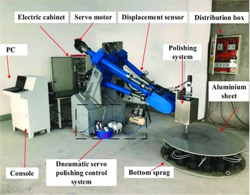
There are 5 degrees of freedom in the optical mirror processing robot designed in this study, and the robot is presented in Fig. 1. The parallel module is in the structure of 3UPS-UP. On the moving platform of the parallel module, the 2-DOF serial manipulator consists of the first-stage rotor, the second-stage rotor, and the end polishing tool. The control system includes a personal computer, an isochronous media access controller (IMAC), a servo motor and its driver, a control circuit, and various sensors.
The optical mirror processing robot.

2.2. Pneumatic servo-polishing control system
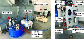
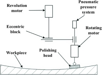
The arrangement of the pneumatic servo-polishing control system is shown in Fig. 2. The polishing tool system on the front end of the robot is of the double rotor planetary structure, and its structure is depicted in Fig. 3. The rotary movement of the polishing head is accomplished by the revolution motor and the rotation motor. The rotating motor is located in the rotation frame and is connected to the polishing head through the processing shaft. The pneumatic pressure system is connected on both sides so that the polishing head can move to a certain extent in the axial direction of the rotating motor. There is a certain distance between the axes of the revolution motor and the rotating motor, and the distance can be adjusted by an eccentric block. The rotating motor is connected to the eccentric block to drive the equipment to rotate, and the rotating motor drives the polishing head to rotate. At the same time, the constant force polishing is realized under the control of the pneumatic pressure system.
Pneumatic servo-polishing control system.

Structure of double rotor planetary polishing system.

2.3. Working principle of pneumatic servo-polishing control system
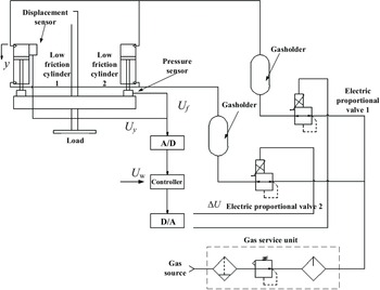
The schematic diagram of the whole pneumatic servo-polishing control system is illustrated in Fig. 4. It can be seen from Fig. 4 that a desired force output control signal U
w is set to control the opening size of the electric proportional valve, so that the gas produced by the gas compressor enters the cavity of the low-pressure friction cylinder through the storage tank. Thus, the cylinder piston rod is controlled to move to produce output force
 $F_{\mathrm{p}}$
. The output force
 $F_{\mathrm{p}}$
is measured by the force sensor at the front end of the cylinder, and its feedback signal is U
f
.
Schematic diagram of pneumatic servo-polishing control system.

a and b denote the corresponding upper and lower cavities of the cylinder, respectively. P, V, and A represent the gas pressure, volume, and force cross-sectional area in the chambers, respectively. X is the spore displacement of the electric proportional valve, and y represents the displacement of the piston rod.
Assume the gas is ideal, when the gas enters cavity a of the cylinder, the gas mass flow rate is
 \begin{equation} q_{m,\mathrm{a}}=\frac{\mathrm{d}m_{\mathrm{a}}}{\mathrm{d}t}=\frac{\mathrm{d}\!\left(\rho _{\mathrm{a}}V_{\mathrm{a}}\right)}{\mathrm{d}t}=\frac{V_{\mathrm{a}}}{T_{\mathrm{a}}R_{\mathrm{c}}}\!\left(\frac{\mathrm{d}P_{\mathrm{a}}}{\mathrm{d}t}+\frac{P_{\mathrm{a}}}{V_{\mathrm{a}}}\frac{\mathrm{d}V_{\mathrm{a}}}{\mathrm{d}t}-\frac{P_{\mathrm{a}}}{T_{\mathrm{a}}}\frac{\mathrm{d}T_{\mathrm{a}}}{\mathrm{d}t}\right) \end{equation}
where
 $m_{\mathrm{a}}$
is the gas mass in cavity a;
 $V_{\mathrm{a}}$
is the gas volume in cavity a;
 $P_{\mathrm{a}}$
is the gas pressure in the cylinder;
 $\rho _{\mathrm{a}}$
is the gas density;
 $R_{\mathrm{c}}$
is the ideal gas constant; and
 $T_{\mathrm{a}}$
is the thermodynamic temperature of the gas in cavity a.
The gas flow process is assumed to be isentropic and adiabatic. The following equation can be obtained:
 \begin{equation} q_{m,\mathrm{a}}=\frac{1}{R_{\mathrm{c}}T_{\mathrm{a}}}\!\left[\frac{V_{\mathrm{a}}}{k}\frac{\mathrm{d}P_{\mathrm{a}}}{\mathrm{d}t}+P_{\mathrm{a}}\frac{\mathrm{d}V_{\mathrm{a}}}{\mathrm{d}t}\right] \end{equation}
where k is the adiabatic exponent, k = 1.4.
According to the previous hypotheses, the flow process of gas in the gas-guide tube is described by the Sanville flow equation, and the valve flow equation is indicated in Eq. (3):
 \begin{equation} q_{m}=\frac{C_{\mathrm{d}}S\!\left(x\right)}{\sqrt{T}}P_{\mathrm{u}}\sqrt{\frac{k}{R_{\mathrm{c}}}\!\left(\frac{2}{k+1}\right)^{\frac{k+1}{k-1}}} \end{equation}
where
 $C_{\mathrm{d}}$
is the flow coefficient of the throttle port of the proportional valve, and
 $C_{\mathrm{d}}=0.628$
; S is the effective cross-sectional area of the valve port; T is the absolute temperature;
 $P_{\mathrm{u}}$
is the absolute pressure of the gas inlet of the electric proportional valve; and
 $R_{\mathrm{c}}$
is the ideal gas constant.
The gas mass flow rate through the spool valve is only a function of the spool displacement X and the output pressure
 $P_{\mathrm{d}}$
, i.e.:
 \begin{equation} q_{m}=f\!\left(X,P_{\mathrm{d}}\right) \end{equation}
Linearization of Eq. (7) around the zero position yields:
 \begin{equation} \Delta q_{m}=K_{1}\Delta X+K_{2}\Delta P_{\mathrm{d}} \end{equation}
where
 $K_{1}=\dfrac{\partial q_{m}}{\partial X}|_{X=0}, K_{2}=\dfrac{\partial q_{m}}{\partial P_{\mathrm{d}}}|_{{P_{\mathrm{d}}}=0}$
.
The gas output from the electric proportional valve will pass through a gas-guide tube of length L into cavity a. Assuming that gas flows in an ideal circular pipeline in the form of laminar flow, ignoring the flow loss at each connection, Anderson’s theory can be obtained as follows:
 \begin{equation} \left\{\begin{array}{l} q_{m,\mathrm{a}}=K_{3}\!\left(P_{s}-P_{\mathrm{a}}\right)\\[4pt] \Delta q_{m,\mathrm{a}}=K_{3}\!\left(\Delta P_{s}-\Delta P_{\mathrm{a}}\right) \end{array}\right. \end{equation}
where
 $K_{3}=\rho _{\mathrm{av}}d_{2}^{2}A_{\mathrm{g}}/(32\mu L) ;\, q_{m,\mathrm{a}}$
is the mass flow rate of gas in the gas-guide tube;
 $\rho _{\mathrm{av}}$
is the gas density;
 $d_{2}$
is the diameter of gas-guide tube;
 $\mu$
is the viscosity coefficient of gas;
 $A_{\mathrm{g}}$
is the radial cross-sectional area of gas-guide;
 $P_{s}$
is the inlet pressure of the gas-guide tube; and
 $P_{\mathrm{a}}$
is the outlet pressure of the gas-guide tube.
2.4. Analysis of cylinder force system
In the pneumatic servo-polishing control system, the polishing force is controlled by the movement of the cylinder piston rod, and the movement position in space is completed by the hybrid robot. In the case of high positioning accuracy of the hybrid robot, the polishing tool is always in contact with the surface of the workpiece, and the volume change in the cylinder cavity is tiny. Therefore, in the actual polishing process, the flow rate change caused by the volume change in the cavity can be ignored, and Eq. (5) is simplified as follows:
 \begin{equation} q_{m,\mathrm{a}}=\frac{1}{k}\frac{V}{R_{\mathrm{c}}T_{\mathrm{a}}}\frac{\mathrm{d}P_{\mathrm{a}}}{\mathrm{d}t} \end{equation}
The Laplace transformations of Eqs. (5), (6), and (7), respectively, are combined to give:
 \begin{equation} \frac{P_{\mathrm{a}}\!\left(s\right)}{X\!\left(s\right)}=\frac{K_{1}}{\frac{\left(K_{3}-K_{2}\right)V_{\mathrm{a}}}{kT_{\mathrm{a}}R_{\mathrm{c}}K_{3}}s-K_{2}} \end{equation}
Equation (8) can be simplified by
 $K_{2}=0$
as follows:
 \begin{equation} \frac{P_{\mathrm{a}}\!\left(s\right)}{X\!\left(s\right)}=\frac{kT_{\mathrm{a}}R_{\mathrm{c}}K_{1}}{V_{\mathrm{a}}s} \end{equation}
As illustrated in Fig. 5, it is the force analysis diagram of the cylinder piston. The piston rod and the polishing disc are regarded as a whole. Since the two sides are symmetrical structures, the force balance equation of a single cylinder can be written in the ideal state as follows:
 \begin{equation} M\frac{\mathrm{d}^{2}y}{\mathrm{d}t^{2}}+f\frac{\mathrm{d}y}{\mathrm{d}t}+F_{f}+\frac{F_{\mathrm{p}}}{2}=P_{\mathrm{a}}A_{\mathrm{a}}-P_{\mathrm{b}}A_{\mathrm{b}} \end{equation}
where M is the total mass of the piston and load; f is the viscous damping coefficient of the system; y is the displacement of the cylinder piston rod;
 $F_{f}$
is the friction force in the cylinder;
 $F_{\mathrm{p}}$
is the polishing force of the system;
 $P_{\mathrm{a}}$
is the pressure of the upper cavity of the cylinder;
 $P_{\mathrm{b}}$
is the pressure of the lower cavity of the cylinder;
 $A_{\mathrm{a}}$
is the force area of the piston in the upper chamber of the cylinder; and
 $A_{\mathrm{b}}$
is the force area of the piston in the lower chamber of the cylinder.
Force analysis diagram of the cylinder piston.

 $P_{\mathrm{b}}A_{\mathrm{b}}$
in the above equation is to balance the gravity of the front end polishing tool. Hence, Eq. (10) is rewritten into the incremental form, and the Laplace transformation is carried out to obtain:
 \begin{equation} Ms^{2}Y\!\left(s\right)+fsY\!\left(s\right)+F_{f}\!\left(s\right)+0.5F_{\mathrm{p}}\!\left(s\right)=P_{\mathrm{a}}\!\left(s\right)A_{\mathrm{a}} \end{equation}
After simplified analysis, the transfer function of cylinder piston rod displacement
 $Y(\mathrm{s})$
and cavity pressure
 $P_{\mathrm{a}}(s)$
can be obtained:
 \begin{equation} \frac{Y\!\left(\mathrm{s}\right)}{P_{\mathrm{a}}\!\left(\mathrm{s}\right)}=\frac{A_{\mathrm{a}}}{Ms^{2}+fs+0.5K_{\mathrm{p}}} \end{equation}
where
 $K_{\mathrm{p}}$
is the equivalent spring stiffness coefficient.
The spore displacement
 $X(s)$
and control voltage
 $U_{\mathrm{w}}(s)$
of the electric proportional valve can be treated as proportional links, that is,
 $X(s)/U_{\mathrm{w}}(s)=K_{\mathrm{d}}$
. Therefore, the transfer functions between cylinder piston rod displacement
 $Y(s)$
, polishing contact force
 $F_{\mathrm{p}}(s)$
, and control voltage
 $U_{\mathrm{w}}(s)$
of electric proportional valve can be obtained, respectively:
 \begin{equation} \frac{Y\!\left(s\right)}{U_{\mathrm{w}}\!\left(s\right)}=K_{\mathrm{d}}\frac{Y\!\left(s\right)}{P_{\mathrm{a}}\!\left(s\right)}\cdot \frac{P_{\mathrm{a}}\!\left(s\right)}{X\!\left(s\right)}=\frac{K_{\mathrm{d}}A_{\mathrm{a}}kT_{\mathrm{a}}R_{\mathrm{c}}K_{1}}{V_{\mathrm{a}}s\!\left(Ms^{2}+fs+0.5K_{\mathrm{p}}\right)} \end{equation}
 \begin{equation} \frac{F_{\mathrm{p}}\!\left(s\right)}{U_{\mathrm{w}}\!\left(s\right)}=K_{\mathrm{d}}K_{\mathrm{p}}\frac{Y\!\left(s\right)}{P_{\mathrm{a}}\!\left(s\right)}\cdot \frac{P_{\mathrm{a}}\!\left(s\right)}{X\!\left(s\right)}=\frac{K_{\mathrm{d}}K_{\mathrm{p}}A_{\mathrm{a}}kT_{\mathrm{a}}R_{\mathrm{c}}K_{1}}{V_{\mathrm{a}}s\!\left(Ms^{2}+fs+0.5K_{\mathrm{p}}\right)} \end{equation}
where
 $K_{\mathrm{d}}$
is the gain of the electric proportional valve.
2.5. Mathematical model of this experimental system
The final control model can be obtained by substituting the specific parameter values of each element in the pneumatic servo-polishing control system into the corresponding calculation equation. The specific parameters are listed in Table I.
Parameters of the pneumatic servo system.

In the initial working state of the system, gas is injected into the upper chamber of the cylinder, and the piston is located at the bottom of the cylinder, that is, the displacement of the piston rod y is 30 mm. The length of the gas pipe connecting the cylinder and the proportional valve in Eq. (6) is known to be L = 100 mm. Hence,
 $K_{1}=58, A_{\mathrm{a}}=3.142\times 10^{-4}\mathrm{m}^{2}, V_{\mathrm{a}}=1.445\times 10^{-5}\mathrm{m}^{3}, Y(s)/U(s)=12245.96/(s^{3}+33.33s^{2}+2083.33s)$
.
3. Research on robot polishing compliance control strategy
The optical mirror processing robot has a high requirement for precision and the passive compliance control cannot meet the needs. Therefore, the active compliance control strategy is adopted. In this section, a position-based impedance control strategy in active compliance control is selected to realize constant force polishing of the optical mirror processing robot.
3.1. Position-based impedance control strategy
A commonly used impedance control expression is
 \begin{equation} m_{\mathrm{d}}\!\left(\ddot{y}_{\mathrm{r}}-\ddot{y}_{\mathrm{d}}\right)+b_{\mathrm{d}}\!\left(\dot{y}_{\mathrm{r}}-\dot{y}_{\mathrm{d}}\right)+k_{\mathrm{d}}\!\left(y_{\mathrm{r}}-y_{\mathrm{d}}\right)=-f_{\mathrm{e}} \end{equation}
where
 $m_{\mathrm{d}}, b_{\mathrm{d}}$
, and
 $k_{\mathrm{d}}$
represent the target inertia matrix, damping matrix, and stiffness matrix, respectively.
 $y_{\mathrm{r}}, \dot{y}_{\mathrm{r}}$
, and
 $\ddot{y}_{\mathrm{r}}$
are the desired position, velocity, and acceleration of the end-polishing tool, respectively.
 $y_{\mathrm{d}}, \dot{y}_{\mathrm{d}}$
, and
 $\ddot{y}_{\mathrm{d}}$
denote the target position, velocity, and acceleration of the end polishing tool, respectively.
 $f_{\mathrm{e}}$
represents the contact force generated by the end polishing tool in the process of polishing the workpiece.
In the actual polishing operation, the one on the left of Eq. (15) is commonly used
 $e=f_{\mathrm{d}}-f_{\mathrm{e}}$
to replace, where
 $f_{\mathrm{d}}$
represents the desired polishing contact force. Actual contact force
 $f_{\mathrm{e}}$
is monitored in real time by the force sensor installed between the flange and the cylinder.
The position correction is
 $y_{f}=y_{\mathrm{r}}-y_{\mathrm{d}}$
. Hence, Eq. (15) can be redefined as:
 \begin{equation} m_{\mathrm{d}}\ddot{y}_{f}+b_{\mathrm{d}}\dot{y}_{f}+k_{\mathrm{d}}y_{f}=-f_{\mathrm{e}} \end{equation}
Equation (16) in the frequency domain can be expressed as:
 \begin{equation} y_{f}\!\left(s\right)=\frac{-f_{\mathrm{e}}\!\left(s\right)}{m_{\mathrm{d}}s^{2}+b_{\mathrm{d}}s+k_{\mathrm{d}}} \end{equation}
According to Eq. (17), the impedance controller is a typical second-order system model. To facilitate the study, the transfer function of the system under the condition of a single degree of freedom is written as follows:
 \begin{equation} G\!\left(s\right)=\frac{y_{f}\!\left(s\right)}{f_{\mathrm{e}}\!\left(s\right)}=\frac{-1}{m_{\mathrm{d}}s^{2}+b_{\mathrm{d}}s+k_{\mathrm{d}}} \end{equation}
 \begin{equation} \left\{\begin{array}{l} \omega _{n}=\sqrt{\frac{k_{\mathrm{d}}}{m_{\mathrm{d}}}}\\[9pt] \xi =\dfrac{b_{\mathrm{d}}}{2\sqrt{m_{\mathrm{d}}k_{\mathrm{d}}}} \end{array}\right. \end{equation}
where
 $\omega _{n}$
is the natural frequency of the system;
 $\xi$
is the system damping ratio.
In impedance control mode, the selection of target impedance parameters affects the control of polishing force directly. Reasonable impedance parameters not only improve the robustness of the system but also ensure a good polishing effect. Target impedance parameters include ideal target inertia
 $m_{\mathrm{d}}$
, ideal target damping
 $b_{\mathrm{d}}$
, and ideal target stiffness coefficient
 $k_{\mathrm{d}}$
.
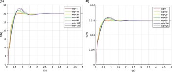
The response curves of changing target inertia coefficient
 $m_{\mathrm{d}}$
. (a) Force response curves. (b) Position response curves.

3.2. Characteristic analysis of impedance parameters
According to the transfer function of the pneumatic servo-polishing control system obtained in Section 3.1, the simulation model of the impedance control system is constructed. Considering the size of the robot, the target position of the cylinder piston rod is set as
 $Y_{\mathrm{d}}=0.01\,\mathrm{m}$
. Generally, the contact force should be no more than 50 N. Thus, we set the desired polishing contact force as
 $F_{\mathrm{d}}=30\,\mathrm{N}$
. Considering the external environment characteristic of the robot, the environmental stiffness is set as
 $K_{\mathrm{e}}=3000\,\mathrm{N}/\mathrm{m}$
. Three target impedance parameters,
 $m_{\mathrm{d}}, b_{\mathrm{d}}$
, and
 $k_{\mathrm{d}}$
, are studied by using the control variable method, and the influence of one parameter on the control system is analyzed according to the simulation diagram generated.
3.2.1. Influence of target inertia coefficient on control effect
In the impedance control system,
 $b_{\mathrm{d}}$
and
 $k_{\mathrm{d}}$
are set as constants, and
 $m_{\mathrm{d}}$
as variables.
 $b_{\mathrm{d}}=1000, k_{\mathrm{d}}=1$
. By adjusting the value of
 $m_{\mathrm{d}}$
, the simulation curves of the polishing force and the desired position of the cylinder piston rod changed over time are illustrated in Fig. 6. It can be seen from the simulation results that
 $m_{\mathrm{d}}$
reflects the acceleration term of the whole pneumatic polishing system, and the overall mass of the pneumatic polishing system affects the impact force generated between the end tool and the workpiece directly. The less the mass, the lighter the inertial shock generated, the faster the system response and the faster it can reach a smooth state, and vice versa. Therefore, when selecting the target inertia coefficient, the actual mass of the whole pneumatic servo-polishing control system should be taken as a reference, so as not to produce excessive deviation.
3.2.2. Influence of target damping coefficient on control effect
In the impedance control system,
 $m_{\mathrm{d}}$
= 20,
 $k_{\mathrm{d}}$
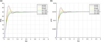
= 1. As depicted in Fig. 7, simulation curves of the polishing force and the desired position of the cylinder piston rod change over time by varying the value of
 $b_{\mathrm{d}}$
. The overshoot and response speed of the system are related to the value of
 $b_{\mathrm{d}}$
, and the steady-state error will not be generated when the system tends to be stable. When the value of
 $b_{\mathrm{d}}$
is low, the fluctuation range of the system is wide near the steady-state value, and it takes a longer time to reach the stable state. With the gradual increase of
 $b_{\mathrm{d}}$
value, the overshoot of the system is significantly reduced, the overall fluctuation range is significantly reduced, and it can reach a stable state quickly. When there is no overshoot in the system response, if
 $b_{\mathrm{d}}$
continues to increase, the time of the system response will increase. Therefore, the environmental characteristics of the polishing system should be taken into account when selecting
 $b_{\mathrm{d}}$
, so that it can achieve an ideal polishing effect.
The response curves of changing target damping coefficient
 $b_{\mathrm{d}}$
. (a) Force response curves. (b) Position response curves.

3.2.3. The influence of the target stiffness coefficient on the control
In the impedance control system,
 $m_{\mathrm{d}}$
and
 $b_{\mathrm{d}}$
are set as constants,
 $k_{\mathrm{d}}$
as variables.
 $m_{\mathrm{d}}$
= 20 and
 $b_{\mathrm{d}}$
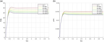
= 1000. As shown in Fig. 8, by changing the value of
 $k_{\mathrm{d}}$
, the simulation curves of the desired polishing force and the desired position of the cylinder piston rod changed over time. It can be seen from the simulation results that the steady-state error exists in the system, and the steady-state values of the response curves of force and position decrease with the increase of
 $k_{\mathrm{d}}$
. As the environmental stiffness of the workpiece increases, the more difficult the downward displacement of the cylinder piston rod will be, and the lower the value of
 $y_{\mathrm{d}}$
will be, thus generating force errors and position errors. It can be seen that the contact form between the end tool and the workpiece can be determined by setting the value of
 $k_{\mathrm{d}}$
. Therefore, selecting an appropriate target stiffness coefficient can ensure a relatively constant desired contact force and achieve a good polishing effect.
The response curves of changing target stiffness coefficient
 $k_{\mathrm{d}}$
. (a) Force response curves. (b) Position response curves.

From the above simulation analysis, it can be concluded that the target impedance parameters
 $m_{\mathrm{d}}, b_{\mathrm{d}}, k_{\mathrm{d}}$
all have a corresponding impact on the system. It means that appropriate parameters should be selected according to the actual situation of the end polishing tool system, before the polishing operation.
3.3. Study on the steady-state error of impedance control
The steady-state error of a control system is a measure of the system’s control accuracy, which is called steady-state performance. It can be seen from the simulation diagram in Section 3.2 that neither the target inertia coefficient nor the target damping coefficient produces steady-state errors, while the steady-state errors of the system are eventually formed by different target stiffness coefficients
 $k_{\mathrm{d}}$
, indicating that
 $k_{\mathrm{d}}$
is an important cause of steady-state errors. The problem is simplified as the case of a single degree of freedom:
 \begin{equation} m_{\mathrm{d}}\ddot{y}_{\mathrm{r}}+b_{\mathrm{d}}\dot{y}_{\mathrm{r}}+k_{\mathrm{d}}\!\left(y_{\mathrm{r}}-y_{\mathrm{d}}\right)=-F_{\mathrm{e}} \end{equation}
where
 $F_{\mathrm{e}}$
represents the polishing contact force between the end grinding tool and the workpiece.
The environment model adopts the equation
 $F_{\mathrm{e}}=k_{\mathrm{e}}(y_{\mathrm{r}}-y_{\mathrm{e}})$
, and the following equation can be obtained:
 \begin{equation} m_{\mathrm{d}}\!\left(\ddot{F}_{\mathrm{d}}-\ddot{E}\right)+b_{\mathrm{d}}\!\left(\dot{F}_{\mathrm{d}}-\dot{E}\right)+k_{\mathrm{d}}\!\left(F_{\mathrm{d}}-E\right)=\left(E-F_{\mathrm{d}}\right)k_{\mathrm{e}}+k_{\mathrm{d}}k_{\mathrm{e}}\!\left(y_{\mathrm{d}}-y_{\mathrm{e}}\right) \end{equation}
where
 $E=F_{\mathrm{d}}-F_{\mathrm{e}}, k_{\mathrm{e}}$
is the environmental stiffness coefficient, and
 $y_{\mathrm{e}}$
is the environmental position.
When the system tends to be stable,
 $\ddot{F}_{\mathrm{d}}=\dot{F}_{\mathrm{d}}=0, \ddot{E}=\dot{E}=0$
. Hence, the steady-state error model of the system is obtained:
 \begin{equation} E_{\mathrm{ss}}=F_{\mathrm{d}}-\frac{k_{\mathrm{d}}k_{\mathrm{e}}}{k_{\mathrm{d}}+k_{\mathrm{e}}}\!\left(y_{\mathrm{d}}-y_{\mathrm{e}}\right) \end{equation}
 \begin{equation} F_{\mathrm{ss}}=\frac{k_{\mathrm{d}}k_{\mathrm{e}}}{k_{\mathrm{d}}+k_{e}}\!\left(y_{\mathrm{d}}-y_{\mathrm{e}}\right) \end{equation}
According to Eq. (23), the system polishing contact force
 $F_{\text{ss}}$
is composed of
 $k_{\mathrm{d}}, k_{\mathrm{e}}, y_{\mathrm{d}}$
, and
 $y_{\mathrm{e}}$
.
 $k_{\mathrm{d}}$
is an artificial quantity, while
 $k_{\mathrm{e}}$
and
 $y_{\mathrm{e}}$
are unknown quantities.
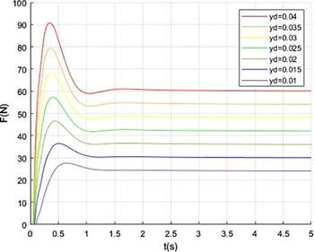
As can be seen in Fig. 9, it is the force response curves of
 $y_{\mathrm{d}}$
when
 $y_{\mathrm{e}} = 0.005 $
m,
 $k_{\mathrm{e}}=3000$
N/m, and
 $k_{\mathrm{d}}$
= 2000 N/m.
The force response curves of changing target position
 $y_{\mathrm{d}}$
.

In general, when polishing the workpiece, the environmental stiffness value is very high. However, any deviation of the environmental position may cause a great impact, which is not conducive to the processing of the workpiece. Therefore, to reduce or eliminate the steady-state error of the polishing contact force of the system, set
 $E_{\mathrm{ss}}=0$
, then:
 \begin{equation} y_{\mathrm{d}}=\frac{\left(k_{\mathrm{d}}+k_{\mathrm{e}}\right)F_{\mathrm{d}}}{k_{\mathrm{d}}k_{\mathrm{e}}}+y_{\mathrm{e}} \end{equation}
According to the analysis of Fig. 9 and Eq. (24), in the ordinary impedance control mentioned above, the artificially set target position is different; thus, the polishing contact force when the system reaches stability is also different. Set
 $k_{\mathrm{eq}}=k_{\mathrm{d}}k_{\mathrm{e}}/(k_{\mathrm{d}}+k_{\mathrm{e}})$
, only when
 $y_{\mathrm{d}}=F_{\mathrm{d}}/k_{\mathrm{eq}}+y_{\mathrm{e}}$
is satisfied, the polishing contact force between the end polishing tool and the workpiece can accurately track the desired contact force. However, the actual situation is that the
 $k_{\mathrm{eq}}$
and
 $y_{\mathrm{e}}$
are unknown, and it is very difficult to measure in real time. Therefore, the adaptive impedance control is studied to estimate the value of the
 $k_{\mathrm{eq}}$
and
 $y_{\mathrm{e}}$
online, so as to reduce the steady-state error and realize the purpose of polishing contact force tracking.
3.4. Design of indirect adaptive controller
To eliminate the steady-state errors of the system affected by environmental stiffness and position mentioned above, an indirect adaptive controller is designed in this section to carry out an online estimation of
 $k_{\mathrm{e}}$
and
 $y_{\mathrm{e}}$
. In this model,
 $y_{\mathrm{d}}$
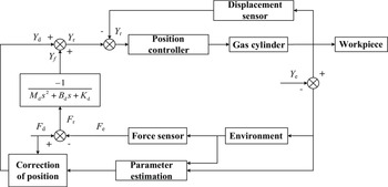
is calculated in real time, and the polishing contact force tracking is realized finally. Figure 10 shows the principle diagram of the adaptive impedance control system.
Schematic diagram of the adaptive impedance control system.

When the steady-state error of the system
 $E_{\mathrm{ss}}\rightarrow 0$
and both
 $k_{\mathrm{e}}$
and
 $y_{\mathrm{e}}$
are known quantities, the desired target position can be calculated as:
 \begin{equation} y_{\mathrm{d}}=\frac{F_{\mathrm{d}}}{\hat{k}_{\mathrm{e}}}+\hat{y}_{\mathrm{e}} \end{equation}
where
 $\hat{y}_{\mathrm{e}}$
represents the estimated value of
 $y_{\mathrm{e}}$
, and
 $\hat{k}_{\mathrm{e}}$
represents the estimated value of
 $k_{\mathrm{e}}$
.
The indirect adaptive algorithm is used to calculate
 $\hat{y}_{\mathrm{e}}$
and
 $\hat{k}_{\mathrm{e}}$
. Setup parameter
 $\varphi _{k}=\hat{k}_{\mathrm{e}}-k_{\mathrm{e}}, \varphi _{y}=\hat{k}_{\mathrm{e}}\hat{y}_{\mathrm{e}}-k_{\mathrm{e}}y_{\mathrm{e}}, \varphi =[\begin{array}{l@{\quad}l} \varphi _{k} & \varphi _{y} \end{array}]^{\mathrm{T}}$
. The following equation can be obtained:
 \begin{equation} \hat{F}_{\mathrm{e}}-F_{\mathrm{e}}=\left[\begin{array}{l@{\quad}l} y & -1 \end{array}\right]\varphi \end{equation}
where
 $\hat{F}_{\mathrm{e}}$
represents the estimated value of the polishing contact force
 $F_{\mathrm{e}}$
.
To ensure that
 $\hat{F}_{\mathrm{e}}\rightarrow F_{\mathrm{e}}$
converges to
 $F_{\mathrm{e}}\rightarrow F_{\mathrm{d}}$
, the Lyapunov Stability Principle is adopted for analysis, and the expressions of
 $\hat{k}_{\mathrm{e}}\hat{y}_{\mathrm{e}}$
and
 $\hat{k}_{\mathrm{e}}$
are obtained.
In combination with Eq. (26) and based on
 $F_{\mathrm{e}}(\varphi,t)=0$
, it can be gotten that when
 $\varphi =[\begin{array}{l@{\quad}l} 0 & 0 \end{array}]^{\mathrm{T}}$
, the system is in unique equilibrium, that is,
 $\varphi _{k}=0, \varphi _{y}=0$
. Thus, a positive definite Lyapunov energy function is written as follows:
 \begin{equation} V=\varphi ^{\mathrm{T}}\prod \varphi \end{equation}
where
 $\prod$
is a positive definite symmetric matrix of 2 × 2.
If the system equation of state parameter
 $\varphi$
is
 $\dot{\varphi }=-\prod ^{-1}[\begin{array}{l@{\quad}l} y & -1 \end{array}]^{\mathrm{T}}(\hat{F}_{\mathrm{e}}-F_{\mathrm{e}})$
, the first derivative of energy function V concerning time can be obtained by combining Eq. (26) and Eq. (27):
 \begin{equation} \dot{V}=2\varphi ^{\mathrm{T}}\prod \dot{\varphi }=-2\varphi ^{\mathrm{T}}\!\left[\begin{array}{l} y\\[4pt] -1 \end{array}\right]\left(\hat{F}_{\mathrm{e}}-F_{\mathrm{e}}\right)=-2\!\left(\hat{F}_{\mathrm{e}}-F_{\mathrm{e}}\right)^{2} \end{equation}
Let
 $\prod ^{-1}=\left[\begin{array}{l@{\quad}l} \eta _{1} & 0\\[4pt] 0 & \eta _{2} \end{array}\right], \eta _{1}$
and
 $\eta _{2}$
be positive constants of the positive definite matrix, then:
 \begin{equation} \left\{\begin{array}{l} \hat{k}_{\mathrm{e}}\!\left(t\right)=\hat{k}_{\mathrm{e}}\!\left(0\right)-\eta _{1}\int _{0}^{t}y\!\left(\hat{F}_{\mathrm{e}}-F_{\mathrm{e}}\right)\mathrm{d}t\\[8pt] \hat{y}_{\mathrm{e}}\!\left(t\right)=\hat{y}_{\mathrm{e}}\!\left(0\right)-\eta _{1}\int _{0}^{t}\dfrac{\left(\hat{F}_{\mathrm{e}}-F_{\mathrm{e}}\right)}{\hat{k}_{\mathrm{e}}}\!\left(y\hat{y}_{\mathrm{e}}+\frac{\eta _{2}}{\eta _{1}}\right)\mathrm{d}t\\[8pt] \hat{F}_{\mathrm{e}}=\hat{k}_{\mathrm{e}}\!\left(y-\hat{y}_{\mathrm{e}}\right) \end{array}\right. \end{equation}
The stiffness coefficient after the indirect adaptive control algorithm is
 $\hat{k}_{\mathrm{eq}}=k_{\mathrm{d}}\hat{k}_{\mathrm{e}}/(k_{\mathrm{d}}+\hat{k}_{\mathrm{e}})$
, and the desired output destination location is
 $y_{\mathrm{d}}=\hat{y}_{\mathrm{e}}+F_{\mathrm{d}}/\hat{k}_{\mathrm{e}}$
.
3.5. Simulation and comparison of different environmental stiffness coefficients
Through the study of the indirect adaptive impedance control algorithm, this section will build an adaptive impedance control simulation model according to the theoretical equation that has been derived. Simulation parameters are set as follows:
 $m_{\mathrm{d}}$
= 20,
 $b_{\mathrm{d}}$
= 2000,
 $k_{\mathrm{d}}$
= 6000,
 $\eta _{1}$
= 300,
 $\eta _{2}$
= 500,
 $\hat{k}_{\mathrm{e}}(0)$
= 3000,
 $\hat{y}_{\mathrm{e}}(0)$
= 0.005.
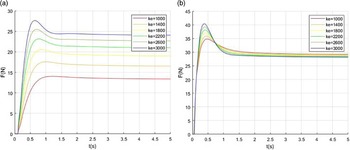
The tracking effect of normal impedance control and adaptive impedance control on desired polishing contact force of 30N under different environmental stiffness is shown in Fig. 11(a) and (b), respectively. According to the simulation results in Fig. 11(a), when
 $k_{\mathrm{e}}$
= 1000 N/m,
 $k_{\mathrm{e}}$
= 2000 N/m,
 $k_{\mathrm{e}}$
= 3000 N/m, there is an error between the contact force and the desired contact force when the normal impedance control reaches a steady state. On the basis of the previous analysis, the steady-state error
 $E_{\mathrm{ss}}$
of the system is related to
 $k_{\mathrm{eq}}$
, which is jointly determined by
 $k_{\mathrm{e}}$
and the
 $k_{\mathrm{d}}$
. According to the simulation results in Fig. 11(b), adaptive impedance control can accurately track the desired force under different environmental stiffness. As
 $k_{\mathrm{e}}$
increases from 1000 to 3000, the response speed of the curve becomes faster, but the overshoot of the system becomes larger. This is mainly because the impact of the tool at the moment of contact with the environment becomes stronger when the external environmental stiffness increases. Due to the change of environmental stiffness, the system will have a deviation when tracking the polishing contact force. This is because in the case of high environmental stiffness, even a slight change in the position of the cylinder piston rod will produce a great force error. However, from the simulation results, the indirect adaptive impedance control method has a better control effect for different environmental stiffness and can achieve accurate tracking of the polishing contact force.
Force response curves of different environmental stiffness coefficients
 $k_{\mathrm{e}}$
. (a) Ordinary impedance control. (b) Adaptive impedance control.

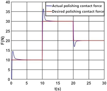
Simulation of tracking curves for variable desired polishing contact force.

3.6. Simulation of variable desired polishing contact force
The simulation of tracking curves for variable desired polishing contact force is visualized in Fig. 12. The initial desired polishing contact force is set as 10 N, increasing to 30 N at t = 10 s and decreasing to 20 N at t = 20 s. The initial desired polishing contact force is represented by the red line. The actual polishing contact force is represented by the blue line. In the whole simulation process, the desired polishing contact force increases first and then decreases. The actual polishing contact force accurately tracks the desired force in a short time, showing considerable robustness of the adaptive impedance control system.
4. Experimental research and analysis
In this section, the optical mirror processing robot contact force control experiments and the constant force polishing aluminum plate experiment are carried out. To control the polishing contact force, an adaptive impedance control method is written by calling the custom servo algorithm module in the IMAC control software first. Then, the expected contact force is set, according to the planned polishing trajectory, and the program to the IMAC controller for pneumatic control is downloaded. The actual displacement and contact force of the cylinder piston rod are measured and then calculated inside the IMAC controller. The obtained results of the calculation are controlled by the analog output outlet electrical proportional valve to output the corresponding air pressure. Then, the pressure generated by the cylinder pushing down the piston rod on the end tool is controlled, so that the actual contact force is constantly close to the expected contact force.
4.1. Experiments of robot contact force control
The robot contact force control experiments include the constant force contact experiment, variable desired force tracking experiment, and variable environmental stiffness contact force experiment.
4.1.1. Constant force contact experiment
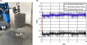
As shown in Fig. 13(a), before the polishing experiment, an inflatable gasbag is placed on the bottom supported aluminum plate. Then the robot end polishing tool is controlled to apply pressure to the gasbag, during which the end tool never left the surface of the gasbag. Notably, the gasbag is very fragile, and a slightly larger force might damage it. This experiment is designed to prove whether the adaptive impedance control is effective and whether the output polishing force of the cylinder can be accurately controlled. The experimental data of contact force are depicted in Fig. 13(b).
The experiment of constant force contact. (a) Field test drawing. (b) Contact force diagram.

The experimental results reach the desired target and the gasbag remained intact. As can be seen from Fig. 13(b), the fluctuation of the contact force is light after reaching stability, and the fluctuation range of the force error is ±0.8 N, which indicates that the control accuracy of the force is relatively high.
4.1.2. Variable desired force tracking experiment
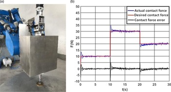
The purpose of this experiment is to prove that the adaptive impedance control algorithm can track the actual contact force well when the desired force changes. As indicated in Fig. 14(a), when polishing the aluminum plate, the initial desired polishing contact force is set at 10 N, which increases to 30 N when t = 10 s and decreases to 20 N when t = 20 s. Then, the experimental data of contact force in this process are extracted and drawn into a curve, as shown in Fig. 14(b).
The experiment of variable desired force tracking. (a) Field test drawing. (b) Variable desired force tracking graph.

It can be seen from Fig. 14(b) that the desired contact force changes abruptly when t = 10 s and t = 20 s. As for actual contact force overshoots, its rising time is about 0.2 s, and settling time is about 2 s. It shows that the adaptive impedance control algorithm can track the abrupt force quickly, achieving a satisfactory force tracking effect.
4.1.3. Contact force experiment with variable environmental stiffness
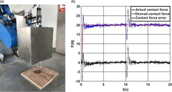
The purpose of this experiment is to demonstrate the adaptability of the adaptive impedance control algorithm to different external environments. The specific practice is presented in Fig. 15(a): first, the end polishing tool is controlled to apply pressure to the board; then the end is controlled to move right until it detaches off the board and presses down to contact the aluminum plate. Contact force experimental data of this process are extracted and plotted into a curve, as shown in Fig. 15(b).
The experiment of contact force with variable environmental stiffness. (a) Field test drawing. (b) The curves of contact force with variable environmental stiffness.

As can be seen from Fig. 15(b), at the beginning of contact with the board, the contact force of the system gradually becomes stable after a light shock. When the end polishing head is detached from the board, the polishing head is not in contact with the environment at this time, so the contact force decreased. Then, when the cylinder piston rod moves down and the polishing head contacts the aluminum plate, the system has a heavy shock, because the hardness of the aluminum plate is greater than the hardness of the wood. The system re-estimates the environmental stiffness and returns to a steady state within 1.5 s. The steady-state error can be kept within ±1 N. The experiment proves the adaptability of the adaptive impedance control algorithm to variable environmental stiffness.
4.2. The experiment of constant force polishing aluminum plate
In this experiment, the robot is used to carry out constant force polishing on part of a circular aluminum plate. The polishing trajectory includes a 150 mm radius circle, a 100 mm radius circle, and a straight line connecting two circles.
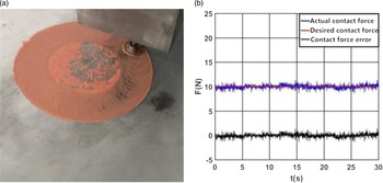
At the beginning of the experiment, the polishing agent cerium oxide and water are first applied to the area where the aluminum plate needed to be polished. Then, the motion program of the robot polishing the aluminum plate in text format generated by offline programming software is downloaded to the IMAC controller, and the robot is controlled to carry out the polishing operation according to the predetermined trajectory, as can be seen in Fig. 16(a). In this process, the adaptive impedance control algorithm is used to keep the 10 N polishing contact force unchanged. The actual contact force data at a certain period in the whole polishing process are finally extracted and drawn into a curve, as shown in Fig. 16(b).
The experiment of constant force polishing aluminum plate. (a) Field test drawing. (b) Polishing contact force curves.

As can be seen from Fig. 16(b), the actual contact force can be kept at 10 ± 1 N when the constant force polishing of the aluminum plate is carried out according to the predetermined trajectory, which could realize that the polishing contact force of the robot is relatively constant during the polishing of the aluminum plate. Therefore, the considerable adaptability and robustness of the adaptive impedance control algorithm are proved.
5. Conclusion
In this study, an adaptive impedance control method for the pneumatic servo-polishing system of an optical mirror processing robot is designed. In this method, the environmental stiffness and position are estimated online, so as to reduce steady-state error, and finally realize the tracking of polishing contact force. The simulations suggest that the adaptive impedance control method has a satisfactory control effect for different environmental stiffness and can achieve accurately tracking the polishing contact force. The constant force contact experiment of the optical mirror processing robot proves the high control accuracy of the adaptive impedance control method. The variable force tracking experiment verifies the fast force tracking response speed of the adaptive impedance control method. The variable environmental stiffness contact force experiment implies the adaptability of the polishing system to variable environmental stiffness. The experiment of constant force polishing the aluminum plate verifies the considerable adaptability and robustness of the adaptive impedance control method.
In this research, the gas is assumed to be an ideal gas and the gas flow process is regarded as isentropic and adiabatic. In other words, the mathematical model of the pneumatic servo-polishing control system established in this research has some limitations. Therefore, establishing a more perfect mathematical model to further improve the accuracy of the adaptive impedance control method is in future studies.
Acknowledgments
The authors give many thanks to Shandong Zhongheng Optoelectronic Technology Co., Ltd. and Henan Shenhuo Coal Industry & Electric Power Co., Ltd. for providing the experimental devices and the hybrid robot for verifying the effectiveness of the proposed approach.
Author contributions
Xujing Tian performed mathematical formula conception, experimental design, experimental implementation, and paper writing. Mengyao Lv and Ziyuan Jiang performed experimental design, experimental implementation, and experimental data processing. Jiazheng Sun, Hongzheng Zhao, Jinshuo Han, Wei Gu, and Gang Cheng performed experimental design and experimental implementation.
Financial support
This work was supported by the Priority Academic Program Development of Jiangsu Higher Education Institutions (PAPD) and the National Natural Science Foundation of China (Grant No. 52275039) and was gratefully acknowledged.
Competing interests
The authors declare no competing interests exist.
Ethical approval
Not applicable.