I. INTRODUCTION
Transition metal dichalcogenides such as molybdenum disulphide (MoS2) have properties that are beneficial in a wide range of tribological applications. MoS2 has a hexagonal crystal structure (D4h 6–P63/mmc) with a low friction coefficient resulting from the ease of its basal plane shearing. MoS2 is an attractive solid lubricant due to its low friction coefficient and good wear resistance in vacuum and inert environments. However, in humid environments, the MoS2 dangling bonds can react with moisture, inhibiting shearing of the MoS2 basal planes. Incorporating certain metals and oxides can improve the oxidation resistance of MoS2 while maintaining a relatively low friction coefficient in most environments. Reference Scharf and Prasad1–Reference Singh, Mutyala, Mohseni, Scharf, Evans and Doll3 MoS2-based solid lubricants are well suited for space applications as mechanical systems in satellites and launch vehicles that operate in environments where they are exposed to electromagnetic and particle radiations, large temperature (−80 °C to 250 °C) and pressure (vacuum to several atmospheres) variations, and variable environments (humid air to vacuum). Reference Roberts4
MoS2 films containing metals and oxides perform better tribologically than pure MoS2 when operating in both dry and humid environments. Reference Scharf, Kotula and Prasad2,Reference Stupp, Stupp, Plating and Francisco5,Reference Fox, Renevier, Teer, Hampshire and Rigato6 Metal and/or oxide doped MoS2 films have been studied to understand their microstructure and draw a correlation between the effect of doped element(s) and tribological properties. Ti–MoS2 and Sb2O3/Au–MoS2 films, in particular, have found their way into commercial applications. Reference Scharf and Prasad1,Reference Singh, Mutyala, Mohseni, Scharf, Evans and Doll3,Reference Fox, Renevier, Teer, Hampshire and Rigato6,Reference Singh, Mutyala, Evans and Doll7 Ti–MoS2 films deposited by magnetron sputtering were studied by Singh et al. using high resolution transmission electron microscopy (HRTEM) and they observed that their coating was completely amorphous and had featureless morphologies. Reference Singh, Mutyala, Mohseni, Scharf, Evans and Doll3 Furthermore, no second phase was observed even though the films contain about 16 at.% Ti. Renevier et al. studied Ti–MoS2 films using X-ray photoelectron spectroscopy (XPS), X-ray diffraction (XRD), and transmission electron microscopy (TEM), and hypothesized that Ti was either in interstitial positions in the a or c direction of the MoS2 lattice or it replaced Mo in the MoS2 matrix. Reference Renevier, Fox, Teer and Hampshire8 Hsu et al. used XRD and Raman spectroscopy to examine Ti-doped MoS2 nanotubes and postulated that the Ti atoms either reside in the 2H–MoS2 crystal structure or are intercalated between the MoS2 layers. Reference Hsu, Zhu, Yao, Firth, Clark, Kroto and Walton9
Scharf et al. and Singh et al. studied Au–Sb2O3–MoS2 films using TEM and observed Au-rich nanometer-sized precipitates in amorphous matrices of MoS2. Reference Scharf, Kotula and Prasad2,Reference Singh, Mutyala, Evans and Doll7 It was concluded that the MoS2 matrix was in a solid solution with Sb2O3 like Ti–MoS2. The mechanism behind this solubility is unclear but it was believed that the dopants reside either between the MoS2 basal planes or intercalated between the MoS2 basal planes.
Nevertheless, the inclusion of Ti and Sb2O3 is reported to increase hardness and density, suppress columnar grain morphology, increases load bearing capacity, and improve oxidation resistance in humid conditions as compared to undoped MoS2 films based on TEM, XRD, and XPS analysis. Reference Scharf and Prasad1–Reference Singh, Mutyala, Mohseni, Scharf, Evans and Doll3,Reference Stupp, Stupp, Plating and Francisco5 However, the exact arrangement of Ti and Sb2O3 dopant atoms in the MoS2 matrix is unknown/unexplored. Efforts to understand the arrangement of metal and/or oxide dopants in MoS2 films at atomic level to correlate the effect of Ti or Sb2O3 on the tribological properties of the MoS2 films are ongoing. Thus, 3D investigation with near atomic resolution is required to explain and understand the properties of metal doped MoS2 films.
Three-dimensional (3-D) atom probe tomography (APT) is a powerful microscopy technique with sub-nanometer scale chemical and spatial resolution. Reference Miller and Forbes10–Reference Kelly and Miller12 APT uses time of flight mass spectroscopy for chemical identification and generates 3D reconstructions imaging the distributions of individual chemical species. This technique has been used mainly to study thin metal films in semiconductors to investigate variations in their composition, structure, and their segregation in nanocrystalline materials, and to understand their precipitate morphology and evolution in alloy development. Reference Gault, Moody, Cairney and Ringer13,Reference Kelly, Larson, Thompson, Alvis, Bunton, Olson and Gorman14 APT has been rarely used on tribological coatings, authors are aware of only one publication where APT was performed on WC/aC:H nanocomposite films. Reference Scharf, Romanes, Mahdak, Hwang, Banerjee, Evans and Doll15 Thus, the aim of this study is to use APT in combination with TEM to study Ti–MoS2 and Au/Sb2O3–MoS2 films prepared by magnetron sputtering to determine the elemental distribution, dopant position in the MoS2 lattice, and composition of the MoS2 doped films.
II. METHODS
A. Thin film deposition
Ti–MoS2 and Au–Sb2O3–MoS2 films were deposited by magnetron sputtering onto AISI 52100 steel substrate coupons. The steel coupons were degreased in a solvent, ultrasonically cleaned in an alkaline detergent, rinsed in deionized water, and, finally, dried in hot air before mounting on fixtures in the deposition chamber. Ti–MoS2 films were deposited in a closed-field unbalanced magnetron sputtering system (CFUMS). A description of the closed-field unbalance magnetron sputtering system can be found in the literature. Reference Strondl16 Two MoS2 and two Ti targets were sputtered with an Ar (purity 99.9%) gas flow maintained at 50 sccm. The Ti and MoS2 targets were arranged alternatively. The substrate bias voltage was kept below 60 VDC to promote sulfur stoichiometry, and the Ti and MoS2 target powers were 190 and 600 W, respectively. To establish desirable adhesion between the films and the steel substrate, a ∼200 nm layer of Ti was utilized. The total thickness of the Ti–MoS2 film including the Ti adhesion layer, and gradient layer was about 1 µm.
Sb2O3/Au–MoS2 films were deposited in a vacuum deposition system equipped with both radio frequency (RF) and direct current (DC) magnetrons. The RF magnetron was used to sputter a composite target composed of 82% MoS2, 11% Sb2O3, and 7% Au, and the DC magnetron was used to sputter a 99.99% pure titanium (Ti) target. The Ti target was sputtered first to create a Ti adhesion layer between the steel substrate and the MoS2 composite top layer. A Ti adhesion layer of ∼100 nm and a gradient layer were deposited first, followed by a ∼800 nm top layer from the composite target. Ti and Sb2O3–Au–MoS2 target powers were kept at 80 and 120 W, respectively.
B. Transmission electron microscopy
Specimens for transmission electron microscopy (TEM) were prepared using FEI (Nova 200 Nanolab and Helios 650, FEI Company, Hillsboro, Oregon) dual beam-focused ion beam scanning electron microscopy. A platinum film was deposited on the lift-out sections before final ion milling. The FEI Tecnai G2 F20 S-Twin and FEI Tecnai F30 scanning transmission electron microscopes (FEI Company) were used for imaging the Ti–MoS2 and Sb2O3/Au–MoS2 samples, respectively.
C. FIB preparation for APT
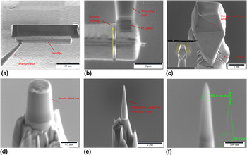
APT specimens were prepared using a FEI Helios Nanolab Focused ion beam (FIB; FEI Company) with an Omniprobe 200 micromanipulator to prepare site-specific specimens. Reference Thompson, Lawrence, Larson, Olson, Kelly and Gorman17,Reference Miller and Russell18 A thin protective layer of Ni was deposited by ion beam sputtering before preparing FIB specimens. Bar-shaped specimens were milled and lifted out and the sections were transferred onto standard atom probe silicon micro-posts. The micro-posts were then sharpened using annular milling patterns initially at 30 kV and then at 5 kV for the final sharpening to produce sharp needle samples with a 50–100 nm tip radius. Figure 1 shows the sequence of steps used for APT sample preparation.
Images (a)–(f) shows the sequence of steps used for APT sample preparation using a FIB-SEM lift out, mounting and tip sharpening technique.

D. APT parameters and methods
A Cameca LEAP 4000X Si (Cameca, Gennevilliers, France) was used to perform the APT analysis. The field evaporation was assisted by pulsing with a focused ultraviolet (355 nm) laser beam with pulse energies of 40–100 pJ per pulse, and a 250–500 kHz pulse repetition rate, at a base specimen temperature of 30 K. The atomic species were field evaporated from the surface of the tip with the aid of the pulsed laser. The evaporated atoms were collected and analyzed by means of a position sensitive time-of-flight mass spectrometry system. Reference Kelly and Miller12 Several specimens for both Ti–MoS2 and Au/Sb2O3 doped MoS2 were successfully analyzed.
The mass spectra obtained for the Ti–MoS2 film were somewhat complex because of the high percentage of multiple events (more than one ion is detected from a single laser pulse) for this sample. The multiple events can lead to reduced compositional accuracy. The analyses were conducted at lower temperature to cause a lower partial overlap of the peaks for the various molecular ions.
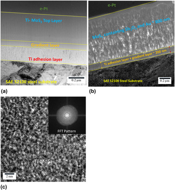
The APT specimens prepared from the Sb2O3/Au–MoS2 film tended to fracture during analysis due to the lower film density as shown in TEM image [Fig. 2(c)], even though less forceful APT experimental conditions (temperature 30 K, evaporation rate; 0.2–0.5% ion/pulse, repetition rate; 500 kHz, laser energy, 50 pJ) were chosen to minimize fracture. However, atom probe tips prepared near the gradient layer were successfully analyzed. Data analysis was performed using the IVAS 3.6.6 software.
TEM images revealing coating architecture of (a) Ti–MoS2 and (b) Sb2O3/Au–MoS2 (films are comprised of adhesion promoting Ti bond layers, compositionally graded layers transitioning between the Ti and the top layers, and a top layer of Ti–MoS2 and Sb2O3/Au–MoS2). (c) HRTEM image showing amorphous micro-structure with grain size less than 2 nm (inset diffraction pattern confirms the amorphous nature of film).

III. RESULTS AND DISCUSSION
Figures 2(a) and 2(c) shows cross-sectional TEM images of both Ti–MoS2 and Sb2O3/Au–MoS2 thin films. The total thickness of the Ti–MoS2 and Sb2O3/Au–MoS2 films is ∼1 µm. The architecture for both films consists of an adhesion promoting Ti bond layer on the steel substrate, a compositionally graded layer of Ti and MoS2, and a top layer of Ti–MoS2 or Sb2O3/Au–MoS2. Ti and Sb2O3 doping in the MoS2 films inhibits crystallinity, reduces film porosity, increases film density and results in better mechanical properties as compared to un-doped MoS2 films. Reference Scharf, Kotula and Prasad2,Reference Singh, Mutyala, Mohseni, Scharf, Evans and Doll3,Reference Stupp, Stupp, Plating and Francisco5,Reference Singh, Mutyala, Evans and Doll7 The TEM cross-sectional image shows that the Ti–MoS2 top layer is dense, and nonporous with featureless morphology. The HRTEM image [Fig. 2(b)] reveals that the Ti–MoS2 film is amorphous with grain size less than 2 nm. The diffraction pattern (inset) confirms the amorphous nature. The halo around the bright spot in the center from the transmitted electrons of the FFT pattern arises from the diffuse diffraction rings typical of amorphous materials. The TEM image of Sb2O3/Au–MoS2 exhibits a columnar morphology. The differences in film structure arise from the two deposition processes involved. The Ti–MoS2 films were deposited by a CFUMS system that produces dense coating morphologies due to high ion densities. The Sb2O3/Au–MoS2 films were deposited by a conventional sputtering method at a low substrate temperature (<100 °C) and substrate bias voltage (<60 VDC). The temperature and bias voltage was kept low since MoS2 films become increasingly sub-stoichiometric in sulfur with increasing substrate temperature and bias voltage. Reference Bichsel, Buffat and Levy19 In addition, higher substrate temperature can affect the Au particle size. Due to Ostwald’s ripening effect, the Au particles size grows with temperature which leads to Au agglomeration and may diffuse toward the surface and modify the tribological properties. Reference Singh, Mutyala, Evans and Doll7,Reference Scharf, Goeke, Kotula and Prasad20 Significant porosity is inherent in conventionally sputtered films deposited at low substrate temperatures and bias voltages.
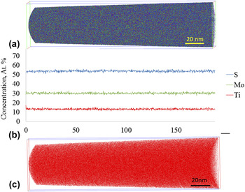
APT reconstruction of the Ti–MoS2 top layer is shown in Fig. 3(a). The reconstruction is obtained parallel to the film growth direction. S, Mo, and Ti atoms are shown as blue green and red dots, respectively. The reconstruction reveals that the Ti, Mo, and S atoms are wellmixed with no sign of clusters or precipitates. Detailed analysis by concentration frequency distribution and partial radial distribution functions confirm that no statistically significant deviations from a uniform elemental distribution can be detected. Due to lower lateral resolution in APT, 3-D crystallographic information depends on the structure of the material and the grain orientation of the sample. However, the present APT results do not indicate any compositionally heterogeneous spatial domains that may indicate crystalline features or grain boundaries indirectly. This is consistent with complementary electron diffraction results from TEM on these film samples that indicate an amorphous film structure. Specifically, the reconstruction indicates that the Ti atoms are uniformly distributed in the MoS2 matrix and no Ti-rich clusters or precipitates are present.
(a) Three-dimensional tomographic reconstruction of the Ti–MoS2 layer (S, Mo, and Ti are shown in blue, green, and red color, respectively). (b) Corresponding concentration profile along the long axis of the reconstruction, which corresponds to the growth direction of the film. (c) Tomographic reconstruction of Ti distribution in the Ti–MoS2 film (for interpretation of the references to the color, reader is referred to the colored version of the article).

The 1-D concentration profile was calculated by the bin size of 0.1 nm as a function of depth into the sample is shown in Fig. 3(b). Both the concentration profile and (as mentioned above) the distribution analysis by radial distribution functions and concentration frequency distribution analysis suggest that the elemental distribution of the constituents is completely random. The concentration of Mo, S, and Ti is constant with depth in the film and there are no local statistically significant variations in the concentrations of either Ti, Mo, or S along the investigated depth of ∼180 nm. A trace amount of nitrogen impurity is also present but is not shown here. The film contains about 30 at.% Mo, 20 at.% Ti, and 50 at.% S indicating that the films are sub-stoichiometric in sulfur, relative to an ideal MoS2 stoichiometry. This result corresponds well with earlier measurements conducted on the film. Reference Singh, Mutyala, Mohseni, Scharf, Evans and Doll3 The Ti concentration profile does not indicate a formation of layered structure even though during the deposition, the substrates were sequentially passed in front of MoS2 and Ti targets. Figure 3(c) shows the atomic distribution of Ti inside the MoS2 matrix. The uniform distribution of Ti demonstrates that there are no precipitates and the Ti is in solid solution with the MoS2.
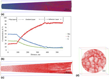
Figure 4(a) presents a 3D APT reconstruction of the top ∼100 nm Ti–MoS2 layer, ∼300 nm of the gradient layer, and ∼150 nm of the Ti adhesion layer. The gradient layer provides a strong bond between the top layer and the Ti layer, preventing coating delamination at the interface under high shear stresses and load conditions. The image shows about 20 nm of the top layer where the Ti concentration is less than 20 at.%. Below that layer, the Ti composition increases and reaches 90 at.% at the adhesion layer. Composition of Ti, Mo, and S is presented using red, green, and blue colors, respectively. 3D maps show that with an increase in Ti concentration, columnar grains begin to appear toward the end. No grains are discernible until the concentration of Ti reaches a certain limit. Figure 4(b) shows the 1-D concentration profile traversing from left to right of the top layer, the gradient layer and the adhesion layer. The first ∼100 nm of the film shows the concentration of top layer, followed by about 400 nm of gradient layer and ∼150 nm of adhesion layer. The atomic distribution of Ti in the analyzed stack comprising of three layers and corresponding cross-section from the bottom of the analyzed stack is shown in Figs. 4(c) and 4(d). The reconstruction of Ti atomic distribution shows the variation in Ti concentration in different layers. In the top 20 nm layer Ti atoms are uniformly distributed and at adhesion layer grains begin to appear. The cross-section illustrates the columnar morphology of the Ti adhesion layer. Furthermore, grain boundaries are clearly visible and concentration profiles (not shown here) of the specimen confirmed that the boundaries contain oxygen (∼4 at.%) and carbon (∼1 at.%) impurities. Mass spectra of the adhesion and gradient layer showed strong (TiO)2+ peaks at m/z of 31, 31.5, 32, 32.5, and 33. However, no such peaks are observed in the film indicating the absence of oxygen. This observation rules out substitutional oxygen impurity previously found in MoS2 films. Reference Lince, Hilton and Bommannavar21 The Titanium’s affinity to O and C is useful, well known, and purposefully used to attract those elements during the coating deposition process. Since Ti tends to form molecular ions, compound ions such as TiC, TiO, and TiO2 were observed in the mass spectrum.
APT 3D tomographic reconstruction and analysis of combined Ti–MoS2 top layer and gradient layer (a) 3-D atom map showing about 100 nm top Ti–MoS2 layer, about 400 nm gradient layer and about 100 nm adhesion layer (b) 1-dimensional concentration profile along the growth direction. (c) Distribution of Ti atoms along the investigated stack. (d) A slice through the 3D APT tomographic reconstruction in cross-section from the bottom of the analyzed stack in the Ti adhesion layer.

Ti can evaporate as a triply charged ion, Ti3+, a statistically significant distinction between 48Ti3+ and 16O+ can be made only if this peak is large enough to observe the other four isotopes of Ti (46Ti3+, 47Ti3+, 49Ti3+, 50Ti3+). Similarly, (48Ti16O)2+ overlaps with (16O2)+ at the 32 amu peak position. Observation suggests that small O contents tend to evaporate as molecular ions. A lower limit of the oxygen concentration with good fidelity can be estimated by considering only the peaks in the mass spectrum that can be identified in this way without ambiguity.
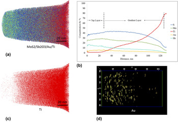
Figure 5(a) shows the 3D APT reconstruction of the 20 nm Sb2O3/Au–MoS2 top layer, the ∼100 nm gradient layer and the ∼5 nm Ti adhesion layer. S, Mo, Ti, and Sb are shown in blue, green, red, and cyan colors, respectively. The reconstruction from Fig. 5(a) indicates that the atoms are well mixed at a micro scale, but clustering is observed at nano or atomic scale. Figure 5(b) is a concentration profile for Ti, S, Au, and Sb along the depth direction of the film. The film contains about 5 at.% Au, 13 at.% Sb, 25 at.% Mo, and 38 at.% S and a trace amount of Ti in the top 20 nm layer. The Ti concentration begins to increase after 20 nm at about 80 at.%. After 100 nm at.%, the concentration of S, Mo, Sb, and Au decreases sharply with the Ti increase confirming the end of the gradient layer and beginning of adhesion layer. Fig. 5(c) shows the distribution of Ti atoms in the gradient layer.
(a) 3D atom by atom tomographic APT reconstruction of the Au/Sb2O3–MoS2 film showing the uniform distribution of atoms (S, Mo, Ti, and Sb are shown in blue, green, red, and cyan colors, respectively); (b) a concentration depth profile along the growth direction; (c) Ti concentration distribution in the investigated stack; (d) 2-D projection showing the Au clusters in the film after filtering with a cluster-identification algorithm.

The Au atoms are found to be clustered in small Au rich particles which were identified with a maximum separation algorithm in the data analysis software (IVAS). The Au particles may provide a load support for the reorientation of the MoS2 basal layers. The mixed layer is composed of Au nanoparticles surrounded by a MoS2 + Sb2O3 matrix.
The role of Sb2O3 in the MoS2 matrix may bear similarities to that of Ti as a dopant in Ti–MoS2 coatings. Specifically, the incorporation of both Ti and Sb2O3 in MoS2 films results in densification, increased hardness, decreased columnar morphology, and reduction in crystallite size. These attributes contribute to a reduction in friction and wear compared to undoped MoS2. An additional benefit of Sb2O3, like titanium, is that it may act as an oxygen getter to increase the coating lifetime in humid environments. Reference Scharf, Diercks, Gorman, Prasad and Dugger22,Reference Centers23 The distribution of these Au-rich particles inside the Sb2O3 and MoS2 matrix is shown in Fig. 5(d). Sb and O enrichments are detected, which are preferentially located at the surfaces of these small Au-rich clusters. The concentration profile Fig. 5(b) of the analyzed sample provides detailed and quantitative information about the overall elemental distribution in the top and gradient layers.
Owing to the tendency of the amorphous alloys to evaporate in an irregular pattern, the reconstruction is hampered by atomic density fluctuations. Because of the difference in the evaporation fields of different chemical environments, certain local magnification and trajectory overlap effects can occur, Reference Vurpillot, Bostel and Blavette24 which may result in artifacts. However, the artifacts do not significantly influence the compositional information of the sample. Reference Müller, Sologubenko, Gerstl and Spolenak25 In addition, the preferential evaporation of certain elements can also result in reconstruction artifacts.
TEM characterization of Ti–MoS2 and Sb2O3/Au–MoS2 films revealed different morphologies highlighting the effects of deposition methods. Ti–MoS2 film are dense and featureless whereas Sb2O3/Au–MoS2 films have columnar morphology. APT results showed that Ti and Sb2O3 dopants are seen uniformly distributed in the film and observed to promote the amorphous character. APT analysis suggests that the Ti atoms are doped in the 2H–MoS2 lattice and are not intercalated between the MoS2 layers. The view is supported by XRD studies conducted on Ti-doped MoS2 nanotubes and Ti–WS2 films. Reference Hsu, Zhu, Yao, Firth, Clark, Kroto and Walton9,Reference Scharf, Rajendran, Banerjee and Sequeda26 Based on these two studies and APT results it is determined that Ti is likely present in the c-axis of MoS2 or WS2 as an interstitial solid solution, or is replacing Mo in the MoS2 matrix.
IV. CONCLUSIONS
Ti–MoS2 and Sb2O3/Au–MoS2 films were deposited using magnetron sputtering. TEM revealed that the Ti–MoS2 film is dense, and has an amorphous structure while Sb2O3/Au–MoS2 has a lower density and an amorphous structure with columnar grains. APT analysis of the Ti–MoS2 film showed a homogeneous distribution of Ti in the MoS2 matrix and no precipitate regions of high Ti concentration or Ti clustering. Concentration profiles, statistical analysis, and radial distribution functions analysis confirmed a uniform composition throughout the analyzed top Ti–MoS2 layer. Analysis of the gradient layer showed the formation of columnar grains as the Ti concentration surpassed 80 at.%. These results support the view that in this film, the Ti atoms are incorporated within the MoS2 structure and are not intercalated between the MoS2 layers. Furthermore, incorporating at least 16 at.% of Ti is sufficient to remove any long-range crystallographic order of MoS2.
Sb2O3/Au–MoS2 films also exhibited both homogeneous elemental distribution of Sb2O3 throughout the MoS2 matrix and the presence of Au clusters. It is concluded from this work that Sb2O3 functions similarly to Ti and eliminates the crystallographic order of 2H–MoS2 while Au atoms form well-dispersed nanometer-sized precipitates.
It is the focus of a further study to determine the maximum Ti and Sb2O3 concentrations that can be incorporated into MoS2 films and still maintain crystallographic order, and if low concentrations of these elements form intercalated structures.
ACKNOWLEDGMENT
The Authors are thankful to The Timken Company for providing funding. The authors wish to thank Hamidreza Mohseni (now at Bosch) and Thomas Scharf at UNT Center for Advanced Research and Technology (CART) for the FIB/TEM analyses on Ti–MoS2 films. Authors would also like to thank Dieter Isheim and Sung II Baik for the useful discussions and assistance in atom probe tomography at NUCAPT Northwestern University.