



Introduction
A momentum is inherent in electromagnetic waves as they traverse through free space. This form of momentum includes spin angular and orbital angular (OAM). OAM is tied to the helical transverse phase configuration. The helical pattern is characterized by  $\exp(jl\phi)$, where l signifies the OAM mode order, and ϕ denotes the transverse azimuthal angle [Reference Yao and Padgett1–Reference Mohaghegh Mohammadi, Daldorff, Bergman, Karlsson, Thide, Forozesh, Carozzi and Isham3]. It offers extra freedom within the topological charge domain, enhancing the potential to strengthen communication capacity [Reference Wang, Yang, Fazal, Ahmed, Yan, Huang, Ren, Yue, Dolinar and Tur4–Reference Park, Wang, Brüns, Gun Kam and Schuster7]. While the initial experimental validation of OAM waves in the radio frequency realm was documented in 2007, incorporating them into practical applications has proven to be a difficult task, as acknowledged in [Reference Allen, Beijersbergen, Spreeuw and Woerdman8–Reference Tamburini, Mari, Sponselli, Thidé, Bianchini and Romanato10].
Several methods for producing vortex beams within microwave fields have been published, such as uniform circular arrays, patch antennas, and metasurfaces (MSs). A uniform circular arrays produce OAM beams, but element closeness complicates the feed network [Reference Jingcan, Song, Yao, Zheng, Gao and Huang11]. The patch antenna designed for OAM demonstrates high mode purity at higher orders, but the single-feed [Reference Weiwen, Zhang, Yang, Zhuo, Longfang and Huo Liu12] has low gain and limited bandwidth, while the multi-feed [Reference Huang, Xiuping, Qingwen, Zihang, Zhu, Akram and Jiang13] is complex. MSs, representing a specific type of metamaterial limited to two dimensions, have gained significant popularity as a preferred method for creating radio frequency OAM vortex beams [Reference Yang, Sun, Sha, Huang and Jun14–Reference Shi, Wang, Peng, Chen, Jianxing, Zhu, Zhang and Zhuo18]. Both reflective and transmissive MSs [Reference Wang, Pan, Yang, Shenheng, Maokun and Donglin19–Reference Qiu, Xiuping, Zihang, Zhao and Huang29] offer comparable advantages, such as streamlined design, cost-effectiveness, ease of fabrication, and operational simplicity. The utilization of transmissive MS can mitigate feed blockage effects in contrast to reflective MS.
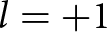
Recent publications showcase progress in  $ l =\pm 1$ OAM vortex beam generation in the Ka-band using four-substrate layers. One study used a variable size method for identical layers at 30 GHz, obtaining 33.3% OAM bandwidth despite a relatively high profile (0.8λ 0 = 8.0 mm) [Reference Ishfaq, Xiuping, Zihang, Zhao, Aziz, Qiu and Memon28].
Another approach used a rotation method with non-identical layers at 33.5 GHz, resulting in an achievement of 28.4% bandwidth and an overall thickness of 0.28λ 0 as reported in [Reference Qiu, Xiuping, Zihang, Zhao and Huang29]; however, this configuration faced limitations in OAM bandwidth. In [Reference Cai, Yan, Xiang-Jie, Yang and Fan26], utilizing variable sizing and rotation, a double conducting layer transmitarray generated an  $l=+1$ OAM beam at 18 GHz, showcasing an impressive 11.1% bandwidth and an overall thickness of 0.12λ 0, including vias. In [Reference Qin, Wan, Lihong, Zhang, Wei and Gao25], utilizing the dimension extension method with different elements at 18 GHz generated a single OAM beam via vias. Additionally, Ku-band OAM beams with a 7.4% bandwidth were generated using a refined feeding network that incorporated a phase delay line, as detailed in [Reference Qin, Gao, Cheng, Liu, Zhang and Wei24]. Furthermore, a single
 $l=+1$ OAM mode was generated at a specific frequency using three substrate layers and an overall thickness of 0.15λ 0, as described in [Reference Huan-Huan, Huang, Xiang-Jie, Hou and Shi23]. Achieving high mode purity in wideband OAM vortex beams free from vias, minimizing overall profile with low loss, and reducing complexity are crucial for versatile applications, including radar and wireless communication systems. Further research is needed to advance these capabilities.
This research aims to introduce a three-substrate layers transmitarray with an identical structure to generate a wideband vortex beam carrying OAM within the Ka-band. Our proposed symmetrical structure without vias significantly minimizes the overall profile while maintaining a transmission loss close to unity. A prototype is fabricated and evaluated to validate our proposed design. The proposed transmitarray holds considerable promise for practical applications involving OAM wave utilization.
Developing the design of a transmissive unit cell
Figure 1 illustrates the progression of our proposed element, from its initial configuration in step-1, through adjustments made in step-2, to the final proposed element presented in step-3. The proposed transmissive element has three substrate layers, each incorporating identical conductor layers on the upper and lower surfaces. F4B substrate is employed in the unit cell ( $\varepsilon _{r} = 2.65$ and
 $\tan \delta = 0.001$) with periodicity
 $P = 0.5\lambda _{0} = 5.0\ \mathrm{mm}$ at 30.0 GHz. The unit cell geometry parameters are given in Table 1.
Proposed transmitarray element geometry. (a) The progression of our proposed element. (b) Profile view. (c) Overhead view.

Proposed element geometry parameters (units: mm)

The performance of various step configurations was evaluated into finalize the proposed element. The step-1 was comprised of a square loop with a diagonal dipole. We introduced a square patch to enhance transmission by varying the size of the square patch. Then in step-2, we subtracted a fixed cross dipole ( $L = 1.5\ \mathrm{mm}$) from the square patch to address transmission loss and phase issues. However, as depicted in Figure 2(a) and (b), these outcomes did not fully resolve our transmission loss and phase concerns. Ultimately, increasing the size of the cross dipole relative to the square patch in step-3 proved effective by achieving close-to-unity transmission magnitude and linearly phase of more than 360∘. Figure 3 illustrates the polar diagram of the proposed element, showcasing the comparison between theoretical and simulated execution based on cascading S-parameters [Reference Abdelrahman, Elsherbeni and Yang30]. The theoretical outcome closely corresponds with the simulated result, demonstrating the potential to achieve a complete 360∘ transmission phase while upholding a 1-dB transmission loss.
The progressive response of the transmissive unit cell in both phase and magnitude. (a) Step-1. (b) Step-2. (c) Step-3 (proposed element).

The transmission amplitude and phase in a polar diagram, considering both theoretical and simulated scenarios.

Figure 4 illustrates the comparative responses of our proposed element when applied to either a single side or both sides of each substrate. Remarkably, the proposed element achieves near-unity magnitude and a 360∘ phase when printed on both sides of the substrate.
The comparison response of transmission magnitude and phase. (a) Single side of each substrate. (b) Both side of each substrate.

We utilized ANSYS HFSS software to assess the transmission properties, including magnitude and phase of the proposed element design by varying the sizes of N1. A detailed parametric analysis was conducted to determine optimal unit cell dimensions within the range of N1, changing from 2.36 to 4.61 mm, aiming for efficient performance. Figure 5 illustrates the outcome of the proposed element in relation to the magnitude and phase for different air gap (H1) and width (W) values. By optimizing the unit cell, we attained the most favorable transmission phase values and magnitudes at  $H1 = 0.5\ \,\mathrm{mm}$ and
 $W = 0.16\ \,\mathrm{mm}$.
The outcome of the transmissive element in relation to magnitude and phase. (a) H1. (b) W.

Analyzing the transmitarray unit cell across oblique incident angles is crucial for verifying its performance in transmission magnitude and phase, as shown in Figure 6. The results show stable responses up to 30∘, with minor amplitude deviations that do not affect performance. The phase phase dispersion calculated under standard incidence suffices to achieve OAM vortex beams without compensation for phase delay.
The outcome of the element in relation to phase and magnitude with incident angles at operating frequency.

Design of array for OAM
In Figure 7, the proposed transmitarray displays a square planar aperture with dimensions of  $100\times100\,\mathrm{mm}^{2}$, specifically designed to produce (
 $l = +1, +2, +3, +4 $) OAM modes. A horn feed is positioned at vector
 ${{\vec{d_{f}}}}$ to realize this setup. Determining each element’s phase shift
 $\psi_{m n}$ involves various factors to achieve the desired beam using the following equation
 \begin{equation}
\psi_{m n}=k_0 \times\left(\left|\vec{d}_{m n}-\vec{d}_f\right|-\vec{d}_{m n} \cdot \vec{u}\right)+l \times \tan ^{-1} \frac{Y_{m n}}{X_{m n}}
\end{equation}
 \begin{equation}
\begin{aligned}
& X_{m n}=x_{m n} \cos \theta \cos \varphi+y_{m n} \cos \theta \sin \varphi \\
& Y_{m n}=-x_{m n} \sin \varphi+y_{m n} \cos \varphi.
\end{aligned}
\end{equation}
These include  ${k_{0}}$ (wave number in free space),
 ${{\vec{d}_{m n}}}$ (element’s position in rows and columns),
 ${\hat{\mu}_{0}}$ (directional vector), and l (specific OAM mode numbers,
 $l = +1, +2, +3, +4 $). Additionally, (
 $X_{m n}$,
 $Y_{m n}$) specify the element’s location in the beam’s normal plane. The OAM transmitarray design involved a 30 GHz linear polarization horn antenna. We achieved optimal performance and reduced spillover losses by carefully selecting an f/D ratio, ultimately settling on 1 after optimization.
(a) Representation of OAM generation through the transmitarray. (b) Physical mask.

Simulated and measurement findings
The performance of the transmitarray in generating OAM vortex beams occurred through the utilization of the ANSYS HFSS simulation tool. In Figure 8, we simulate the electric field phase characteristics, illustrating a spiral pattern with four distinct OAM modes ( $l = 1, 2, 3, 4$) at a frequency of 30 GHz were noted on the
 $z = 300\ \mathrm{mm}$ plane. Similarly, in Figure 9, we depict the simulated amplitude distribution of these same four OAM modes. As the OAM mode number rises, the doughnut-shaped electric field’s radius sequentially expands, associated with a growing radiation pattern cone angle. Additionally, Figure 10 presents the mode purity of these four modes. While our simulations demonstrate high purity for higher-order OAM modes (Mode-2, Mode-3, Mode-4), experimental measurements focused on Mode-1 due to the significant increase in costs for higher-order modes.
Simulated phase characteristics of the E-field were noted on the  $z = 300\ \mathrm{mm}$ plane at operating frequency (a) +1 mode. (b) +2 mode. (c) +3 mode. (d) +4 mode.

Simulated magnitude characteristics of the E-field were noted on the  $z = 300\ \mathrm{mm}$ plane at operating frequency (a) +1 mode. (b) +2 mode. (c) +3 mode. (d) +4 mode.

Simulation results for the purity of OAM modes at operating frequency. (a) +1 mode. (b) +2 mode. (c) +3 mode. (d) +4 mode.

Additionally, we evaluated the consistency of the OAM wave at varying spans (ranging from 30λ 0, 50λ 0, 70λ 0, and 100λ 0 at 30 GHz) from the transmitarray origin. Figure 11 displays the assessment using a  $300\times 300\ \mathrm{mm}^{2}$ viewing surface.
Observations of simulated E-field attributes phase and magnitude at various planes for the  $l = +1$ mode.

It’s worth emphasizing the consistent generation of the unique doughnut-shaped magnitude distribution characteristic of OAM mode  $l = +1$ over these distances. This underscores the reliability of our transmitarray and confirms its aptness for extending OAM wave applications over extended distances effectively. The assessment of OAM mode purity involves utilizing a computational Fourier analysis applied to the phase distribution across the aperture following the definition from [Reference Yao, Franke-Arnold, Courtial, Barnett and Padgett31]
 \begin{equation}
A_{l_{n}}=\frac{1}{2 \pi} \int_{0}^{2 \pi} \Psi(\psi) e^{-J l_{n} \psi} d \psi
\end{equation}
 \begin{equation}
\text {Purity }=\frac{\left|A_{l_{n}}\right|}{\sum_{m=-\infty}^{+\infty}\left|A_{l_{m}}\right|}.
\end{equation}
Based on the simulation results, the proposed model exhibits significant achievement, obtaining an impressive OAM mode purity of 95% at operating frequency. Moreover, Figure 12, the OAM mode purity of  $l = +1$ consistently maintains levels above 86% across the frequency spectrum from 27.0 to 40.0 GHz. Furthermore, the specific value of θ for each mode is as follows:
 $-4.7^{\circ}$ at 27 GHz,
 $-4.5^{\circ}$ from 27.5 to 32.5 GHz, 4.6∘ from 33 to 36.5 GHz, and 4.7∘ from 37 to 40 GHz. That indicates a favorable mode purity bandwidth of 43.3%.
Simulation outcomes depicting the purity of +1 OAM modes across various frequencies.

Figure 13 provides an overview of the experimental setup and the proposed fabricated design model. The constructed TA possesses a total size of  $130\times 130\,\mathrm{mm}^{2}$, featuring individual elements that encompass an active square aperture measuring
 $100\times 100\,\mathrm{mm}^{2}$. A near-field scanning approach is utilized to assess the electric field properties of the fabricated design. The scanning plane encompasses a region measuring
 $200\times 200\,\mathrm{mm}^{2}$ and is sampled at
 $61 \times 61$ points. Figure 14 presents the functionality of the innovative design across a broad frequency spectrum, displaying simulated Figure 14(a) and measured Figure 14(b) near-field responses, including both phase and amplitude, throughout the frequency span ranging from 27 to 40 GHz.
The testing setup for the proposed prototype.

E-field properties including phase and amplitude were noted on the  $z = -200\ \mathrm{mm}$ plane at different frequencies. (a) Simulated. (b) Measured.

The obtained outcomes showcase a spiral phase characterized by a singular arm and a unique intensity profile akin to the shape of a doughnut. Across the frequency spectrum of 27–40 GHz, the transmitarray successfully produces  $l = +1$ OAM vortex mode. Figure 15 illustrates the standardized radiation configuration at the operating frequency, both simulated and measured, displaying precise cone-shaped beams in both the elevation and horizontal planes. Remarkably, these OAM beams show a central void of energy, which aligns with the successful generation of OAM mode +1. Moving to Figure 16, we present the measured data for the transmitarray gain and corresponding aperture efficiency. The experimental maximum gain achieved 21.7 dBi with 11.8% aperture efficiency. Additionally, the transmitarray demonstrates an OAM bandwidth of 43.3% over throughout the frequency span ranging from 27 to 40 GHz.
Measured and simulated normalized radiation patterns at the operating frequency, showcasing the E-plane in (a) and the H-plane in (b).

Measured gain and correlated aperture efficiency varying frequencies.

However, our proposed transmitarray achieves a good balance of identical conductor layers without relying on vias and broadband OAM beams producing.
Conclusion
In conclusion, the transmissive element introduced in our study has demonstrated its efficacy in generating a +1 OAM mode across a wide 27.0–40.0 GHz frequency range in the transmitarray system. Its symmetrical design ensures adaptability to dual-polarized applications. The transmitarray showcases outstanding performance metrics, achieving a maximum gain of 21.7 dBi with 11.8% aperture efficiency and a broadband OAM bandwidth of 43.3%. Consistently, across the wideband frequency range, our proposed transmitarray upholds a mode purity exceeding 86%. As a result, it emerges as a favorable option for wireless communication applications that leverage OAM. Its elegance lies in its simplicity and its adaptability to a wide spectrum of OAM vortex beams, making it a standout solution.
Data availability statement
The data that support the findings of this study are available from the corresponding author upon reasonable request.
Acknowledgements
This work was supported by the National Natural Science Foundation of China under Grant (62321001).
Competing interests
The authors affirm that they do not possess any identifiable financial conflicts of interest or personal connections that might have seemed to exert an influence on the research presented in this paper.

Muhammad Ishfaq received the B.S degree in electrical engineering, in 2009 and the M.S. degree in electrical engineering specialization in signal processing and wave propagation from the Linnaeus University, Vaxjo, Sweden, in 2013. He is currently pursuing the Ph.D. degree with the Beijing University of Posts and Telecommunications, China, in 2018. His current research interests include OAM antennas and transmitarray/reflectarray metasurface.

Xiuping Li (M’05-SM’07) received the B.S. degree from Shandong University in 1996, the Ph.D. degree from Beijing Institute of Technology in 2001. From 2001 to 2003, she joined in Positioning and Wireless Technology Center, Nanyang Technological University in Singapore, where she was a research fellow and involved in the research and development of RFID system. In 2003, she was a research professor in Yonsei University, Seoul, South Korea. Since 2004, she joined Beijing University of Posts and Telecommunications as associate professor and promoted to professor in 2009. She has been selected into the New Century Excellent Talents Support Plan in National Ministry of Education, the Beijing Science and Technology Nova Support Plan, in 2007 and 2008 respectively. She won the second prize of the Progress in Science and Technology of China Institute of Communications and the Excellent Achievements in Scientific Research of Colleges and Universities in 2015 and 2018, respectively. She is the author of 4 books, over 200 journal and conference papers. She is also awarded more than 20 PRC patents. Her current research interests include millimeter-wave antennas, THz antennas, RFID systems, and MMIC design.

Zihang Qi received the B.E. degree in electronic and information engineering from China Three Gorges University, Yichang, China, in 2013, and the Ph.D. degree in electronic science and technology from the Beijing University of Posts and Telecommunications, Beijing, China, in 2019. He is currently an associate research fellow with the Beijing University of Posts and Telecommunications. His current research interests include OAM antennas, millimeter-wave/THz antennas, and microwave filters.

Abdual Aziz (Member, IEEE) received the B.S. degree in electrical engineering from Bahauddin Zakariya University, Multan, Pakistan, in 2003 and the M.S. degree in telecommunication engineering from the University of Engineering and Technology, Peshawar, Pakistan, in 2008. He received the Ph.D. degree in electronic engineering from Tsinghua University, Beijing, China, in 2019. He has been an Associate Professor with the Islamia University of Bahawalpur since 2009. He has also experience of working in telecom industry from 2004 to 2009. He is also HEC approved supervisor and supervising several M.S. and Ph.D. scholars. His research interest includes transmissive and reflective metasurfaces, antennas, and applied electromagnetics. He also has several research publications in peer reviewed international conferences and journals.

Wenyu Zhao received a B.S. degree and Ph.D. degree from the Beijing University of Posts and Telecommunications, Beijing, China, in 2018 and 2023, respectively. He is currently a post-doctoral with the School of Electronic Engineering and the Beijing Key Laboratory of Work Safety Intelligent Monitoring at the Beijing University of Posts and Telecommunications. His current research interests include dual-polarized antennas, millimeter-wave antennas, and reflect array antennas.

Abdual Majeed received his Master of Philosophy in Electronics (Electromagnetic and Microwave Engineering) from Quaid-i-Azam University, Islamabad, Pakistan. He is currently pursuing a Ph.D. degree in the School of Electronics Engineering at Beijing University of Posts and Telecommunications, Beijing, China. His research interests include metasurfaces, metamaterial antennas, electromagnetic wave and propagation, RF/microwave engineering, wireless power transmission, microwave, millimeter wave system and devices, surface plasmon resonance, chiral, and bi-isotropic substrates.

Zahid Iqbal received the B.S degree in 2017 and the M.S. degree from Beijing University of Posts and Telecommunications, Beijing, China in 2020, where he is currently pursuing the Ph.D. degree with the School of Electronic Engineering and the Beijing Laboratory of Work Safety Intelligent Monitoring. His current research interests include reconfigurable antennas, wideband antennas, and reflectarray antennas.



