



1. Introduction
Spray combustion of liquid fuels accounts for a significant portion of the energy-harvesting mechanisms used in various fields. It consists of a fuel jet that atomizes into tiny droplets, vaporizes and then burns as a droplet cluster with highly nonlinear interactions. Droplet scale phenomena such as vaporization, secondary atomization, droplet flame dynamics and their interaction with the local flow, all play a significant role in the overall performance of such spray systems. As a result, many researchers have focused on droplet combustion studies that enabled them to delve into the underlying transient physical and chemical phenomena that occur in a burning droplet (Faeth Reference Faeth and Chigier1979; Law Reference Law1982; Sirignano Reference Sirignano1983). Depending on the environment, a burning droplet exhibits a wide range of droplet-level flame characteristics, such as micro-explosions, secondary atomization and forward extinction, leading to wake flame structures that exhibit shedding, extinction, transitions and so on.
Although droplet combustion studies cannot be directly extended to practical results for reacting spray systems, isolated single droplet combustion provides us insights into certain phenomena (extinction, stabilization, pollutant formation etc.) under well-controlled conditions, which allows us to make predictions for more complex situations (Williams Reference Williams1973). For a burning droplet in a quiescent environment, fuel vaporizes at the surface, and a diffusion flame is established at the stoichiometric plane enveloping the droplet (enveloped flame). Researchers performed contactless droplet experiments both under microgravity and gravitational environments and showed the dependence of evaporation characteristics on the droplet diameter (d) (Hara & Kumagai Reference Hara and Kumagai1994; Huang & Chen Reference Huang and Chen1994). A  ${d^2}$-law has been established as a droplet regression model during droplet combustion.
The flame characteristics of moving droplets investigated in the current work can give insights into the local extinction/blowout events which occur in spray combustion applications. In practical applications, a relative motion between the droplet and the surrounding gases exists, which might alter the vaporization characteristics and flame configuration. The flame gets slightly distorted at low relative velocities; however, at high relative velocities, the flame can blow-off or transition into the droplet wake, which occurs due to extinction at the forward stagnation point (Raghavan, Pope & Gogos Reference Raghavan, Pope and Gogos2006).
Researchers studied the combustion characteristics of burning fuel droplets in hot oxidant convective flow and showed that convection (natural/forced) has a strong influence on the fuel-burning rates (Fendell, Sprankle & Dodson Reference Fendell, Sprankle and Dodson1966; Law & Williams Reference Law and Williams1972; Balakrishnan, Sundararajan & Natarajan Reference Balakrishnan, Sundararajan and Natarajan2001). Wu, Sirignano & Williams (Reference Wu, Sirignano and Williams2011) numerically investigated the transient burning of an n-octane fuel droplet in hot gas streams. Results show that the flame stabilizes in the droplet wake when ignited in a flow at the Reynolds number, Re ∼ (45 and 67), whereas an enveloped flame was observed at Re ∼ 11 (lower Reynolds number). Likewise, Thirumalaikumaran, Vadlamudi & Basu (Reference Thirumalaikumaran, Vadlamudi and Basu2022) and Pandey et al. (Reference Pandey, Basu, Krishan and Vadlamudi2021) showed that local flow-field variations alter the droplet flame behaviour. The envelope-to-wake flame transition was observed when the burning droplet was incident with vortical structures. Miglani, Basu & Kumar (Reference Miglani, Basu and Kumar2014) and Basu & Miglani (Reference Basu and Miglani2016) showed that preferential acoustic perturbation (80–120 Hz) of the droplet flame leads to intermittent wake transition of the flame, which results in suppression of internal boiling in ethanol–water droplets due to low heat input to the droplet. The aforementioned studies showed the effect on the flame characteristics in the case of external flow imposed over a droplet flame. Similar results were observed in the case of moving droplet studies performed to explore the combustion characteristics in freely falling burning droplets. Drop tower studies were conducted by Makino & Fukada (Reference Makino and Fukada2005), Guerieri, DeLisio & Zachariah (Reference Guerieri, DeLisio and Zachariah2017) and Guerieri et al. (Reference Guerieri, DeCarlo, Eichhorn, Connell, Yetter, Tang, Hicks, Bowen and Zachariah2015) in an oxygen-rich environment, where the droplet flame remained fully enveloped during its fall. Li & Zhou (Reference Li and Zhou2013) numerically investigated the gas flow and flame structures surrounding a combusting ethanol droplet and showed that flame exhibited three combustion regimes – fully enveloped, partially enveloped and wake flames.
Researchers like Huang (Reference Huang2018) and Xiong & Huang (Reference Xiong and Huang2021) investigated freely falling combusting molten polyethylene droplets. The droplet flame is observed to stabilize in the far wake, which exhibited shedding due to the generated von Kármán street (BVK). The shedding and extinction criteria were studied, and the far-wake flame was shown to be similar to an edge-stabilized laminar lifted flame. The condition for such stabilization was investigated by Chung (Reference Chung2007), wherein the stabilization criteria and different edge-stabilized flame structures were discussed. The lifted flame is an edge-stabilized flame typically having a triple-flame or tribrachial structure with two premixed flame fronts i.e. fuel-rich, fuel-lean branches and a diffusion flame front arising from the stoichiometric location (Phillips Reference Phillips1965; Liñán Reference Liñán, Buckmaster, Jackson and Kumar1994). In the case of non-premixed flames, the edge-stabilized flame fronts can be either attached to the burner rim or stabilized as a lifted flame. Ghosal & Vervisch (Reference Ghosal and Vervisch2000) showed that the triple flame modifies the upstream flow resulting in the local fluid velocity closer to the laminar flame speed at the stabilization point. Researchers (Kim, Won & Chung Reference Kim, Won and Chung2007; Jeon & Kim Reference Jeon and Kim2017) showed that the flame height reduces and width increases with increasing flow rates for non-premixed laminar far-field lifted flames with annular co-flow jets. Partially premixed near-field lifted laminar flames showed a linear variation of flame height with the jet flow velocity, unlike the nonlinear trends of far-field lifted flames (Qin, Puri & Aggarwal Reference Qin, Puri and Aggarwal2002; Van et al. Reference Van, Jung, Yoo, Oh, Lee, Cha, Park and Chung2019). Lu & Matalon (Reference Lu and Matalon2019, Reference Lu and Matalon2020) investigated the near-wake edge-flame stabilization mechanism, orientation and position of the edge flame in a mixing layer.
Another type of flame stabilization was observed by Pandey et al. in a freely falling fuel droplet, where the flame is stabilized in the near wake at the rear recirculation zone (Pandey et al. Reference Pandey, Basu, Vadlamudi, Potnis and Chattopadhyay2020), similar to a bluff-body-stabilized flame. The parallels can be drawn with the flame established over a flame holder (acting as a bluff body) with a central fuel jet and an annular airflow around it. The flow field behind a bluff body consists of two vortical structures inside the recirculation zone – an outer vortex near the air jet and an inner vortex between the outer vortex and the fuel jet (Masri & Bilger Reference Masri and Bilger1985; Roquemore et al. Reference Roquemore, Tankin, Chiu and Lottes1986; Chin & Tankin Reference Chin and Tankin1991; Dally et al. Reference Dally, Masri, Barlow and Fiechtner1998; Vance et al. Reference Vance, Shoshyn, de Goey and van Oijen2022). The recirculation zone is responsible for preheating the mixture, and its strength affects the heat capacity, flame stability and stabilization location. Balasubramaniyan (Reference Balasubramaniyan2021) showed that the bluff-body flames were observed to occur in three regimes – steady, varicose and sinuous depending on the Reynolds number (Re) and equivalence ratio. A simplified theoretical model was also proposed to estimate the temperature inside the recirculation zone, which was found to reduce with increasing flow rates and to reach a critical value at blowoff (Kundu, Banerjee & Bhaduri Reference Kundu, Banerjee and Bhaduri1977). Researchers like Shanbhogue et al., Tuttle et al. and Kariuki et al. studied the blowoff characteristics of bluff-body-stabilized flames and identified the mechanism of extinction along the flame sheet, followed by blowoff (Shanbhogue, Husain & Lieuwen Reference Shanbhogue, Husain and Lieuwen2009; Tuttle et al. Reference Tuttle, Chaudhuri, Kostka, Kopp-Vaughan, Jensen, Cetegen and Renfro2012, Reference Tuttle, Chaudhuri, Kopp-Vaughan, Jensen, Cetegen, Renfro and Cohen2013; Kariuki et al. Reference Kariuki, Dowlut, Balachandran and Mastorakos2016).
Even though the above literature has addressed the different flame stabilization mechanisms like edge-stabilized flames or bluff-body-stabilized flames, they were not specifically directed towards the droplet-level flame dynamics, such as droplet wake flame shape, stabilization criteria, the effect of the flame on the wake flow field or the flame transition criteria. Some of these were addressed in the drop tower experiments conducted by Chen & Lin (Reference Chen and Lin2012), Pandey et al. (Reference Pandey, Basu, Vadlamudi, Potnis and Chattopadhyay2020), Vadlamudi, Thirumalaikumaran & Basu (Reference Vadlamudi, Thirumalaikumaran and Basu2021) and other researchers, wherein the enveloped and wake flame dynamics of freely falling burning fuel droplets was studied.
Chen & Lin (Reference Chen and Lin2012) conducted experiments on the combustion of a small, monodispersed droplet train (Re < 10) and studied the effects of the droplet spacing. Due to the upside-down configuration of the flat flame used for ignition, an oxygen-rich, weak convective environment (downwards) was created, initially resulting in a reverse wake flame. As the droplet accelerated, the flame started to envelop the droplets into a spherical flame (see figure 1b) and transitioned to a wake flame before extinction. Pandey et al. (Reference Pandey, Basu, Vadlamudi, Potnis and Chattopadhyay2020) investigated the dynamics of freely falling fuel droplets in a drop tower facility, where the falling droplet was ignited using a pilot flame, and the near-wake flame dynamics was studied. A fully enveloped buoyant diffusion flame was formed in the initial phase, which transitioned into a wake flame due to forward extinction. The wake flame is reported to be bluff-body stabilized in the droplet wake (see figure 1b), and the round jet analogy (Schlichting Reference Schlichting1933; Tyler Landfried, Jana & Kimber. Reference Tyler Landfried, Jana and Kimber2015) was used for theoretical modelling. The suppression of the BVK instabilities at high Re was observed due to the high temperatures generated by the flame in the wake region.
(a) The schematic of the experimental set-up has a syringe pump and burner at the top for droplet generation, ignition and a co-flow arrangement with a central hollow tube to allow the droplet to fall through. High-speed cameras are mounted at appropriate vertical locations to observe the droplet flame dynamics.(b) The different flame configurations observed in the literature (Pandey et al., Vadlamudi et al., Huang, Xiong & Huang and Chen & Lin).

Vadlamudi et al. (Reference Vadlamudi, Thirumalaikumaran and Basu2021) used a unique ignition mechanism wherein the fuel droplet was ignited in pendant mode and then released to fall freely under gravity. As the droplet accelerated from rest, the flame transitioned from the enveloped to the wake configuration, and the flame was stabilized in the far wake with a tribrachial structure (see figure 1b). For the droplet wake flame (without a yellow tip), the flame height was found to decrease with increasing velocity, similar to the results shown by Kim et al. (Reference Kim, Won and Chung2007) for far-field lifted flames. However, if the upstream velocities were estimated with respect to the flame, accounting for the velocity of the flame's descent, flame height variation followed a similar trend as an attached flame or a near-field lifted flame. At higher Reynolds numbers, the induced von Kármán vortex shedding interacts with the wake flame leading to flame shedding or stretching. Similar observations were shown by Huang (Reference Huang2018) and Xiong & Huang (Reference Xiong and Huang2021), where a far-wake-stabilized droplet flame exhibited shedding and extinction due to the onset of BVK instability (see figure 1b).
The experiments by Huang, Vadlamudi et al. and Xiong & Huang were limited to the droplet flame dynamics only in the far wake, whereas the experiments by Pandey et al. dealt only with near-wake flame configurations (for Re > 30). However, the near-field wake flame dynamics in the lower velocity range (Re < 20) could not be investigated due to experimental limitations. In the case of Chen & Lin (Reference Chen and Lin2012), the experiments were primarily conducted to study the effect of droplet spacing, but the wake flame dynamics was not studied. Thus, the current study attempts to extend the previously established literature on the flame dynamics in combusting moving droplets by researchers like Pandey et al., Vadlamudi et al., Huang, Xiong & Huang and Chen & Lin.
The focus of the present study is to conduct a comprehensive study on the flame stabilization mechanisms at different Reynolds numbers and investigate the flame transition phenomena between enveloped, partially enveloped and near-wake flame configurations in a wide range of Reynolds numbers ( $0 < Re < 100$). The current study investigates the flame dynamics of freely falling burning dodecane droplets subjected to an air co-flow (downwards) opposing the buoyancy-driven flow. As the freely falling droplet encounters externally imposed annular co-flow, there is a transition of relative velocity around the droplet, and high co-flow velocities can even result in a reversal in the direction of local flow velocity. Because of this, unlike our previous studies, wherein a specific stable flame existed throughout the observation period, multiple flame regimes ranging from recirculation zone-stabilized wake flames to edge-stabilized flames, in both upright and reversed configurations, were noted, in addition to the enveloped flame structures around the droplet. The near-wake edge-stabilized flame was unique and was not explored in our previous works (Pandey et al. Reference Pandey, Basu, Vadlamudi, Potnis and Chattopadhyay2020; Vadlamudi et al. Reference Vadlamudi, Thirumalaikumaran and Basu2021). However, parallels could be drawn from the lifted flame configuration observed by Vadlamudi et al. (Reference Vadlamudi, Thirumalaikumaran and Basu2021) as, in both cases, the flame was stabilized locally by the same mechanism. A simplistic analysis for flame stabilization in the observed flame configurations is presented. The flame dynamics and the transitions noted are explained using classical theories, as well as the results obtained from our previous drop tower studies.
The primary objective of the current study is to comprehensively study the different flame structures, flame shape evolution and flame transitions under different Reynolds numbers imposed by the external flow. Such a study on the droplet wake flame can provide better insights into the flame dynamics, flame extinction criteria and local flame stability near the blow-out conditions in spray combustors, as shown by Chiu (Reference Chiu2000). Although the results of isolated droplet combustion studies, such as the current one, cannot be directly utilized in the actual spray combustors due to the effect of the droplet cloud formation that alters the global equivalence ratio and thus the flame dynamics (Reveillon & Vervisch Reference Reveillon and Vervisch2005), the results from such studies can be further extended to the dual and multi-droplet combustion studies, which can give insights into the flame dynamics in actual combustors.
The current study also focuses on observing the flame response when a burning droplet encounters a sharp local velocity fluctuation (achieved by imposing a co-flow around the burning droplet). However, the time scale associated with the droplet flame response and the velocity gradients imposed by the co-flow might not always reflect the corresponding scales in practical spray combustors, but might still provide insightful trends applicable to real world systems. Nevertheless, the current study also finds relevance in flame-spread control applications involving combustible polymeric droplet flames (melted insulation materials), which can encounter sudden gusts of winds during a fire hazard. Extinguishing such flames is a primary concern for fire control applications, and the present work, similar to the works of Huang and Xiong & Huang (wherein they investigated the flame spread and extinction in dripping polymeric melted droplets), contributes to the literature of such scenarios.
2. Experimental methodology
A vertical drop tower arrangement has been used to study the combustion dynamics of a freely falling burning droplet. Dodecane fuel droplets (d ∼ 2.9 ± 0.1 mm) have been generated using a syringe pump arrangement and are released to fall freely under gravity from the top of the drop tower (see figure 1a). The falling droplets pass through a butane pilot flame for primary ignition. Once ignited, the droplet is allowed to pass through the centre of the co-flow arrangement, present at 15 cm below the release point. The co-flow arrangement consists of an annular portion with radial inlets and an axial outlet on one side. The inlets are connected to a high-pressure line, and the flow is allowed to pass through a flow-straightening honeycomb before exiting the outlet. A central tube of 1.5 cm diameter is used to separate the central portion and annular co-flow portion. The freely falling droplet, after ignition, passes through this central tube and encounters the annular co-flow as it exits the tube (say z = 0). The central tube diameter is designed to avoid the extinction or quenching of the droplet flame.
The vertical section below the co-flow set-up is divided into different ROIs (regions of interest), each of size 6 × 6 cm2. The flame intensity imaging (at 2800 f.p.s., 1024 × 1024 resolution 10 μs exposure) and droplet shadowgraphy (at 5000 f.p.s., 1024 × 1024 resolution) have been recorded as the droplet passes through each of the ROIs. A Phantom Miro coupled with a Nikon Rayfact PF10445MF-UV lens has been used for flame intensity measurements. A Photron SA5 HSS high-speed camera (coupled with a combination of 100 mm Tokina macro lens and 36 mm extension tube) is used with a Veritas strobe light as a backlight for the shadowgraphy measurements. About 13 experimental runs have been conducted for each ROI located between 30 and 60 cm below the droplet release point. The droplet size is maintained constant for all the experiments, and it is found to remain unchanged in all the ROIs (since the flame is in the wake configuration during most of the flight time). The inlet flow rate for the co-flow is controlled using a pressure regulator, which alters the velocity of the co-flow (measured using an anemometer). The droplet flame responds to co-flow as it exits the central tube. The flame structure and flame shape evolution are studied using flame imaging at different ROIs for different co-flow velocities.
2.1. Image processing and data analysis of droplet shape
The droplet shadowgraph images were converted to binary using Otsu's thresholding technique for edge detection to isolate the boundary of the droplet in ImageJ software. Since the contrast between foreground and background is very high, the accuracy of the droplet edge detection is high, with an uncertainty of ±3.44 %. The binary format is utilized to extract the instantaneous droplet area and shape descriptors (aspect ratio and centroid). The droplet diameter (d) is evaluated by equating the instantaneous droplet area to that of a circle, i.e.  $A_d={\rm \pi} d^2/4$. The initial droplet diameter is maintained to be 2.9 ± 0.1 mm in all the experiments.
2.2. Flame imaging
High-speed flame imaging enables quantitative measurement of the flame location, shape and flame luminosity. The flame images have been thresholded using the Otsu thresholding technique (in built in ImageJ). Otsu's thresholding algorithm returns a single intensity threshold cutoff (If) that separates all the pixels in an image into two classes, foreground and background. This threshold cutoff (If) is determined by minimizing intra-class intensity variance or equivalently maximizing the inter-class variance by Otsu's algorithm. The flame boundary is isolated based on a cutoff intensity (If). The pixels (i,j) having intensity ≥ If are assigned a binary value of 1, and those with intensity < If are allocated 0. The resultant binary area comprising pixels having a value of 1 is used to calculate the instantaneous line-of-sight flame area (Af). The intensities of all the pixels in the actual raw image corresponding to value 1 in this line-of-sight flame image are used to evaluate the flame intensity or luminosity at each frame. The net flame intensity over the instantaneous flame area (Af) measured from the line-of-sight flame imaging is used to explain the variation of flame luminosity. These line-of-sight flame images were used to measure the instantaneous flame height, which is used in the analysis. However, these flame images were not obtained using OH* chemiluminescence due to experimental limitations of high-speed flame imaging of a low-intensity wake flame. This has been clarified during our previous studies using a pendant droplet wake flame to show that the flame front contour obtained is reasonably similar to that which is obtained using the OH* chemiluminescence for the type of wake flame under investigation. Further details are given in the supplementary material (see supplementary figure S1 available at https://doi.org/10.1017/jfm.2023.949).
The raw flame images used have an uncertainty of ±0.035 mm (based on the pixel resolution), which accounts to ±6 % deviation in the measurement of flame height, and the flame dimensions have been evaluated using 12 experimental runs for figure 3(b) (data extracted from our previous work; Vadlamudi et al. Reference Vadlamudi, Thirumalaikumaran and Basu2021). The uncertainty of flame height measurement is ±0.017 mm (±8 %) evaluated using 15 experimental runs corresponding to figure 6(c) (data extracted from our previous work; Pandey et al. Reference Pandey, Basu, Vadlamudi, Potnis and Chattopadhyay2020). The uncertainty of flame height measurement in our current experiments is ±0.073 mm (±7 %).
3. Results and discussion
3.1. Global observations
The falling fuel droplet is ignited using a pilot flame and is allowed to pass through the central tube of the co-flow set-up. After the droplet is released and ignited, a fully enveloped buoyant flame is established, which transitions into a wake flame beyond Re > 5 due to local extinction at the forward stagnation point. Forward extinction occurs when the local flame strain rate exceeds a critical value. As the droplet accelerates further, natural convection (responsible for transporting fuel to the flame front) becomes less dominant, reducing the size of the sooty yellow flame tip for 5 < Re < 10 (Pandey et al. Reference Pandey, Basu, Vadlamudi, Potnis and Chattopadhyay2020). Consequently, as Re increases further, the wake flame exhibits an edge-stabilized structure at the leading edge (Vadlamudi et al. Reference Vadlamudi, Thirumalaikumaran and Basu2021). Subsequently, the wake flame tip opens into an expanding jet-like open-brush-shaped structure, which is stabilized near the rear stagnation point. In current experiments, when the burning droplet exits the central tube ( $z = 0$), it attains a velocity close to 2.47 m s−1 (
 $Re \sim 110$), and the wake flame is observed to closely follow the droplet in the near wake. The open-brush wake flame is similar to a bluff-body-stabilized flame observed by Pandey et al. (Reference Pandey, Basu, Vadlamudi, Potnis and Chattopadhyay2020). The stand-off distances of the wake flame are of the same order of magnitude as the droplet diameter (d). As the droplet passes through the central tube exit, the wake flame begins to encounter the effects of the surrounding co-flow.
The experiments were performed with different co-flow velocities ( ${v_{o,i}}$), which yields a different flame dynamics as the fuel droplet accelerates due to gravity. The wake flame evolution of a falling droplet, as reported in the previous studies (Pandey et al. Reference Pandey, Basu, Vadlamudi, Potnis and Chattopadhyay2020; Vadlamudi et al. Reference Vadlamudi, Thirumalaikumaran and Basu2021), is altered in the current experiment due to the presence of the co-flow. After the droplet exits the central tube (
 $z = 0$) at
 $t = 0$, the vertical length (z) required for the droplet to perceive the co-flow velocity is 6 mm (
 ${\ll} 30\ \textrm{cm}$, drop tower height) and hence is neglected in the calculations. The data show an initial non-responsive period where the droplet flame does not respond to the imposed co-flow, and this corresponds to the aforementioned vertical distance of 6 mm. The different flame structures are identified qualitatively and are categorized in figure 2 as bluff-body stabilized, edge stabilized and enveloped flame. Figure 2 shows the time-series images of the wake flame for different co-flow velocities (
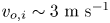
 ${v_{o,i}}\sim 2.2, 3,4\ \textrm{m}\ {\textrm{s}^{ - 1}}$). The flow velocities can be normalized with the laminar flame speed (
 $S_L^o$) and are represented hereafter as
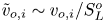 ${\tilde{v}_{o,i}}\sim {v_{o,i}}/S_L^o$. At the co-flow exit, i.e.
 $z = 0$, the co-flow velocity is lower than the initial droplet velocity,
 ${u_{o,i}}\sim 2.47\ \textrm{m}\ {\textrm{s}^{ - 1}}$ (
 ${\tilde{u}_{o,i}}\sim 3.9$), for the case when
 ${v_{o,i}}\sim 2.2\ \textrm{m}\ {\textrm{s}^{ - 1}}$ (
 ${\tilde{v}_{o,i}}\sim 3.5$). Hence, the absolute relative flow velocity of the surrounding flow with respect to the droplet is upwards, locally. However, in the case of
 ${v_{o,i}}\sim 3~\textrm{m}\ {\textrm{s}^{ - 1}}({\tilde{v}_{o,i}}\sim 4.8)\ \textrm{and}~4\ \textrm{m}\ {\textrm{s}^{ - 1}}({\tilde{v}_{o,i}}\sim 6.3)$, the co-flow velocity exceeds the initial droplet velocity (
 ${u_{o,i}}$), causing the absolute relative velocity to be directed downwards with respect to the droplet.
Time series of the flame imaging of a freely falling droplet interacting with a co-flow of velocity(a)  ${v_{o,i}}\sim 2.2\ \textrm{m}\ {\textrm{s}^{ - 1}}$ (
 ${\tilde{v}_{o,i}}\sim 3.5$), (b)
 ${v_{o,i}}\sim 3\ \textrm{m}\ {\textrm{s}^{ - 1}}$ (
 ${\tilde{v}_{o,i}}\sim 4.8$), (c)
 ${v_{o,i}}\sim 4\ \textrm{m}\ {\textrm{s}^{ - 1}}$ (
 ${\tilde{v}_{o,i}}\sim 6.3$). A colour bar is given on the right side for the corresponding flame luminosity shown in the flame images. The different flame shapes are indicated corresponding to the flame images.
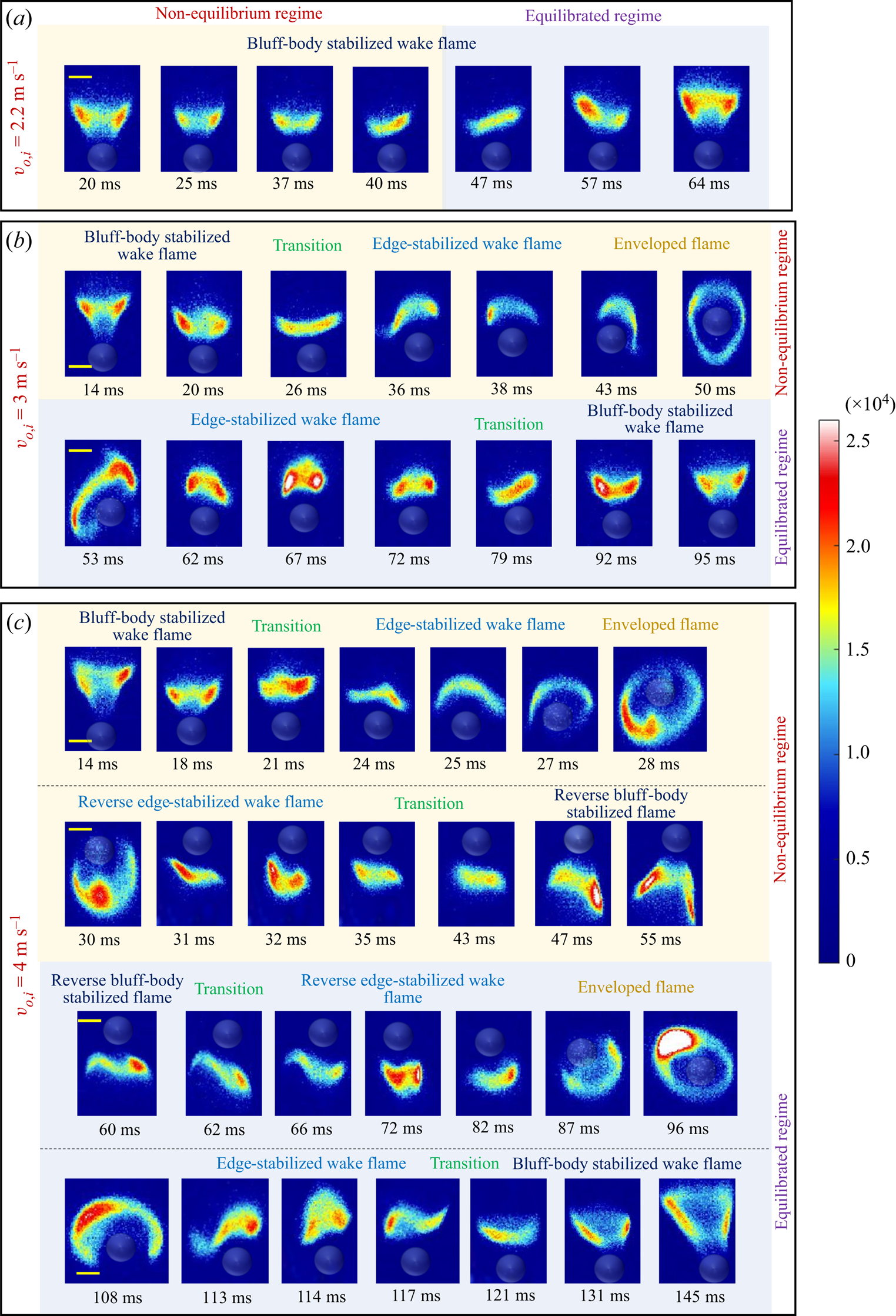
For the case corresponding to  ${v_{o,i}}\sim 2.2\ \textrm{m}\ {\textrm{s}^{ - 1}}$, see movie 1, the wake flame is observed to have an open-brush shape, similar to the observation of Pandey et al. (Reference Pandey, Basu, Vadlamudi, Potnis and Chattopadhyay2020). The wake flame height is observed to reduce as the droplet accelerates (
 ${u_o}$ increases) and the flame flattens. However, as shown in figure 2(a), after 40 ms, the flame height is observed to increase. On the other hand, for
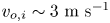 ${v_{o,i}}\sim 3\ \textrm{m}\ {\textrm{s}^{ - 1}}$ (see movie 2), both the wake flame shape as well as its structure vary as the droplet falls (see figure 2b). The initially present open-brush-shaped wake flame is observed to flatten, beyond which the flame structure is observed to dynamically go through intermediate states to transition into an edge-stabilized flame (branched-edge flame), similar to the structure reported by Vadlamudi et al. (Reference Vadlamudi, Thirumalaikumaran and Basu2021). The flame height of this edge-stabilized wake flame reduces temporally as the droplet falls until
 ${\sim} 43\ \textrm{ms}$, after which the wake flame starts to envelop the droplet, forming a spherical flame. At this point, there is a balance between natural convection and downward relative flow (Chen & Lin Reference Chen and Lin2012). Subsequently, the enveloped flame undergoes forward extinction and transitions into the wake configuration (
 ${\sim} 60\ \textrm{ms}$), regaining its edge-stabilized flame structure, whose height increases with time. Thereafter, the flame gradually transitions into an open-brush shape (around
 ${\sim} 75\ \textrm{ms}$) similar to the wake flame observed by Pandey et al. (Reference Pandey, Basu, Vadlamudi, Potnis and Chattopadhyay2020), wherein the flame height increases with time. It is to be noted that the transition between the edge-stabilized and open-brush-shaped wake flame is a gradual process, where the wake flame goes through intermediate stages before fully transitioning. These intermediate states are referred to in figure 2 as ‘transition’. In the case where
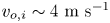 ${v_{o,i}}\sim 4\ \textrm{m}\ {\textrm{s}^{ - 1}}$ (see movie 3), the flame shape and structure is observed to vary following similar initial transitions to that of the previous case (see figure 2c). The initial open-brush-shaped wake flame transitions into an edge-stabilized flame and finally envelops the droplet (similar to that observed for
 ${v_{o,i}}\sim 3\ \textrm{m}\ {\textrm{s}^{ - 1}}$). However, due to the higher co-flow velocity
 $({v_{o,i}}\sim 4\ \textrm{m}\ {\textrm{s}^{ - 1}})$, the enveloped flame then transitions into a wake flame structure but in the opposite (downward) direction (at
 ${\sim} 31\ \textrm{ms}$).
The flame is detached from the droplet and is observed to stabilize in front (upstream) of the accelerating droplet. This configuration will hereby be referred to as the reverse wake flame. The extinction at the rear stagnation point of the falling droplet leads to the transition of the enveloped flame to a reverse wake flame. The reverse wake flame is initially observed to have an edge-stabilized flame structure, whose flame height increases before it transitions into a reverse open-brush shape around  ${\sim} 44\ \textrm{ms}$. The flame height of the reverse open-brush flame initially increases and then flattens, before switching back into a reverse branched-edge-flame configuration around
 ${\sim} 63\ \textrm{ms}$. The reverse edge-stabilized flame then flattens and envelopes around the droplet (
 ${\sim} 96\ \textrm{ms}$). After this point, the flame evolution is similar to that observed for
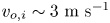 ${v_{o,i}}\sim 3\ \textrm{m}\ {\textrm{s}^{ - 1}}$, where the enveloped flame transitions into an upright branched-edge (edge stabilized) wake flame and then into an open-brush-shaped wake flame (see figure 2c).
The flame evolution observed in all the cases has one forward phase of an upright wake flame transitioning into an enveloped flame and one receding phase wherein the flame tends to transition towards the upright wake configuration (sequence shown in figure 7(d) corresponds to the receding phase). It is to be noted that the droplet velocity continuously increases temporally because of gravity. In case of a near-field wake flame (current experiments), the relative velocity of the bulk flow experienced by the droplet is same as that of the wake flame. Hence, the velocity experienced by the wake flame should always increase with time. However, at the exit of the co-flow tube ( $z = 0$), there is a discontinuity in velocity experienced by the droplet. Before exiting the tube (
 $z = 0$), the droplet experiences the relative velocity (
 ${v_{rel}}$) which is equal to its own velocity of descent, i.e. (
 ${u_{o,i}}\sim 2.47\ \textrm{m}\ {\textrm{s}^{ - 1}}, \textrm{upwards}$). But in the presence of co-flow, as it exits the tube (
 $z = {0^ + }$), the droplet also experiences the co-flow velocity, and hence the relative velocity experienced by the droplet with co-flow is
 ${u_{o,i}} - {v_{o,i}}(\textrm{upwards})$. Because of this discontinuity, the droplet flame has to re-adjust to this sudden jump in the surrounding velocity. This re-adjustment phase is hereby referred to as the ‘non-equilibrium’ regime. This non-equilibrium regime is the forward phase, where the flame tends to transition downwards towards the enveloped state from the wake configuration. Once the droplet flame re-adjusts to the surrounding relative velocity, it then evolves only in response to the temporal evolution of the instantaneous relative velocity (similar to the case without co-flow). This stage is hereafter referred to as the ‘equilibrated’ regime. The receding phase mentioned before corresponds to the equilibrated regime, where the flame tends to transition away from the enveloped state towards the upright wake flame configuration. It is to be noted that
 ${v_{o,i}}$ is the co-flow velocity encountered by the droplet flame initially at
 $z = {0^ + }$ and
 ${v_o}$ is the co-flow velocity for
 $z > 0$, accounting for the laminar jet expansion of the co-flow. The droplet velocity at any given instant is
 ${u_o}$, and
 ${u_{o,i}}$ is the initial droplet velocity at
 $z = 0$. In the analysis presented hereafter, the droplet diameter does not vary temporally, as the droplet flame is in the wake configuration for the majority of the droplet flight time. This can be attributed to the low droplet vaporization rate since less than 2 % of the droplet surface area is exposed to the wake flame (Pandey et al. Reference Pandey, Basu, Vadlamudi, Potnis and Chattopadhyay2020) (see supplementary figure S2). This is also confirmed by Chiu, wherein they showed that the vaporization rate significantly reduces when an enveloped flame transitions to a wake flame (Chiu Reference Chiu2000). In the present experiment, the droplet is observed to be in an enveloped configuration only for a short period of 0.005 s, which accounts for negligible droplet regression.
3.2. Equilibrated regime
The equilibrated regime is the state of the droplet flame, where the droplet flame has fully adjusted to the instantaneous relative velocity ( ${v_{rel}}$), meaning the droplet flame evolves in response to the
 ${v_{rel}}$. As
 ${v_{rel}}$ increases, the flame tends to transition towards the wake configuration from an enveloped state due to forward extinction. Hence, for a given droplet size, the droplet flame attains a unique flame structure and shape corresponding to the instantaneous relative velocity (
 ${v_{rel}}$). Based on current experiments and our previous studies (Pandey et al. Reference Pandey, Basu, Vadlamudi, Potnis and Chattopadhyay2020; Vadlamudi et al. Reference Vadlamudi, Thirumalaikumaran and Basu2021), the flame majorly occurs in three configurations: enveloped flame
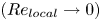 $(R{e_{local}} \to 0)$, edge-stabilized wake flame (
 $5 < R{e_{local}} < 20$) and bluff-body-stabilized open-brush wake flame
 $(20 < R{e_{local}} < 130)$. The next part of this section will focus on the theoretical basis for the flame shape and flame stabilization mechanism for the corresponding wake flame configurations.
3.2.1. Edge-stabilized wake flame
The edge-stabilized wake flame is conjectured to have a similar flame structure to that of a branched-edge flame that is stabilized over a Bunsen burner (Law Reference Law2010). The relative flow around the edge-stabilized wake flame remains attached in the Reynolds number range of  $5 < R{e_{local}} < 20$ without any recirculation in the wake. Hence, it is reasonable to consider the wake flow as concentric fuel and air streams. The flame edge consists of a premixed flame front which tends to propagate upstream and is stabilized due to the local balance of the relative flow velocity scale (
 ${v_{rel}}$) and flame propagation speed (
 $ {\textrm{S}_L}$). Due to the presence of the annular air stream and the central fuel stream, a gradient of fuel concentration exists along the contour of the premixed flame front. Thus, the equivalence ratio (
 $\boldsymbol{\phi }$) continuously changes along the radius from
 $\boldsymbol{\phi } = {\bf 0}$ on the outer edge (oxidizer end) to
 $\boldsymbol{\phi } \gg {\bf 1}$ at the centre. The inner fuel-rich branch of the flame front has
 $\boldsymbol{\phi } \ge {\bf 1}$, whereas the outer fuel-lean branch has
 $\boldsymbol{\phi } < {\bf 1}$ (Ko & Chung Reference Ko and Chung1999; Vadlamudi et al. Reference Vadlamudi, Thirumalaikumaran and Basu2021), see figure 3(a).
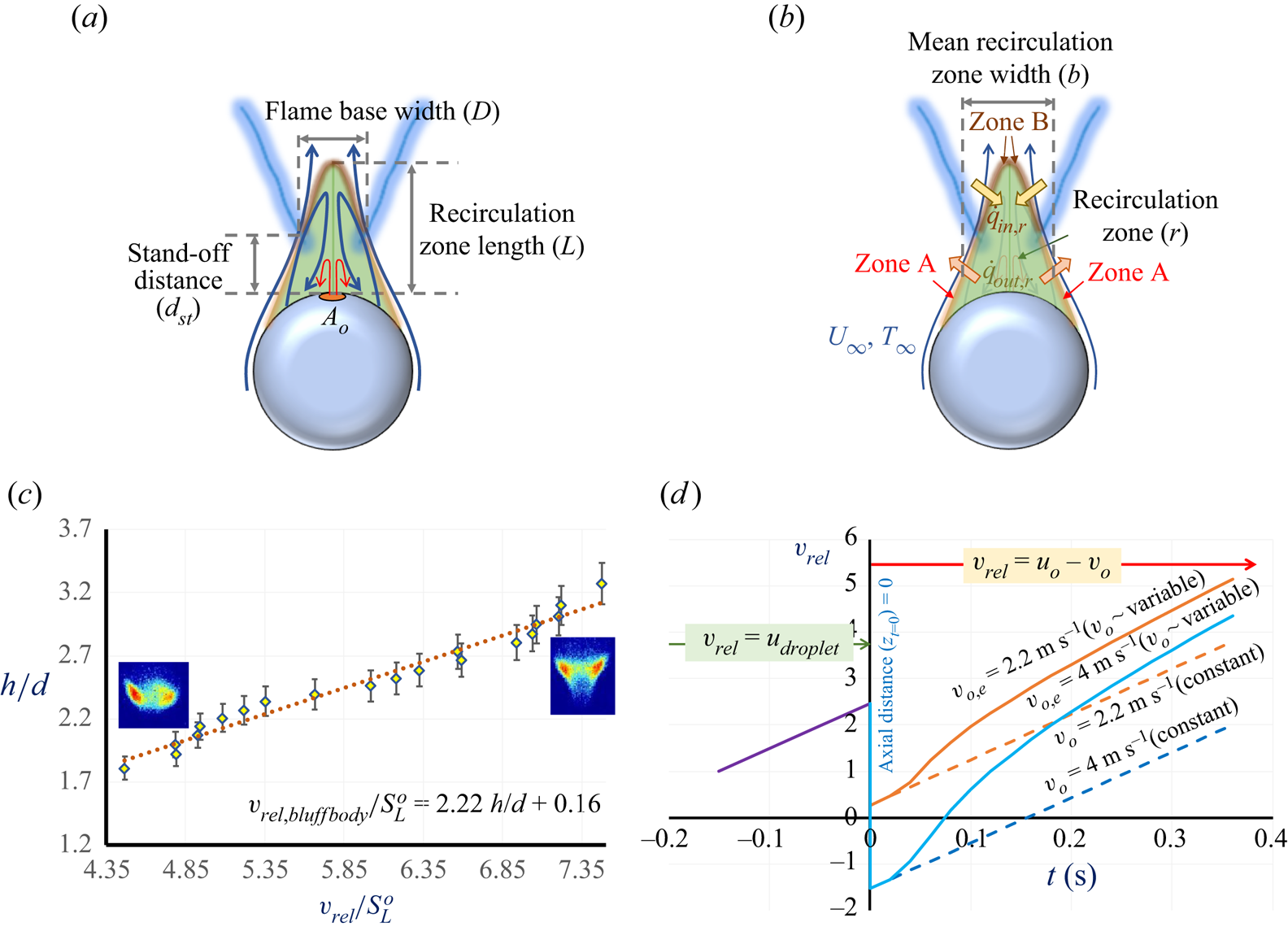
(a) Schematic of edge-stabilized wake flame and edge-flame stabilization. (b) Normalized flame height ( $h/d$) v/s normalized relative flow velocity scale at the droplet (
 ${\tilde{v}_{rel}}\sim {v_{rel}}/S_L^o$). The error bars represent an uncertainty of ±10 %.

However, the portion of the flame which is away from the flame edge is stabilized through the local balance between the flame speed and the component of the flow velocity at the droplet perpendicular to the flame front, as shown in figure 3(a). Hence, balancing the local flame speed ( ${S_L}$) and flow velocity scale relative to the flame (
 ${v_{rel}}$)
 \begin{gather}{v_{rel}}\,\textrm{sin}\,\theta = {S_L},\end{gather}
 \begin{gather}{v_{rel}} = \frac{{{S_L}}}{{\textrm{sin}\,\theta }},\end{gather}
 \begin{gather}{v_{rel}} = {S_L}\sqrt {1 + {{\left( {\frac{{{h}}}{{d/2}}} \right)}^2}} ,\end{gather}
 \begin{gather}{v_{rel}}\sim \frac{h}{d},\end{gather}
 \begin{gather}{v_{rel}} = {c_1}\frac{h}{d} + {c_2}.\end{gather}
After simplifying (3.1), the relation between  ${v_{rel}}$ and
 $h/d$ is obtained as (3.3), which can be approximately expressed as a simplified scaling expression (3.4), assuming linear approximation in the range of
 $0.35 < h/d < 0.8$, where the edge-stabilized wake flame is observed and
 ${d_f}\sim d$ in this range. Further details on the linear approximation can be found in the supplementary material (figure S3). It is to be noted that, beyond
 $Re > 20$, the characteristics of the flow around the droplet change by establishing axisymmetric vortices in the rear stagnation region. Hence, the flame response will also change for
 $Re > 20$ (corresponding normalized local flame height:
 $h/d > 0.8$). For simplicity, the correlation in (3.4) can be rewritten as a linear equation, as shown in (3.5), using coefficients that can be found empirically from experimental data from our previous study for the edge-stabilized wake flame (Vadlamudi et al. Reference Vadlamudi, Thirumalaikumaran and Basu2021). The flame height variation (h) with change in local flow velocity scale relative to the flame (
 ${v_{rel}}$) is found to match with the linear correlation shown in (3.5).
Using the previous experimental data (Vadlamudi et al. Reference Vadlamudi, Thirumalaikumaran and Basu2021), the instantaneous flame height characteristics for the whole range of vrel were measured from the binary images obtained by performing Otsu's thresholding on the flame images, as explained in § 2. For this particular set of experiments, since the flame is stabilized in the far wake, the droplet velocity cannot be used for evaluating the relative bulk flow velocity perceived by the flame (vrel). The flame dynamics is modulated due to the bulk relative flow velocity scale (vrel) experienced by the flame as a result of the net external flow imposition. Furthermore, the bulk velocity scale of the relative flow (vrel) experienced by the wake flame is the direct consequence of the flame descent speed through the quiescent environment in the laboratory reference frame. Thus, the instantaneous relative velocity scale of the bulk flow (vrel) is computed by spatially tracking the instantaneous location of the flame base with time in the laboratory reference frame that is obtained from Otsu's thresholding for the freely falling droplet combustion data of previous experiments without co-flow (Vadlamudi et al.). It is to be noted that the vrel measured is just the scale of the relative velocity of the bulk flow and is a parameter used to characterize the instantaneous flow perceived by the flame. However, the effect of the flow field around the droplet on mixing is considered in the subsequent sections that discuss the flame stabilization mechanisms. Instantaneous droplet diameter is measured from the simultaneous shadowgraphy images. Thus obtained normalized flame height ( $h/d$) from the previous data (Vadlamudi et al. Reference Vadlamudi, Thirumalaikumaran and Basu2021) is plotted against relative flow velocity scale at the droplet (
 ${v_{rel}}$), which is normalized using the laminar flame speed (
 $S_L^o$), as shown in figure 3(b).
The plot shows a linear correlation between  $h/d$ and the
 ${\tilde{v}_{rel}}$ i.e.
 ${v_{rel}}$ normalized with the laminar flame speed (
 $S_L^o$), and can be used to estimate the coefficients of the scaling relation shown in (3.5). The obtained empirical relation is presented in (3.6).
 \begin{equation}\frac{{{v_{rel,EdgeStb}}}}{{S_L^o}} = 0.44\frac{h}{d} + 0.1.\end{equation}
3.2.2. Edge-stabilized wake flame stabilization mechanism
The edge-flame stabilization mechanism has been investigated in this section. The schematic of the heat and mass transfer near the droplet wake and the flame (assumed planar for simplicity) is shown in figure 4(a). Since the edge-stabilized flame in the current experiments stabilizes in the range 9 < Re < 18, the airflow around the droplet is characterized by an attached wake flow (with no recirculation eddies in the wake), similar to the flow over a sphere for 0 < Re < 20, (Kalra, T.R. Reference Kalra and U1971) (see figure 4b). The flow in the wake can be approximated to be analogous to co-axial jets, wherein the inner core stream is fuel, and the outer annular stream is the oxidizer. Figure 4(c) shows the schematic of the co-axial jets analogy and shows the entrainment of the outer jet into the inner jet. The entrained mass increases as the axial distance ( $x$) increases. Assuming an infinite rate chemistry, this now reduces to a species diffusion problem (mixing problem). Our previous schlieren experiments showed that the fuel vapour wake emanates only from the region near the rear stagnation point. This suggests that the vaporization only occurs from the small region (∼2 % of droplet surface area) that is exposed to the wake flame. Since only 2 % of the total droplet surface area (
 ${A_{total}}$) is exposed to the wake flame, the fuel stream is assumed to be originating only from the portion of the droplet with surface area,
 ${A_o}$ (where
 ${A_o}\sim 0.02{A_{total}}$) (Pandey et al. Reference Pandey, Basu, Vadlamudi, Potnis and Chattopadhyay2020). The amount of air entrainment into the fuel stream is calculated using the co-axial jet analogy, which is used to acquire the theoretical value of the equivalence ratio along the axial direction (
 $x$).
(a) The schematic of the heat and mass transfer near the droplet wake and the flame (assumed planar for simplicity). (b) The schematic of expanding jets shows the air entrainment into the fuel stream in the droplet wake. (c) Schematic of co-axial jets depicting entrainment.

Ricou & Spalding (Reference Ricou and Spalding1961) showed that, for entraining fuel jets, the ratio of the mass flux (at a given axial distance) to the initial fuel mass flux at the jet exit is given by (3.7)
 \begin{equation}\frac{1}{{{Y_F}}} = \frac{{\dot{m}_F + {{\dot{m}}_{Ox}}}}{\dot{m}_F}\sim \left( {\frac{x}{{{d_o}}} } \right){\left( {\frac{{{\rho_{out}}}}{{{\rho_{in}}}}} \right)^{1/2}},\end{equation}
where the outer flow is the oxidizer (air), and the inner flow is the fuel vapour. For the current co-axial jet approximation, the axial variation of the equivalence ratio can be estimated from the axial variation of fuel-air ratios obtained using the entrainment relations of co-axial jets from the literature (Villermaux & Rehab Reference Villermaux and Rehab2000; Schumaker & Driscoll Reference Schumaker and Driscoll2008; Bennewitz et al. Reference Bennewitz, Schumaker, Lietz and Kastengren2021). The fuel mole fraction ( ${X_F}$) of the jet at a given axial location (
 $x$) can be scaled using the relation given below (3.8):
 \begin{equation}{X_F}\sim {\left( {\frac{x}{{{d_o}}}{M^{1/2}}} \right)^{ - 1}}\sim {\left( {\frac{x}{{{d_o}}}{{\left( {\frac{{{\rho_{out}}}}{{{\rho_{in}}}}} \right)}^{1/2}}\left( {\frac{{{v_{out}}}}{{{v_{in}}}}} \right)} \right)^{ - 1}},\end{equation}
where  ${d_o}$ is the diameter corresponding to the droplet surface area
 ${A_o}$, assuming
 ${A_o}$ to be a flat circle (since
 ${A_o} \ll {A_{total}}$) and M is the momentum flux ratio of outer and inner jets
 \begin{equation}M = \left( {\frac{{{\rho_{out}}}}{{{\rho_{in}}}}} \right){\left( {\frac{{{v_{out}}}}{{{v_{in}}}}} \right)^2},\end{equation}
where  ${v_{out}}$ is considered to be equal to the average surrounding relative flow velocity (
 ${v_{rel}}$) where edge-stabilized wake flames are observed.
The velocity scale of the fuel vapour stream ( ${v_{in}}$) can be estimated by evaluating the droplet evaporation rate. Since it has been established that fuel vaporization only occurs from the small surface area (
 ${A_o}$) on the droplet surface near the rare stagnation point, the pool-fire energy balance model by Yip, Haelssig & Pegg (Reference Yip, Haelssig and Pegg2021) can be used to estimate the burning rate of the fuel droplet (see figure 3a). A global energy balance around the evaporating droplet can be written down as heat transfer due to net conduction
 $({\dot{Q}_{cond}})$, convection
 $({\dot{Q}_{conv}})$, radiation
 $({\dot{Q}_{r,f - d}})$ from the flame to the liquid pool (
 ${A_o}$) and the radiative heat loss to the surroundings
 $({\dot{Q}_{r,d - a}})$, as shown below
 \begin{equation}{\dot{m}_F}(\Delta {H_v}) = {\dot{Q}_{cond}} + {\dot{Q}_{conv}} + {\dot{Q}_{r,f - d}} + {\dot{Q}_{r,d - a}},\end{equation}
where  ${\dot{m}_F}$ is the fuel evaporation rate and
 $\Delta {H_v}$ is the enthalpy of vaporization of the fuel. Using the Fourier's heat conduction equation,
 ${\dot{Q}_{cond}}\sim k{A_o}(({T_{ad}} - {T_s})/{d_{st}})$ is obtained to be
 $0.026\ \textrm{W}$.
The radiative heat transfer term is estimated using  ${\dot{Q}_{r,f - d}}\sim \sigma {F_{df}}{A_o}{\varepsilon _D}(T_{ad}^4 - T_s^4)$, where
 $\sigma $ is the Stefan–Boltzmann constant,
 ${\varepsilon _D}$ is the emissivity of the liquid fuel and
 ${F_{df}}$ (view factor) accounts for a fraction of radiative energy from the droplet that is interacting with the flame. The view factor
 ${F_{df}}$ is evaluated assuming a flame with area
 ${A_f}$ and the exposed droplet surface area
 ${A_o}$ as parallel discs separated by the stand-off distance (
 ${d_{\boldsymbol{st}}}$). The view factor (
 ${F_{df}}$) is then given as
 \begin{equation}{F_{df}} = \frac{1}{2}\left[ {S - {{\left[ {{S^2} - 4{{\left( {\frac{{{d_f}}}{{{d_O}}}} \right)}^2}} \right]}^{1/2}}} \right],\quad \textrm{where}~S = \frac{{d_o^2 + d_f^2 + 4d_{st}^2}}{{d_o^2}}.\end{equation}
Then,  ${\dot{Q}_{r,f - d}}$ is obtained to be 0.072 W, and similarly, the heat loss from the droplet is obtained to be
 ${\dot{Q}_{r,d - a}}\sim \sigma {A_o}{\varepsilon _D}(T_\infty ^4 - T_s^4) ={-} 0.00034\ \textrm{W}$.
The formulation of the pure convective heat flux on the surface of the pool in steady pool fires by Spalding (Reference Spalding1953) can be extended to evaluate  ${\dot{Q}_{conv}}$, as shown below
 \begin{equation}{\dot{Q}_{conv}} =
{A_o}\frac{{\mathop{h}\limits^{\prime}}}{{{C_p}}}\left[ {
\frac{{\Delta {H_c}({\chi_a} - {\chi_r})}}{{{\chi_a} r}}
- {C_p}({T_s} - {T_\infty })} \right]\frac{\lambda
}{{{e^\lambda } -
1}}.\end{equation}
Where  $\mathop{h}\limits^{\prime}$ is the coefficient of convective heat transfer,
 ${C_p}$ is the specific heat capacity of the ambient,
 $\Delta {H_c}$ is the enthalpy of combustion of fuel,
 ${\chi _a}$ is the combustion efficiency,
 ${\chi _r}$ is the radiative fraction, r is the stoichiometric air-to-fuel mass ratio and
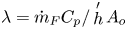 $\lambda = {\dot{m}_F}{C_p}/\mathop h\limits^{\prime}{A_o}$. For the convective heat transfer from a flat pool, the convective heat transfer coefficient
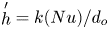 $\mathop h\limits^{\prime} = k(Nu)/{d_o}$ can be evaluated using the Nusselt number (Nu) correlation that is expressed in terms of Rayleigh number (
 $Ra$), for the natural convection over a horizontal plate, i.e.
 \begin{equation}Nu = 0.54{(Ra)^{1/4}}\sim 5.44,\quad \textrm{where}~Ra = \frac{{g\beta (\Delta T)d_o^3}}{{{\nu ^2}}}Pr.\end{equation}
Then the convective heat transfer coefficient ( $\mathop h\limits^{\prime} $) is substituted in the (3.12), to get
 \begin{equation}{\dot{Q}_{conv}} = 0.2316\frac{\lambda }{{{e^\lambda } - 1}},\quad \textrm{where}~\lambda = 7755389.8{\dot{m}_F}.\end{equation}
Substituting for all the terms in (3.10), an expression is obtained with  ${\dot{m}_F}$ as the only unknown
 \begin{equation}{\dot{m}_F} = (2.725 \times {10^{ - 7}}) + (6.444 \times {10^{ - 7}})\left( {\frac{\lambda }{{{e^\lambda } - 1}}} \right).\end{equation}
Solving the above equation iteratively, the rate of evaporation at the droplet surface  $({\dot{m}_F})$ is evaluated.
Using the evaporation mass flux  $({\dot{m}_F})$, the order of magnitude of the vapour velocity scale (
 ${v_{in}}$) is obtained to be
 ${\sim} 0.21\ \textrm{m}\ {\textrm{s}^{ - 1}}$. The value of
 ${v_{in}}$ obtained is found to be of a similar order of magnitude as the natural convection velocity scale (
 ${v_{NC}}\sim \sqrt {g\beta \Delta Td} $).
Finally, the corresponding fuel–air mass ratio at a given axial distance in terms of the fuel mass fraction ( ${Y_F}$) is calculated using (3.16)
 \begin{equation}\frac{{{{\dot{m}}_F}}}{{{{\dot{m}}_{Ox}}}} = \frac{1}{{{Y_F} - 1}}.\end{equation}
The mean equivalence ratio ( ${\boldsymbol{\phi }_m}$) at a given axial distance (x), is then estimated as the ratio of the fuel–air ratio at a given location (x) to the stoichiometric fuel–air ratio
 \begin{equation}{\boldsymbol{\phi }_m} = \frac{{\dfrac{{{{\dot{m}}_F}}}{{{{\dot{m}}_{Ox}}}}}}{{{{\left( {\dfrac{{{{\dot{m}}_F}}}{{{{\dot{m}}_{Ox}}}}} \right)}_{St}}}}.\end{equation}
Here,  ${\boldsymbol{\phi }_{\boldsymbol{m}}}$ is observed to reduce as the axial distance from the droplet surface increases. The axial variation of the equivalence ratio is plotted in figure 5(a). Using this, the value of the mean equivalence ratio (
 ${\boldsymbol{\phi }_m}$) at the axial location of the flame base (
 $x = {d_{\boldsymbol{st}}}$) can be evaluated. This will be used further to evaluate the radial variation of the equivalence ratio necessary for gain further insights into edge-flame stabilization.
(a) Mean equivalence ratio ( ${\boldsymbol{\phi }_{\boldsymbol{m}}}$) variation plotted against normalized axial distance (
 $x/d$). (b) The schematic depiction of the radial and axial coordinates with respect to the edge-stabilized flame. (c) Radial variation of equivalence ratio (
 $\boldsymbol{\phi }$) and the variation of corresponding flame temperatures
 ${T_g}$ and
 ${T_{eq}}$ plotted against normalized radial distance (
 $\tilde{r} \sim r/{r_o}$) at the axial flame location.

3.2.3. Radial variation of the local equivalence ratio  $(\hat{\boldsymbol{\phi }})$

The equivalence ratio  $({\boldsymbol{\phi }_{\boldsymbol{m}}})$ estimated at a given axial distance (x) in the previous section is the mean value of
 $\boldsymbol{\phi }$ in that plane situated at an axial distance (x). However, the radial profile of the local equivalence ratio
 $(\hat{\boldsymbol{\phi }})$ within that plane is dependent on both the centreline equivalence ratio
 $({\hat{\boldsymbol{\phi }}_{\boldsymbol{r} \to {\bf 0}}} = \boldsymbol{\phi}_c)$ and the far-field equivalence ratio
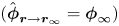 $({\hat{\boldsymbol{\phi }}_{\boldsymbol{r} \to {\boldsymbol{r}_\infty }}} = {\boldsymbol{\phi }_\infty })$. It is known that the far-field equivalence ratio
 ${\boldsymbol{\phi }_\infty }\mathop \to \limits^{\boldsymbol{ }} \boldsymbol{ }0$ due to the absence of fuel in the free stream. Since the length of the inner potential core is less than
 ${d_{\boldsymbol{st}}}$ for the velocity ratio (Larsson et al. Reference Larsson, Lycksam, Lundström and Marjavaara2020), the centreline composition at the axial location (
 $x = {d_{\boldsymbol{st}}}$) will not be pure fuel. Thus, the local centreline equivalence ratio is unknown and will be estimated in this section. Since, experimentally, the radial location of the base of the edge flame is known (
 $r = {r_{\boldsymbol{f}}}$), it is reasonable to assume the corresponding equivalence ratio at the flame base to be stoichiometric
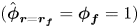 $({\hat{\boldsymbol{\phi }}_{\boldsymbol{r} = {\boldsymbol{r}_{\boldsymbol{f}}}}} = {\boldsymbol{\phi }_{\boldsymbol{f}}} = 1)$. A Gaussian profile is shown to be a reasonable fit for the radial mixing profiles (Hotz et al. Reference Hotz, Haas, Wachter, Fleck and Kolb2023) since the variation of the mixture fraction of the fuel vapour is axisymmetric, and it peaks at the centre and approaches zero asymptotically on either side in the free stream. Since the
 $\hat{\boldsymbol{\phi }}$ value at two radial locations (i.e.
 $r = {r_{\boldsymbol{f}}}\ \textrm{and}~{r_\infty }$) is known, the three-point generated Gaussian function (Li, Valentine & Rana Reference Li, Valentine and Rana1999) can be used to generate the radial variation of
 $\hat{\boldsymbol{\phi }}$ in the plane (at
 $x = {d_{\boldsymbol{st}}}$), by assuming values for
 ${\boldsymbol{\phi }_{\boldsymbol{c}}}$ (centreline equivalence ratio). The three-point generated Gaussian function equation with respect to the three points
 $({r_c},{\boldsymbol{\phi }_c})$,
 $({r_f},{\boldsymbol{\phi }_f})$ and
 $({r_\infty },{\boldsymbol{\phi }_\infty })$ is shown below
 \begin{equation}\hat{\boldsymbol{\phi }}(\boldsymbol{r}) = \frac{A}{{\sqrt {2{\rm \pi} {\sigma ^2}} }}\,\textrm{exp}\left[ { - \frac{{{{(r - \mu )}^2}}}{{2{\sigma^2}}}} \right],\end{equation}
where
 \begin{gather}A = \sqrt {2{\rm \pi} {\sigma ^2}} {({\boldsymbol{\phi }_c}{\boldsymbol{\phi }_f}{\boldsymbol{\phi }_\infty })^{1/3}}\,\textrm{exp}\left[ {\frac{{{{({r_c} - \mu )}^2} + {{({r_f} - \mu )}^2} + {{({r_\infty } - \mu )}^2}}}{{6{\sigma^2}}}} \right],\end{gather}
 \begin{gather}\sigma = \sqrt {\frac{{({r_c} - {r_\infty })({r_f} - {r_c})({r_\infty } - {r_f})}}{{2\,\textrm{ln}[\boldsymbol{\phi }_c^{{r_\infty } - {r_f}}\boldsymbol{\phi }_f^{{r_c} - {r_\infty }}\boldsymbol{\phi }_\infty ^{{r_f} - {r_c}}]}}} ,\quad \mu = \frac{{\textrm{ln}[\boldsymbol{\phi }_c^{r_\infty ^2 - r_f^2}\boldsymbol{\phi }_f^{r_c^2 - r_\infty ^2}\boldsymbol{\phi }_\infty ^{r_f^2 - r_c^2}]}}{{\textrm{ln}[\boldsymbol{\phi }_c^{{r_\infty } - {r_f}}\boldsymbol{\phi }_f^{{r_c} - {r_\infty }}\boldsymbol{\phi }_\infty ^{{r_f} - {r_c}}]}},\end{gather}
where  $\mu ,\sigma $ are the mean and standard deviation of the Gaussian profile. The radial profiles of
 $\hat{\boldsymbol{\phi }}$ were obtained for different values of
 ${\boldsymbol{\phi }_c} \in (0,6)$. Then, the average value of the stoichiometric ratio (
 ${\boldsymbol{\phi }_{avg,{d_{\boldsymbol{st}}}}}$) is evaluated for each of the profiles that are obtained for different values of
 ${\boldsymbol{\phi }_c} \in (0,6)$ using (3.18) (for the plane
 $x = {d_{st}}$, marked by dotted blue line in figure 5b). Thus, the correct value of the centreline equivalence ratio
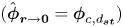 $({\hat{\boldsymbol{\phi }}_{\boldsymbol{r} \to {\bf 0}}} = {\boldsymbol{\phi }_{c,{d_{\boldsymbol{st}}}}})$ for
 $x = {d_{st}}$ is evaluated by equating the average radial equivalence ratio
 $({\boldsymbol{\phi }_{avg,{d_{\boldsymbol{st}}}}})$ values obtained in this section with the already established mean equivalence ratio corresponding to the axial location,
 $x = {d_{st}}$
 $({\boldsymbol{\phi }_{m,(x = {d_{\boldsymbol{st}}})}})$, which was evaluated in the previous section (see (3.17)) using the coaxial jet formulation.
Thus, after obtaining the correct value for  ${\boldsymbol{\phi }_c}$, the radial variation of
 $\hat{\boldsymbol{\phi }}$ in the axial plane
 $x = {d_{st}}$ is obtained in the form of a Gaussian profile and is plotted in figure 5(c) against the radial distance normalized by the radius of the fuel jet i.e.
 $\tilde{r}\sim r/{r_{\boldsymbol{o}}}$. The plot shows that the equivalence ratio
 $(\hat{\boldsymbol{\phi }})$ peaks at the centre and decreases in the radially outward direction, asymptotically reaching zero in the free stream. The radial location (
 $r = {r_{\boldsymbol{f}}}$) corresponding to
 $\hat{\boldsymbol{\phi }} = 1$ is the location of the flame base obtained experimentally, where the local flame propagation speed (
 ${S_E}$) is maximum, and it matches the flow velocity at the droplet, leading to flame stabilization (as shown in figure 3a). At the flame base, a premixed edge-stabilized flame propagates upstream with respect to the upstream flow, containing two branches: fuel rich and fuel lean. As shown in figure 5(c), from the flame base location (
 $r = {r_{\boldsymbol{f}}}$), the equivalence ratio
 $(\hat{\boldsymbol{\phi }})$ becomes less than 1 and decreases in the radially outward direction, forming a fuel-lean region, whereas, in the radially inward direction, the local equivalence ratio
 $(\hat{\boldsymbol{\phi }})$ becomes more than unity and increases radially inward from the flame base location (
 $r = {r_{\boldsymbol{f}}}$). This leads to a gradient of the local equivalence ratio
 $(\hat{\boldsymbol{\phi }})$ along the flame branch on either side of the stoichiometric location
 $(\hat{\boldsymbol{\phi }} = 1)$, forming a fuel-rich branch on the
 $\hat{\boldsymbol{\phi }} > 1$ side (
 $r < {r_{\boldsymbol{f}}}$) and fuel-lean branch on the
 $\hat{\boldsymbol{\phi }} < 1$ side (
 $r > {r_{\boldsymbol{f}}}$). This agrees with the literature on edge-stabilized flames, where the flame front propagates upstream against the flow-field having a mixture stratification (Chung Reference Chung2007).
3.2.4. Flame temperature estimation using global reaction (simplistic model)
The equivalence ratio ( $\boldsymbol{\phi }$) can now be used to calculate the theoretical flame temperature (
 ${T_g}$). The stoichiometric equation has been modified to accommodate both the excess air (
 $\boldsymbol{\phi } < 1$) and excess fuel (
 $\boldsymbol{\phi } > 1$) conditions. The global stoichiometric equation for the combustion of dodecane is presented in (3.19). An extra ‘a’ moles of air are added to the stoichiometric equation to represent fuel-lean combustion, obtaining (3.20). Similarly, for fuel-rich combustion, ‘
 ${f_e}$‘ moles of fuel are added to the stoichiometric equation. For simplicity, CO formation and its dissociation reactions are neglected in the fuel-rich combustion case and is shown in (3.21)
 \begin{gather}{\textrm{C}_{12}}{\textrm{H}_{26}} + \frac{{37}}{2}({\textrm{O}_2} + 3.76{\textrm{N}_2}) \to 12\textrm{C}{\textrm{O}_2} + 13{\textrm{H}_2}\textrm{O} + \left( {\frac{{37}}{2}} \right)3.76{\textrm{N}_2},\end{gather}
 \begin{gather}{\textrm{C}_{12}}{\textrm{H}_{26}} + \left( {\frac{{37}}{2} + a} \right)({\textrm{O}_2} + 3.76{\textrm{N}_2}) \to 12\textrm{C}{\textrm{O}_2} + 13{\textrm{H}_2}\textrm{O} + \left( {\frac{{37}}{2} + a} \right)3.76{\textrm{N}_2} + a{\textrm{O}_2},\end{gather}
 \begin{gather}(\,{f_e} + 1){\textrm{C}_{12}}{\textrm{H}_{26}} + \left( {\frac{{37}}{2}} \right)({\textrm{O}_2} + 3.76{\textrm{N}_2}) \to 12\textrm{C}{\textrm{O}_2} + 13{\textrm{H}_2}\textrm{O} + \left( {\frac{{37}}{2}} \right)3.76{\textrm{N}_2}\nonumber\\ + \ \,{f_e} {\textrm{C}_{12}}{\textrm{H}_{26}},\end{gather}
 \begin{gather}(\,{f_e} + 1){\textrm{C}_{12}}{\textrm{H}_{26}} + \left( {\frac{{37}}{2} + a} \right)({\textrm{O}_2} + 3.76{\textrm{N}_2}) \to 12\textrm{C}{\textrm{O}_2} + 13{\textrm{H}_2}\textrm{O} + \left( {\frac{{37}}{2} + a} \right)3.76{\textrm{N}_2}\nonumber\\ +\ \, a{\textrm{O}_2} + {f_e}{\textrm{C}_{12}}{\textrm{H}_{26}}.\end{gather}
A combined representative chemical equation is considered, as shown in (3.22), where  ${f_e} = 0$,
 $a = 0$ and
 $a = {f_e} = 0$ represents fuel-lean, fuel-rich and stoichiometric conditions, respectively.
A global energy balance of the above equation set (a simplified approach) can be used to estimate the approximate flame temperature ( ${T_g}$). The resulting equation is shown in (3.23)
 \begin{align}
{T_g} = \frac{\begin{array}{l}(\alpha + 1)h_{f,DD}^o - 12h_{f,C{O_2}}^o - 13h_{f,{H_2}O}^o + {C_{p,DD}}({T_{wb}} - {T_\infty })\\
\quad +\ {T_\infty }\left({12{C_{p,C{O_2}}} + 13{C_{p,{H_2}O}} + \left(
{\dfrac{{37}}{2} + a} \right)3.76{C_{p,{N_2}}} +
a{C_{p,{O_2}}} + \alpha {C_{p,DD}}} \right)\end{array}}
{12{C_{p,C{O_2}}} + 13{C_{p,{H_2}O}} + \left(
{\dfrac{{37}}{2} + a} \right)3.76{C_{p,{N_2}}} +
a{C_{p,{O_2}}} + \alpha
{C_{p,DD}}},\end{align}
where  $a = {\textstyle{{37} \over 2}}[(\alpha + 1)/\phi - 1]$ and
 ${f_e} = 0$ (for the fuel-lean case);
 ${f_e} = (1 + 2a/37)\phi $ and
 $a = 0$ (for the fuel-rich case);
 ${f_e} = 0$ and
 $a = 0$ (for the stoichiometric case). Using (3.22),
 ${T_g}$ has been calculated for different values of
 $\boldsymbol{\phi }$ in the radial direction.
3.2.5. Equilibrium flame temperature estimation using a reduced reaction mechanism
To supplement the temperature estimation from the aforementioned simplistic model, a detailed equilibrium estimation was performed considering the reduced mechanism of n-dodecane in the Chemkin software. The reduced mechanism includes the intermediate species, radicals as well as the dissociation of heavy molecules. The skeleton model is based on the lumped POLIMI (an open source reaction kinetics mechanism by researchers at Politecnico di Milano) pyrolysis and oxidation mechanism of hydrocarbon fuels (Ranzi et al. Reference Ranzi, Frassoldati, Stagni, Pelucchi, Cuoci and Faravelli2014), and the model used consists of 130 species and 2323 reactions (Ranzi et al. Reference Ranzi, Frassoldati, Stagni, Pelucchi, Cuoci and Faravelli2014; Stagni et al. Reference Stagni, Cuoci, Frassoldati, Faravelli and Ranzi2014, Reference Stagni, Frassoldati, Cuoci, Faravelli and Ranzi2016).
The equilibrium flame temperature ( ${T_{eq}}$) is calculated at different equivalence ratios and is plotted against the radial distance alongside the flame temperature estimate (
 ${T_g}$) from the simplified model in figure 5(c). The
 ${T_{eq}}$ and
 ${T_g}$ values are found to be in a similar range at the stoichiometric conditions (
 $\boldsymbol{\phi } = 1$).
The radial variation of the flame temperature (both  ${T_g}$ and
 ${T_{eq}}$) (see figure 5c) peaks near the flame base location (
 $r = {r_{\boldsymbol{f}}}$), corresponding to the stoichiometric condition, i.e.
 $\hat{\boldsymbol{\phi }} = 1$. The flame temperature is observed to be lower on either side of the flame base location (
 $r = {r_{\boldsymbol{f}}}$), hence leading to lower flame propagation velocities on either side, both on the fuel-rich (
 $r < {r_{\boldsymbol{f}}}$) and fuel-lean (
 $r > {r_{\boldsymbol{f}}}$) branches. Due to the lower flame propagation speeds on the fuel-rich and fuel-lean branches, the flame self-adjusts its orientation based on the local
 $\hat{\boldsymbol{\phi }}$ value, as shown in figures 3(a) and 5(b,c), which is also observed experimentally. The concentration gradient at the flame location
 $(\textrm{d}{Y_F}/\textrm{d}{\tilde{r}_{\boldsymbol{\phi } = {\bf 1}}})$ can be obtained from the radial profile of the equivalence ratio variation, which can be used to evaluate the edge-flame propagation speed (
 ${S_E}$) using the scaling
 ${S_E}/S_{L_{\boldsymbol{\phi } = {\bf 1}}}^o\sim 1/(\textrm{d}{Y_F}/\textrm{d}\tilde{r})$, for any given fuel using the aforementioned correlation if the local edge-flame orientation is accurately known, as shown by Chung (Reference Chung2007). However, such measurements are beyond the scope of current experiments.
3.2.6. Bluff-body-stabilized wake flame
The relative flow around the bluff-body-stabilized wake flame is characterized by an axisymmetric vortical structure near the rear stagnation region in the Reynolds number range observed in current experiments  $(20 < R{e_{local}} < 60)$. The open-brush bluff-body-stabilized wake flame is stabilized at the recirculation zone near the rear stagnation point of the fuel droplet (Pandey et al. Reference Pandey, Basu, Vadlamudi, Potnis and Chattopadhyay2020). The flame is fully premixed due to the presence of the recirculation zone that enhances the mixing of fuel and oxidizer. In wake configuration, only around 2 % of the total droplet surface area is exposed to the flame. It can be assumed that the fuel will vaporize only from the small circular region (
 ${A_o}$) of diameter
 ${d_o}$, near the rear stagnation point (Pandey et al. Reference Pandey, Basu, Vadlamudi, Potnis and Chattopadhyay2020) (see figure 6a). The flame is observed to have a quiescent open-brush-like shape similar to that reported in our previous studies (Pandey et al. Reference Pandey, Basu, Vadlamudi, Potnis and Chattopadhyay2020), where the burning droplet has a long laminar wake with no detectable flow fluctuations. This can be explained using the vorticity transport equation given below
 \begin{equation}\frac{{\textrm{D}\omega }}{{\textrm{D}t}} = (\omega \boldsymbol{\cdot }\boldsymbol{\nabla })v - \omega (\boldsymbol{\nabla }\boldsymbol{\cdot }v) + \frac{{\boldsymbol{\nabla }\rho \times \boldsymbol{\nabla }P}}{{{\rho ^2}}} + \vartheta {\nabla ^2}\omega ,\end{equation}
where  $\omega $ is the vorticity, v is the relative flow velocity,
 $\rho $ is the fluid density and P is pressure. The first term on the right-hand side of (3.24) is the vortex stretching term, the second term is the gas expansion term (which can be neglected due to the incompressible flow assumption), the third term represents the vorticity generation due to baroclinic torque and the last term contributes for the viscous dissipation effects. For axisymmetric, incompressible and isobaric conditions, all the terms except the last viscous dissipation term can be assumed to be negligible. It is to be noted that the wake of a burning droplet is at elevated temperatures due to the presence of the flame, which leads to a substantial increase in kinematic viscosity (
 $\vartheta $) by an order of
 ${\sim} O({10^1})$. The high-temperature flame present in the droplet wake modifies the flow field in the wake region due to the hot exhaust gases. This open-brush-shaped flame closely resembles a laminar premixed jet flame (Pandey et al. Reference Pandey, Basu, Vadlamudi, Potnis and Chattopadhyay2020), exhibiting an open tip with a premixed structure due to intense mixing in the recirculation zone. Hence, assuming a point momentum source, the round jet analogy (Schlichting Reference Schlichting1933; Tyler Landfried et al. Reference Tyler Landfried, Jana and Kimber2015) is applied, which suggests that the jet half-width is proportional to
 $R{e^{ - 1}}$ and it also increases linearly with the axial distance (
 $x$). This is mathematically expressed as follows:
 \begin{equation}\frac{{{d_f}(x = {x_1})}}{{{d_o}}} = \frac{{C{x_1}}}{{Re}},\end{equation}
where  ${d_o}$ is the initial jet width at the rear stagnation point,
 ${d_f}$ is the jet width at an axial distance of
 ${x_1}$ from the rear stagnation point and
 $Re$ is the Reynolds number of the relative flow based on
 ${d_o}$. Equation (3.25) suggests that, for a given
 $Re$, the flame width increases linearly in the axial direction. Consider flame heights
 ${h_1}$,
 ${h_2}$ and the corresponding flame widths
 ${d_{f,1}}$,
 ${d_{f,2}}$ at two different velocities
 ${v_{rel,1}}$ and
 ${v_{rel,2}}$, respectively. Substituting the values in (3.25) and taking the ratio of the two equations yields
 \begin{equation}\frac{{{d_{f,1}}}}{{{d_{f,2}}}} = \frac{{{h_1}}}{{{h_2}}}\frac{{R{e_2}}}{{R{e_1}}}\,\mathop \Rightarrow \limits^{ } \,\frac{{{d_{f,1}}}}{{{d_{f,2}}}}\frac{{{h_2}}}{{{h_1}}} = \frac{{{v_{rel,2}}}}{{{v_{rel,1}}}}.\end{equation}
Equation (3.26) shows that the flame width is inversely proportional to the relative flow velocity, whereas the flame height is directly proportional to the relative flow velocity. The flame height can be normalized using the instantaneous droplet diameter ( $d$). Hence, the relation between the normalized flame height (
 $h/d$) with the relative flow velocity is obtained to be
 \begin{equation}{v_{rel}}\sim \frac{h}{d}.\end{equation}
For simplicity, this proportionality can be rewritten as a linear equation using empirical constants  ${s_1}$ and
 ${s_2}$ as presented in (3.28)
 \begin{equation}{v_{rel}} = {s_1}\left( {\frac{h}{d}} \right) + {s_2}.\end{equation}
From our previous experimental data (Pandey et al. Reference Pandey, Basu, Vadlamudi, Potnis and Chattopadhyay2020), the instantaneous flame height characteristics for the whole range of vrel were obtained using Otsu's thresholding on the flame images. Thus, the obtained relative flow velocity is normalized with the laminar flame speed ( ${v_{rel}}/S_L^o$) and is plotted against the normalized flame height
 $(h/d)$ in figure 6(c). The error bars in the plot correspond to the flame height variation (< ±10 %) within each bin containing multiple data points from multiple runs considered in a similar range of relative velocity or flame height value. The plot shows a linear correlation between
 $h/d$ and the
 ${v_{rel}}$ normalized with the laminar flame speed (
 $S_L^o$). The data can be used to estimate the coefficients of (3.28). The obtained empirical relation is presented in (3.29)
 \begin{equation}\frac{{{v_{rel,bluffbody}}}}{{S_L^o}} = 2.22\frac{h}{d} + 0.16.\end{equation}
(a) Schematic of bluff-body-stabilized wake flame. The flame is represented by the blue colour, and the yellow line represents the edge of the recirculation zone. The schematic of flow inside the recirculation zone is shown using arrows (blue for air and red for the fuel stream). (b) Schematic showing heat transfer into and out of the recirculation zone using arrow marks. (c) Normalized flame height ( $h/d$) v/s normalized relative flow velocity at the droplet (
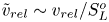 ${\tilde{v}_{rel}} \sim {v_{rel}}/S_L^o$). The error bars represent an uncertainty of ±10 %. (d) The instantaneous velocity experienced by the droplet (
 ${v_{rel, inst}}$) plotted against time after exit (t) at co-flow velocities 2.2 and4 m s−1 for
 ${\textrm{v}_o} = \textrm{const}\textrm{.}$ (
 ${v_{o,i}}$) and
 ${v_o}$ variable along the axial distance (
 $z$) from the co-flow tube.
3.2.7. Bluff-body wake flame stabilization mechanism
In current experiments, for the bluff-body-stabilized wake flame, the relative velocity between the surrounding air and the droplet varies between 0.65 and 2 m s−1. The corresponding Re based on the droplet diameter (d) varies between 29 and 100. In this Re range (20 < Re < 130), airflow past a sphere (droplet) establishes a steady symmetrical vortical structure in the droplet wake (Taneda Reference Taneda1956; Goldburg & Florsheim Reference Goldburg and Florsheim1966; Kalra, T.R. Reference Kalra and U1971; Sakamoto & Haniu Reference Sakamoto and Haniu1990). Beyond this, low-frequency wave-like oscillations ensue (for Re < 270) (Taneda Reference Taneda1956; Sakamoto & Haniu Reference Sakamoto and Haniu1990). The regime considered in the current experiments falls well within the range where steady recirculation vortices are expected in the droplet wake.
Results from the experimental and numerical studies (Taneda Reference Taneda1956; Kalra, T.R. Reference Kalra and U1971; Fornberg Reference Fornberg1988; Dandy & Dwyer Reference Dandy and Dwyer1990; Lee Reference Lee2000) show that the wake length from the droplet centre varies linearly with log(Re) (supplementary figure S4). Thus, the wake length is expected to vary between 4.8 and 3 mm, corresponding to the Re range. At a given instance, a quasi-steady approximation can be used to estimate the wake flame stand-off distance ( ${d_{st}}$) (figure 6a). The outer air vortical structures in the wake region force the vaporized fuel stream to curl and form a counter-rotating vortex. The interaction between the air and fuel vortex ensures the mixing of the constituent reactants resulting in a premixed wake flame stabilized near the recirculation zone. Vortical structures inside the recirculation zone promote the exchange of mass, momentum and energy with the entraining air stream flow.
Following a similar procedure as proposed by Kundu et al. (Reference Kundu, Banerjee and Bhaduri1977), a simplified theoretical model for two-dimensional bluff-body-stabilized premixed flames is used to estimate the flame stand-off distance ( ${d_{st}}$).
The mass exchange rate at the recirculation zone boundary ( ${\dot{m}_e}$) is obtained as follows:
 \begin{equation}{\dot{m}_e}\sim \frac{{{\rho _r}{V_R}}}{{{\tau _r}}},\end{equation}
where  ${\rho _r}$ is the average density of the fuel–air mixture inside the recirculation zone whose volume is
 ${V_R}$ (3.31) and
 ${\tau _r}$ is the mean residence time of the flow inside the volume
 \begin{equation}{V_R} = {F_{RV}} \cdot L \cdot b.\end{equation}
Where  ${F_{RV}}$ is the shape factor, and L, b are the dimensions of the recirculation zone. The mean residence time can be estimated as follows (Kundu et al. Reference Kundu, Banerjee and Bhaduri1977):
 \begin{equation}{\tau _r} = 104\frac{b}{{{U_\infty }}},\end{equation}
where  ${U_\infty }$ is the mean velocity of the premixed reactants into the flame front. The relation is valid for a wide range of bluff-body dimensions and equivalence ratios and is almost unchanged for bluff bodies with different shapes (Bovina Reference Bovina1958). Using the above relations (3.31 and 3.32), (3.30) can be simplified as
 \begin{equation}{\dot{m}_e}\sim \frac{{{\rho _r}{F_{RV}}{U_\infty }}}{K}L.\end{equation}
If the flame is stabilized at an axial distance of  $x = {d_{st}}$ in the droplet wake, it divides the lateral surface of the recirculation zone into two zones, one which interacts with the products of combustion (figure 6b: zone B) and the other that interacts with the ambient (figure 6b: zone A). Hence, using the enthalpy exchange, the heat gained by the recirculation zone (at Zone B) can be estimated as
 \begin{equation}{\dot{q}_{in,r}}\sim\frac{{{\rho _r}{F_{RV}}{U_\infty }}}{K}(L - {d_{st}})({C_{pf}}{T_f} - {C_{pr}}{T_r}),\end{equation}
where  ${C_{pf}}$,
 ${T_f}$ and
 ${C_{pr}}$,
 ${T_r}$ are the specific heats and the temperature of the products stream and premixed reactants inside the recirculation zone, respectively. Likewise, the heat lost by the recirculation zone (at zone A) can be estimated as
 \begin{equation}{\dot{q}_{out,r}}\sim\frac{{{\rho _r}{F_{RV}}{U_\infty }}}{K}({d_{st}})({C_{pr}}{T_r} - {C_{p\infty }}{T_\infty }).\end{equation}
Where  ${C_{p\infty }}$ and
 ${T_\infty }$ are the outer ambient properties.
For a quasi-steady flame, assuming heat balance inside the recirculation zone, i.e. equating (3.34) and (3.35), yields an estimate for the standoff distance given as
 \begin{equation}\frac{{{d_{st}}}}{L}\sim \frac{{{C_{pf}}{T_f} - {C_{pr}}{T_r}}}{{{C_{pf}}{T_f} - {C_{p\infty }}{T_\infty }}}.\end{equation}
Considering the premixed reactants to be at the average value of flame temperature and wet-bulb temperature of the fuel and assuming stoichiometric premixture conditions for simplicity,  ${d_{st}}$ can be evaluated using (3.36) as
 \begin{equation}\frac{{{d_{st}}}}{L}\sim 0.54.\end{equation}
The recirculation zone length ( $L$) can be estimated by subtracting the droplet radius from the aforementioned wake length (from the droplet centre). Using (3.37), the range of recirculation zone lengths is found to be 3.3 to 1.5 mm, and the stand-off distance is between 1.8 and 0.85 mm (based on (3.37)) for the Re range 29 < Re < 100, which is in good agreement with the experiments.
3.3. Non-equilibrium regime
In the current experiment, the flame is initially in the bluff-body-stabilized wake configuration corresponding to the initial relative flow velocity  ${v_{rel}} = {u_{o,i}}$ at
 $z = 0$ (at the co-flow exit). After this, the surrounding relative velocity undergoes a sudden jump and becomes
 ${v_{rel}} = {u_o} - {v_{o,i}}$ at
 $z = {0^ + }$, corresponding to
 $t = {0^ + }$. This sudden discontinuity in the instantaneous relative velocity
 ${v_{rel,inst}}$ is shown in figure 6(d). At this instant, when the droplet exits, it encounters the jump in instantaneous relative velocity from
 ${v_{rel}} = {u_{o,i}}$ to
 ${v_{rel, inst}}\sim {u_o} - {v_{o,i}}$. The instantaneous flame shape and structure, which had been stabilized based on the
 ${v_{rel,inst}}\sim {u_{o,i}}$ will no longer be in equilibrium with the surrounding velocity, i.e.
 ${u_o} - {v_o}$. Thus, the flame has to re-adjust itself to the new value of surrounding velocity, i.e.
 ${v_{rel,inst}}\sim {u_o} - {v_o}$ for
 $z > 0$ (
 $t > 0$) to attain equilibrium.
A flame state parameter  $\delta $ is defined, which represents the state of the flame at any given instance based on the flame shape, type and dimensions. The flame state parameter (
 $\delta $) is a dimensionless parameter which is a linear function of the normalized flame height (h/d) established at a given relative velocity exhibiting a specific flame structure: (edge-stabilized wake flame or bluff-body-stabilized flame whose
 $h/d$ ratios were formulated earlier with respect to
 ${v_{rel}}$ in (3.6) and (3.29), respectively). Thus,
 $\delta $ for a specific flame structure scales as
 \begin{gather}{\delta _{EdgeStb}}\sim {\left( {\frac{h}{d}} \right)_{EdgeStb}}\mathop \Rightarrow \limits {\delta _{EdgeStb}} = {p_1}{\left( {\frac{h}{d}} \right)_{Edg}} + {q_1};\quad \textrm{for}\ \textrm{edge-stabilized}\ \textrm{wake}\ \textrm{flame,}\end{gather}
 \begin{gather}{\delta _{bluffbody}}\sim {\left( {\frac{h}{d}} \right)_{BB}}\mathop \Rightarrow \limits {\delta _{bluffbody}} = {p_2}{\left( {\frac{h}{d}} \right)_{BB}} + {q_2};\quad \textrm{for bluff-body-stabilized flame}.\end{gather}
Since the flame state parameter  $\delta $ is a linear function of the
 $h/d$ ratio, which itself is linearly related to the
 ${v_{rel}}$,
 $\delta $ will vary linearly with relative bulk flow velocity (
 ${v_{rel}}$). Hence, it is safe to assume that there exists a unique
 ${v_{rel}}$ for a given value of
 $\delta $. It is to be noted that
 $\delta $ is used in the analysis to combine flame shape descriptors like the
 $h/d$ ratio for different flame structures into a single parameter for simplicity. When the droplet exits the co-flow tube (
 $z = {0^ + }$), the flame shape (
 ${\delta _{inst}}$), which had already been adjusted to
 ${v_{rel,inst}}\sim {u_o}$, encounters a jump in relative velocity to the new
 ${v_{rel,inst}}\sim {u_o} - {v_o}$ due to the presence of co-flow, causing the instantaneous flame (
 ${\delta _{inst}}$) to be in non-equilibrium with
 ${v_{rel,inst}}$. The flame starts to re-adjust to
 ${v_{rel,inst}}$ until it reaches equilibrium. In this re-adjustment phase, the flame shape (
 ${\delta _{inst}}$) changes temporally until
 ${\delta _{inst}}$ (the instantaneous flame state parameter) reaches a value that is fully adjusted to the instantaneous velocity
 ${v_{rel,inst}}\sim {u_o} - {v_o}$, thus achieving equilibrium. The equilibrium state is reached when
 ${v_{rel,inst}}\sim {u_o} - {v_o}$ and the corresponding
 ${(h/d)_{inst}}$ calculated from
 ${\delta _{inst}}$ (experimental) at a given instance satisfy the established correlation (3.6 or 3.29) for the corresponding flame type.
A simple spring–mass system is used as a mathematical analogy to express the non-equilibrium state. When there is a displacement ( $x - {x_{eq}}$) away from the equilibrium position (
 ${x_{eq}}$), a restoring force (
 ${F_{Restoring}}$) is generated inside the spring that tries to restore the spring position to
 ${x_{eq}}$, as expressed in (3.39). When the spring reaches
 ${x_{eq}}$, the restoring force at that instance goes to zero. This restoring force is responsible for the rate of change in momentum
 $(\textrm{d}P/\textrm{d}t)$ of the mass attached to the spring and is proportional to the extent of the deviation of displaced spring length from its equilibrium position
 \begin{equation}{F_{Restoring}} = \frac{{\textrm{d}P}}{{\textrm{d}t}} ={-} {k_1}(x - {x_{eq}}).\end{equation}
Similar to the spring–mass system, an equilibrium flame state ( ${\delta _{eq}}$) exists for the flame (at a given
 ${v_{rel}}$) from which, when deviation occurs, the system tends to restore its equilibrium. Hence, the temporal change in the instantaneous flame state (
 ${\delta _{inst}}$) is proportional to the restoring force i.e. the deviation of
 ${\delta _{inst}}$ from
 ${\delta _{eq}}({v_{rel,inst}})$.
Hence, this temporal self-adjustment of δ can be expressed as
 \begin{equation}\frac{{\textrm{d}\delta }}{{\textrm{d}t}}\sim [{\delta _{inst}} - {\delta _{eq}}({v_{rel,inst}})] + {[{\delta _{inst}} - {\delta _{eq}}({v_{rel,inst}})]^2} + \ldots . \end{equation}
It is to be noted that the deviation of the  ${\delta _{inst}}$ from the equilibrium value (
 ${\delta _{eq}}$) continuously decreases with time as
 $\textrm{d}\delta /\textrm{d}t < 0$, and the initial value of this deviation increases with increase in the co-flow velocity introduced (
 ${v_{o,i}}$). The first-order term of the deviation i.e.
 $[\delta ({v_{rel,inst}}) - {\delta _{inst}}]$, is one order higher than the immediate higher-order term (second order) for the time
 $t > 13\ \textrm{ms}$, which corresponds to the highest co-flow velocity (
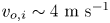 ${v_{o,i}}\sim 4\ \textrm{m}\ {\textrm{s}^{ - 1}}$), where the initial deviation is maximum.
Thus, the linear approximation is valid for  $t > 13\ \textrm{ms}$ for all of the cases in current experiments, where the higher-order terms can be neglected. This is also evident in the plots in figure 9, where the theoretical graph of the non-equilibrium regime is only plotted beyond
 $t > 13\ \textrm{ms}$ (
 $\tau \sim 130$). Thus, the linear proportionality can be established as follows:
 \begin{equation}\frac{{\textrm{d}\delta }}{{\textrm{d}t}}\sim [{\delta _{inst}} - {\delta _{eq}}({v_{rel,inst}})].\end{equation}
As the instantaneous relative velocity can be expressed in terms of time ( $t$), the above equation can be re-written in terms
 ${v_{rel}}$ for convenience. Since, the flame state parameter (
 $\delta $) is linearly related to h/d ((3.38);
 $\delta = p(h/d) + q$) and
 $h/d$ is linearly correlated with
 ${v_{rel}}$ (3.6 and 3.29), the rate of decrease in the instantaneous flame state parameter
 $(\textrm{d}\delta /\textrm{d}t)$ will also be proportional to the extent of deviation of the experimental
 ${v_{rel,inst}}$ from the relative velocity
 ${v_{rel,eq}}({\delta _{inst}})$ that corresponds to the experimental instantaneous flame state
 $({\delta _{inst}})$ at equilibrium.
For t > 0
 \begin{equation}\frac{{\textrm{d}\delta }}{{\textrm{d}t}} = K ({v_{rel,inst}} - {v_{rel,eq}}({\delta _{inst}}))\end{equation}
or
 \begin{equation}\frac{{\textrm{d}\delta }}{{\textrm{d}t}} = K^{\prime}({\tilde{v}_{rel,inst}} - {\tilde{v}_{rel,eq}}({\delta _{inst}}));\quad \textrm{where}~\left( {{{\tilde{v}}_{rel}}\sim \frac{{{v_{rel}}}}{{S_L^o}}} \right),\end{equation}
where K is a proportionality constant. Here,  ${\tilde{v}_{rel}}$ is the relative flow velocity normalized with the laminar flame speed (
 $S_L^o$),
 ${v_{rel,inst}}$ is the actual relative flow velocity and
 ${\delta _{inst}}$ represents the instantaneous flame state based on the flame type and dimensions at a particular instant. Also,
 ${v_{rel,eq}}({\delta _{inst}})$ is the relative flow velocity at which the instantaneous flame state (
 ${\delta _{inst}}$) is supposed to exist in equilibrium conditions. It is to be noted that the right-hand side in (3.42) is negative as
 ${v_{rel,inst}} < {v_{rel,eq}}({\delta _{inst}})$;
 $\delta $ also decreases temporally until equilibrium is reached; hence, the negative sign is not present in (3.42) when compared with (3.39). When equilibrium is reached,
 ${v_{rel,inst}} = {v_{rel,eq}}({\delta _{inst}})$ and
 $\textrm{d}\delta /\textrm{d}t = 0$. This formulation is valid until the equilibrium is reached, after which, even though
 ${\textrm{v}_{rel, inst}}$ increases due to the acceleration of the droplet, the equilibrium condition of
 ${v_{rel,inst}} = {v_{rel,eq}}({\delta _{inst}})$ will be followed as the flame has re-adjusted fully to the surrounding flow and starts to respond coherently to temporal variations of
 ${v_{rel,inst}}$ as imposed by (3.6) or (3.29), depending on the flame type.
3.4. Flame luminosity variation (${I_f}$)

The flame luminosity ( ${I_f}$) measured from the experiments is acquired using a UV transparent lens, without an OH* filter (due to the experimental limitations of low-intensity flame imaging at higher f.p.s.). Hence, the luminosity signal does not directly correspond to the flame heat release rate; however, the OH* chemiluminescence band is a subset of the cumulative signal that the high-speed camera captures. As the flame luminosity data are not obtained in a specific wavelength band, the pixel-wise flame intensity can only be used as supporting and corroborative evidence to support the already established conclusions in the previous sections regarding the variation in flame shape and height. From the previous experiments (Pandey et al.), it has been established that the change in the instantaneous line-of-sight flame area (
 ${A_f}$) will alter the overall flame luminosity signal received by the camera. Thus, the temporal flame luminosity variation will approximately reflect the temporal flame height variation, and a larger flame corresponds to a higher net luminosity signal. Thus, the flame luminosity time series will follow a trend that reflects the droplet height variation established in the previous sections.
For the edge-stabilized wake flame and the bluff-body-stabilized flame, the flame luminosity is observed to vary in coherence with the variation of the h/d ratio temporally. The normalized flame luminosity is plotted against normalized time ( $\tau \sim t/{t_r}$) in figure 7 for different co-flow velocities,
 ${v_{o,i}} = 2.2,3,4\ \textrm{m}\ {\textrm{s}^{ - 1}}$. The time (t) is normalized using the reaction time scale (
 ${t_r}$) calculated using
 ${t_r}\sim \alpha /S_L^2$, which is found to be of the order of
 ${\sim} {10^{ - 4}}\ \textrm{s}$ (
 $\alpha $ is thermal diffusivity and
 ${S_L}$ is flame speed). In figure 7, the non-equilibrium regime is denoted with yellow background, whereas the equilibrated regime is shown using a blue background for all cases. The flame luminosity plots in figure 7 give an overview of different consecutive events discussed so far during the droplet flight time.
Flame luminosity variation normalized using time-averaged luminosity value ( ${I_f}/{I_{avg}}$) for freely falling droplet, plotted against normalized time (
 $\tau \sim t/{t_r}$) with imposed co-flow velocities (a)
 ${v_{o,i}}\sim 2.2\ \textrm{m}\ {\textrm{s}^{ - 1}}$, (b)
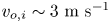 ${v_{o,i}}\sim 3\ \textrm{m}\ {\textrm{s}^{ - 1}}$, (c)
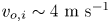 ${v_{o,i}}\sim 4\ \textrm{m}\ {\textrm{s}^{ - 1}}$. Different flame types are denoted by different coloured data points. The initial non-responsive regime, non-equilibrium and equilibrated regimes are shown by green, yellow and blue backgrounds, respectively. The temporal flame luminosity variation reflects the temporal flame height variation. (d) Schematic of flame evolution hypothesized when the value of relative bulk flow velocity experienced by a falling droplet (
 ${v_{rel}}$) increases monotonically with time in the fully equilibrated regime, starting from reverse flame (
 ${v_{rel}} < 0$ means the relative flow with respect to the droplet is downwards). The green dotted lines represent the transition phase, where the flame dynamically evolves through intermediate states while transitioning stabilization to another.

It is to be noted that, in all of the cases, a small rise in flame luminosity is observed during the initial stages of the experimental data. This can be attributed to the non-responsiveness of the droplet flame to the co-flow, where the co-flow velocity is not experienced by the droplet (shown by the green background in figure 7). This effect is observed for all co-flow velocities, as shown in figure 7, and is neglected for simplicity as this occurs for a very short period of time in comparison with the total droplet flight time. The analysis is performed for the period after this initial non-responsive phase for simplicity.
From figure 2, it is observed that, in the case corresponding to  ${v_{o,i}}\sim 2.2\ \textrm{m}\ {\textrm{s}^{ - 1}}$
 $({\tilde{v}_{o,i}}\sim 3.5)$, the height of the initial bluff-body-stabilized flame flattens until 40 ms (
 $\tau \sim 400$), where the equilibrium is reached; then, the flame height starts to increase back as the droplet accelerates. A similar trend is also observed in the flame luminosity time series for
 ${v_{o,i}}\sim 2.2\ \textrm{m}\ {\textrm{s}^{ - 1}}$ (figure 7a).
It is observed from figure 2(b) that, for 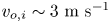 ${v_{o,i}}\sim 3\ \textrm{m}\ {\textrm{s}^{ - 1}}$
 $({\tilde{v}_{o,i}}\sim 4.8)$, the initial open-brush-shaped wake flame flattens and then transitions into an edge-stabilized wake flame, whose flame height reduces temporally in the range
 $t\sim 35\unicode{x2013} 39\ \textrm{ms}$ (
 $\tau \sim 350\unicode{x2013} 390$). A similar trend is reflected in the flame luminosity of the edge-stabilized wake flame after ∼39 ms (
 $\tau \sim 390$), where
 ${I_f}$ starts to increase (shown in grey colour) after its initial decrease (shown in orange colour); see figure 7(b). Beyond this point, the edge-stabilized wake flame starts to come closer to the droplet, tending to envelop it. A fully enveloped flame is a pure diffusion flame, whereas the edge-stabilized wake flame has premixed flame wings propagating upstream, with a diffusion flame zone for fuel-rich conditions. Hence, as the edge-stabilized wake flame tries to envelop the droplet, the flame structure and stabilization are altered from the edge-flame mode to the pure diffusion flame mode. The flame luminosity (
 ${I_f}$) reflects this trend as
 ${I_f}$ continues to increase as the flame envelops the droplet. The highest peak of the flame luminosity plot corresponds to the fully enveloped structure (pure diffusion flame).
For 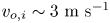 ${v_{o,i}}\sim 3\ \textrm{m}\ {\textrm{s}^{ - 1}}$, the equilibrium is reached when the flame is fully enveloped. It is to be noted that the droplet is continuously accelerating under gravity. Hence, once equilibrium is attained, the value of
 ${v_{rel,inst}}$ experienced by the droplet flame continuously increases with time. This can be observed in figure 2(b), where the enveloped flame transitions into an edge-stabilized wake flame due to forward extinction, and the flame height increases temporally (after
 $\tau \sim 630$, shown in yellow colour). The edge-stabilized wake flame eventually transitions into an open-brush-shaped wake flame (
 $\tau \sim 780$). This is also reflected in the equilibrated regime in figure 7(b), the flame luminosity shows an increasing trend with time for both edge-stabilized and open-brush-shaped wake flame, except during transition.
For 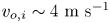 ${v_{o,i}}\sim 4\ \textrm{m}\ {\textrm{s}^{ - 1}}$
 $({\tilde{v}_{o,i}}\sim 6.3)$ as shown in figure 2(c), the flame evolution happens along a similar path as observed in the case with
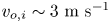 ${v_{o,i}}\sim 3\ \textrm{m}\ {\textrm{s}^{ - 1}}$. However, after enveloping the droplet, the flame transitions into a reverse flame mode around
 $t\sim 31\ \textrm{ms}$ (
 $\tau \sim 310)$. The reverse flame is initially in the reverse edge-stabilized configuration, which later transitions into a reverse open-brush-shaped flame. The flame height is then observed to increase in the reverse open-brush flame until
 $t\sim 55\ \textrm{ms}$ (
 $\tau \sim 550$), where it reaches equilibrium, after which the reverse open-brush flame height decreases, and the flame transitions into a reverse edge-stabilized flame before enveloping the droplet. The reverse edge-stabilized flame height continuously decreases until it starts enveloping the droplet at
 $\tau \sim 960$ (grey colour). Later on, the enveloped flame transitions into an upright edge-stabilized wake flame (yellow colour) and then into an open-brush wake flame (blue colour), with a continuous increase in flame height. The flame luminosity also follows a similar trend to that of the magnitude of flame height, with two large peaks corresponding to the two enveloping events, as shown in figure 7(c). It is to be noted that this increasing trend in flame height and flame luminosity with
 ${v_{rel}}$ is not followed during the transitions between different flame structures. This phenomenon will be discussed in § 3.5.
Figure 7(d) depicts the sequence of flame transition events, flame shapes and stabilization mechanisms, with increasing relative flow velocity from left to right. Since the droplet continuously accelerates due to gravity, the relative flow velocity around such a freely falling droplet should increase monotonically. Hence, the flame response should be in the forward direction of the sequence shown in figure 7(d) (in a fully equilibrated regime). Hence, experimentally, whenever a flame transition is happening in accordance with the increasing relative flow velocity, it is concluded to be in an equilibrated regime, whereas if the flame transition is in the opposite direction, it is concluded to be in a non-equilibrated regime.
3.5. The transition between flame configurations
3.5.1. Transition 1: edge-stabilized wake flame to open-brush wake flame $(20 < R{e_{local}} < 30)$

It is to be noted that the bluff-body wake flame to edge-stabilized flame transition occurs in the non-equilibrium regime. Whereas the reverse, edge-stabilized flame to bluff-body flame, transition occurs after the flame has already achieved equilibrium.
For 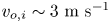 ${v_{o,i}}\sim 3\ \textrm{m}\ {\textrm{s}^{ - 1}}$ case (
 ${\tilde{v}_{o,i}}\sim 4.8$), during edge-stabilized to bluff-body flame transition (equilibrated regime), the edge-stabilized flame height initially starts to increase in response to the increasing instantaneous relative velocity of the flow (
 ${v_{rel,inst}}$) due to gravitational acceleration between 63 and 67 ms (figure 2b). However, between 67 and 79 ms (
 $\tau \sim 670\unicode{x2013} 790$), the flame height starts to decrease until it reaches a minimal value. During this process, the flame transitions into an open-brush shape. This decreasing phase of flame height before transition demonstrates the re-adjustment of the flame from one stabilization mechanism to another. The temporal flame intensity variation plot in figure 8(a) reflects a similar trend as that of the flame height variation for transition 1.
Flame luminosity variation normalized using time-averaged luminosity value ( ${I_f}/{I_{avg}}$) plotted against normalized time (
 $\tau \sim t/{t_r}$) for the corresponding flame images for
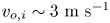 ${v_{o,i}}\sim 3\ \textrm{m}\ {\textrm{s}^{ - 1}}$ during the transition of: (a) transition 1, edge-stabilized wake flame (yellow) to bluff-body-stabilized wake flame (blue),(b) transition 1: backwards, open-brush flame (blue) to edge-stabilized flame (yellow). The transition zone is shown in green colour. (c) Variation of normalized flame luminosity and flame images for
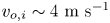 ${v_{o,i}}\sim 4\ \textrm{m}\ {\textrm{s}^{ - 1}}$ during the enveloping event (transition 2: edge-stabilized to envelop) plotted against
 $\tau \sim t/{t_r}$. (d) Equivalence ratio (
 $\boldsymbol{\phi }$) obtained for different flow velocities and the equivalence ratio computed at the pure diffusion limit (
 ${\boldsymbol{\phi }_{\boldsymbol{diff}}}$), all plotted against varying axial flame stand-off distance which is normalized using droplet diameter (x/d).(e) Schematic of the mass diffusion of fuel and air for the pure diffusion flame limit.
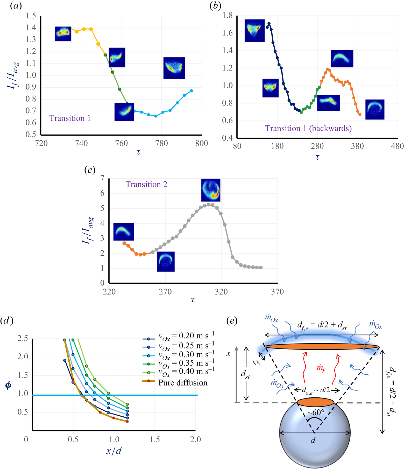
In the case of the reverse transition i.e. bluff-body wake flame to edge-stabilized flame (non-equilibrated regime), a slight increase in the normalized flame height  ${(h/d)}$ is observed between 26 and 34 ms (
 $\tau \sim 260\unicode{x2013} 340$) during which it transitions to an edge flame, and then it starts to decrease further before enveloping (figure 2b). The temporal flame intensity variation plot in figure 8(b) reflects a similar trend to that of the flame height variation for transition 1 in the reverse direction. In both cases, the flame height variation and the flame luminosity variation are in agreement with each other's trends, as the net flame luminosity indirectly depends on the flame dimensions.
In edge-stabilized flame, the flame is stabilized at the flame base, as explained in § 3.2.1, due to the balance between the local flame speed and flow velocity at the droplet. However, once the instantaneous upstream velocity ( ${v_{rel,inst}}$) exceeds the edge-flame speed (
 ${S_E}$), the edge-stabilized flame cannot be stabilized, which may result in a blowoff. Nevertheless, current experiments show that the flame alters its stabilization mechanism to remain stabilized at a higher
 ${v_{rel,inst}}$, in the droplet wake, beyond
 $Re > 30$.
It is known that the flow over a sphere shows an attached flow for  $0 < Re < 20$, the flow detaches with symmetric wake eddies for
 $20 < Re < 130,$ produces slight periodic oscillations for
 $130 < Re < 300$ and shows vortex shedding for
 $Re > 300 $ (Taneda Reference Taneda1956; Goldburg & Florsheim Reference Goldburg and Florsheim1966; Kalra, T.R. Reference Kalra and U1971; Sakamoto & Haniu Reference Sakamoto and Haniu1990). The value of
 $Re$ is calculated for the droplet in the current experiments to check the flow characteristics and the Re range for the edge-stabilized flame is
 $9 < Re < 18$ and
 $29 < Re < 100$ for the bluff-body-stabilized flame configuration. The wake is characterized by an attached flow without eddies (see figure 4b) in the case of the edge-stabilized flame (
 $9 < Re < 18$), and it is expected to have a recirculation zone in the case of the bluff-body-stabilized flame (
 $29 < Re < 100$), see figure 6(a).
Hence, in case of transition 1, when the Reynolds number reaches the critical value  $Re\sim 20\unicode{x2013} 30$, the flow over the droplet detaches from the wake to form recirculating eddies near the rear stagnation zone. This disturbs the attached flow field in the wake, which was responsible for generating the equivalence ratio gradient field necessary for edge stabilization. Thus, due to the formation of the rear stagnation vortical structures for (
 $Re > 30$), the flame shape alters from a dome-shaped edge-stabilized to a bluff-body-stabilized configuration (open-brush-shaped wake flame).
Hence, during transition 1, the edge-flame height suddenly starts to decrease, re-adjusting to flow field at higher Reynolds numbers (see figure 2b) wherein the stabilization mechanism itself is altered to a bluff-body wake stabilization after  $\tau \sim 790$. During the reverse of transition 1, as the open-brush flame transitions back to edge-stabilized flame in the non-equilibrium regime, the stabilization mechanism changes from bluff-body stabilization to edge-flame stabilization as the Reynolds number becomes
 $Re < 20$, which results in an attached flow. Edge-stabilized flame gets established in the absence of rear stagnation vortical structures corresponding to the instantaneous flow velocity (
 ${v_{rel,inst}}$).
3.5.2. Transition 2: edge-stabilized wake flame to enveloped flame $(0 < R{e_{local}} < 5)$

It is known that, as the velocity is reduced, the edge-stabilized flame comes closer to the droplet, forming an enveloped flame. The numerical simulation conducted by Chiu (Reference Chiu2000) has also confirmed that, as Re is reduced, the wake flame transitions into a side flame (partially enveloping), which finally envelops the droplet below a critical Re. It is known that the enveloped flame is a pure diffusion flame  $(R{e_{local}} \to 0)$, whereas the edge-stabilized flame primarily has a premixed flame front (Chen & Lin Reference Chen and Lin2012). Hence, while the edge-stabilized flame is trying to envelop the droplet, the extent of the premixed mode decreases, and the extent of the diffusion mode of mass transfer increases. Finally, when it is fully enveloped, it becomes a pure diffusion flame where fuel diffuses from the inside, and the oxidizer diffuses from the outside. As discussed in § 3.1, for
 ${v_{o,i}}\sim 4\ \textrm{m}\ {\textrm{s}^{ - 1}}$
 $({\tilde{v}_{o,i}}\sim 6.3)$, the edge-stabilized wake flame
 $(5 < R{e_{local}} < 20)$ tries to envelop the droplet around 26 ms (
 $\tau \sim 260$), thus fully transitioning into an enveloped flame around 30 ms (
 $\tau \sim 300$). The similar trend is reflected in the flame luminosity plot, as shown in figure 8(c), where
 ${I_f}$ starts to increase substantially and peaks at 30 ms (
 $\tau \sim 300$) corresponding to the fully enveloped state of the droplet flame. It is to be noted that the flame luminosity is found to be maximum in the fully enveloped state compared with the wake flame configuration.
From the experiments, the relative flow velocity ( ${v_{rel}}$) is found to be in the range of 0.2–0.4 m s−1
 $(0.31 < {\tilde{v}_{o,i}} < 0.64)$, for the edge-stabilized wake flame. Following a similar procedure to § 3.2.1, the equivalence ratio (
 ${\boldsymbol{\phi }_{\boldsymbol{m}}}$) is calculated using (3.7–3.17) for different values of
 ${v_{rel}}$ in the mentioned range for varying values of flame stand-off distance along the normalized axial direction (
 $x/d$) and is plotted in figure 8(d). This shows that the equivalence ratio plot and the axial stoichiometric location (
 ${x_{\boldsymbol{\phi } = {\bf 1}}}$) come closer to the droplet as
 ${v_{rel}}$ decreases. Considering the pure diffusion limit, the axial variation of the equivalence ratio (
 ${\boldsymbol{\phi }_{\boldsymbol{diff}}}$) has to be estimated and then compared with the equivalence ratio corresponding to different
 ${v_{rel}}$ (for the premixed mode).
For the pure diffusion flame case, since the flame tends to envelop the droplet, the schematic depicted in figure 8(e) has been considered. It shows that only fuel and oxidizer diffusion is considered for this case. It is assumed that the flame is partially enveloping the droplet, subtending an angle of  $60^\circ$ at the droplet centre, for simplicity (see figure 8e). The area of the droplet and flame are assumed to be circular, whose diameter is calculated geometrically using the angle subtended. The equivalence ratio for pure diffusion condition (
 ${\boldsymbol{\phi }_{\boldsymbol{diff}}}$) is calculated using (3.17), whose fuel–air ratio is obtained based on the fuel diffusion mass flow rate (
 ${\dot{m}_{F,diff}}$) and oxidizer diffusion mass flow rate (
 ${\dot{m}_{Ox,diff}}$) given by (3.43) (see figure 8e)
 \begin{gather}{\dot{m}_{F,diff}}\sim {\rho _F}\frac{\mathrm{\mathfrak{D}}}{{{d_{st}}}}\frac{{\rm \pi} }{4}d_{o,e}^2,\end{gather}
 \begin{gather}{\dot{m}_{Ox,diff}}\sim {\rho _{Ox}}\frac{\mathrm{\mathfrak{D}}}{{{t_{flame}}}}\left( {\frac{{\rm \pi} }{4}d_{f,e}^2} \right) + {\rho _{Ox}}\frac{\mathrm{\mathfrak{D}}}{{{d_{o,e}}/2}}{\rm \pi} \frac{{{d_{o,e}} + {d_{f,e}}}}{2}{d_{st}},\end{gather}
where  ${t_{flame}}$ is the length scale corresponding to flame thickness (Vancoillie et al. Reference Vancoillie, Demuynck, Galle, Verhelst and van Oijen2012), and
 $\mathrm{\mathfrak{D}}$ is the mass diffusion coefficient. Since the fuel has to travel the stand-off distance (
 ${d_{st}}$) to reach the flame,
 ${d_{st}}$ is used as the length scale, whereas the oxidizer is freely available all around the flame, so the oxidizer just has to diffuse through a length scale comparable to the flame thickness (
 ${t_{flame}}$).
Figure 8(d) shows that the axial variation of the equivalence ratio corresponding to the diffusion limit ( ${\boldsymbol{\phi }_{\boldsymbol{diff}}}$) and the
 ${\boldsymbol{\phi }_{\boldsymbol{m}}}$ variation for
 ${v_{out}} \sim 0.2\ \textrm{m}\ {\textrm{s}^{ - 1}}$ (
 ${\boldsymbol{\phi }_{{v_{out}} = 0.2\ \textrm{m}\ {\textrm{s}^{ - 1}}}}$), both match near the stoichiometric conditions, i.e.
 ${\boldsymbol{\phi }_{{v_{out}} = 0.2\ \textrm{m}\ {\textrm{s}^{ - 1}}}} \approx {\boldsymbol{\phi }_{\boldsymbol{diff}}}$, where the flame gets stabilized. As it is hypothesized that, while the edge-stabilized flame transitions to an enveloped flame, the premixed flame front gradually diminishes, leaving behind the diffusion flame alone. The variations of the equivalence ratio for the two cases matching with each other, i.e.
 ${\boldsymbol{\phi }_{{v_{out}} = 0.2\ \textrm{m}\ {\textrm{s}^{ - 1}}}} \approx {\boldsymbol{\phi }_{\boldsymbol{diff}}}$, suggests that the velocity scale corresponding to the case of
 ${v_{out}} = 0.2\ \textrm{m}\ {\textrm{s}^{ - 1}}$ is of the same order as that of the pure diffusion limit (
 ${v_{NC}}\sim 0.2\ \textrm{m}\ {\textrm{s}^{ - 1}}$). This is conjectured to be the transition condition between edge-stabilized flame and enveloped flame. Figure 8(d) shows that the transition between the edge-stabilized and diffusion flames approximately occurs at
 ${v_{out}} = 0.2\ \textrm{m}\ {\textrm{s}^{ - 1}}$. To verify this conclusion, the average value of
 $h/d$ ratio for the edge-stabilized wake flame corresponding to the beginning of the enveloping event (
 $\tau \sim 260$; figure 8c) is extracted from the experimental data
 $(h/{d_{before~envelop}} \le 0.45)$. When this value is substituted into the
 ${v_{rel}}~\&~h/d$ relation for the edge-stabilized flame (3.6), the value of
 ${v_{rel}}$ is obtained to be
 ${v_{rel,h/d = 0.45}} = 0.188\ \textrm{m}\ {\textrm{s}^{ - 1}}$
 $({\tilde{v}_{rel,h/d = 0.45}}\sim 0.3)$. This value is in very close agreement with the
 ${v_{rel}}\sim 0.2\ \textrm{m}\ {\textrm{s}^{ - 1}}$
 $({\tilde{v}_{rel}}\sim 0.31)$ value obtained using the equivalence ratio method.
3.6. Mathematical formulation to estimate the temporal evolution of flame shape
From figures 2 and 7, it is evident that the flame evolution and luminosity variation are captured by the variation in the flame height (h). Hence, the normalized flame height  $(h/d)$ will be from hereon used to describe the state of a particular type of flame. As shown in figure 6(d), the relative flow velocity experienced by the droplet (
 ${v_{rel}}$) increases monotonically with time due to the acceleration of the droplet until the droplet exits the central co-flow tube and encounters the co-flow velocity (
 ${v_{o,i}}$) at z = 0+. The instantaneous droplet velocity is
 ${u_o}$ and initial droplet velocity when the droplet exits the co-flow central coflow at z = 0+ is
 ${u_{o,i}}$. At z = 0,
 ${v_{rel}}$ value undergoes a sudden jump from
 ${v_{rel}}\sim {u_{o,i}}$ to
 ${v_{rel}}\sim {u_o} - {v_o}$ at z = 0+, after which
 ${v_{rel}}$ again continues to increase monotonically due to gravity (see figure 6d). For the theoretical formulation, the time when the droplet flame encounters the co-flow at z = 0 is considered to be
 $t = 0$ for simplicity. Practically, at z = 0, the droplet flame does not fully experience the co-flow velocity (
 ${v_o}$) immediately, as the velocity has to diffuse from outside towards the droplet flame (initial non-responsive regime). However, for simplicity, it is assumed that the droplet flame encounters the co-flow velocity (
 ${v_o}$) immediately for the sake of theoretical analysis. This will lead to a slight deviation in the theoretical estimation of the evolution of
 $h/d$ from the actual experimentally measured value during the initial stages at
 $z \to 0$.
Considering the mathematical formulation (3.42) obtained from the spring–mass system analogy for the non-equilibrium regime (§ 3.3), rewritten below.
For t > 0
 \begin{equation}\frac{{\textrm{d}\delta }}{{\textrm{d}t}} = K^{\prime} ({\tilde{v}_{rel,inst}} - {\tilde{v}_{rel,eq}}({\delta _{inst}})). \end{equation}
Here,  $\delta $ is the flame state parameter which is used to signify the flame state based on the flame shape descriptors as mentioned in (3.38) and
 ${\tilde{v}_{rel}}$ is the relative flow velocity normalized with
 $S_v^o$. Also,
 ${v_{rel,inst}}$ is the instantaneous flow velocity experienced by the droplet flame at any given time;
 ${v_{rel,inst}}$, as shown in figure 6(d), evolves with time due to the droplet acceleration under gravity. Considering negligible droplet regression in the scope of the experimental investigation, as explained in § 3.1,
 ${v_{rel,inst}}$ can be theoretically obtained as follows:
 \begin{equation}{v_{rel,inst}} = {u_{o,i}} - {v_{o,i}} + gt,\end{equation}
where  ${u_{o,i}}$ is the initial droplet velocity at the co-flow exit,
 ${v_{o,i}}$ is the co-flow velocity and g is the acceleration due to gravity. It is to be noted that, in (3.45), the instantaneous co-flow velocity (
 ${v_o}$) is considered to be equal to the initial value (
 ${v_{o,i}}$) during the non-equilibrium regime, for simplicity. This is because for all the cases, during the non-equilibrium regime (t < 0.06 s), the co-flow velocity does not deviate more than
 $10\ \textrm{\%}$ (see figure 6d), and the assumption
 ${({v_o})_{non\textrm{ - }equilibrium}}\sim {v_{o,i}}$ is reasonable.
The parameter  ${v_{rel,eq}}({\delta _{inst}})$ is the relative flow velocity corresponding to the instantaneous flame state parameter
 ${\delta _{inst}}$ and is calculated from (3.46), which is a linear relationship between
 ${v_{rel}}$ and
 $\delta $ that can be obtained from the linear equations in (3.6), (3.29) and (3.38)
 ${\delta _{inst}} = p(h/{d_{inst}}) + q$
 \begin{gather}{v_{rel,EdgeStb}}(\delta ) = {k_v}{\delta _{EdgeStb}};\quad \textrm{for edge-stabilized wake}\ \textrm{flame,}\end{gather}
 \begin{gather}{v_{rel,bluffbody}}(\delta ) = {k_b}{\delta _{bluffbody}};\quad \textrm{for bluff-body-stabilized}\ \textrm{wake}\ \textrm{flame,}\end{gather}
where  ${k_v} $,
 ${k_b}$ are constants. Substituting (3.45) in (3.42) gives
 \begin{equation}\frac{{\textrm{d}\delta }}{{\textrm{d}t}} = K^{\prime} \left( {\frac{{{u_o} - {v_{o,i}} + gt - {v_{rel,eq}}({\delta_{inst}})}}{{S_L^o}}} \right).\end{equation}
Rewriting the above equation in terms of  ${v_{rel}}$ instead of the normalized value i.e.
 ${\tilde{v}_{rel}}$, for simplicity (3.42)
 \begin{equation}\frac{{\textrm{d}\delta }}{{\textrm{d}t}} = K({u_o} - {v_{o,i}} + gt - {v_{rel,eq}}({\delta _{inst}})).\end{equation}
Substituting the corresponding values of  ${v_{rel,eq}}({\delta _{inst}})$ from (3.46), in the above equation
 \begin{gather}\frac{{\textrm{d}{\delta _{EdgeStb}}}}{{\textrm{d}t}} + K{k_v}{\delta _{EdgeStb}} = K({u_o} - {v_{o,i}} + gt),\end{gather}
 \begin{gather}\frac{{\textrm{d}{\delta _{Bluffbody}}}}{{\textrm{d}t}} + K{k_b}{\delta _{Bluffbody}} = K({u_o} - {v_{o,i}} + gt).\end{gather}
The two ordinary differential equations (3.49) and (3.50) are obtained after rearranging the terms with  $\delta $ as the dependent variable and t as the independent variable. The ordinary differential equations are then solved using the integrating factor method, and the solutions for
 $\delta $ for different flame types are obtained as follows:
 \begin{gather}{\delta _{EdgeStb}} = \frac{{{u_o} - {v_{o,i}} + gt}}{{{k_v}}} - \frac{{gt}}{{Kk_v^2}} + \frac{g}{{{K^2}k_v^3}} - Kc\,{\textrm{e}^{ - K\,{k_v}t}},\end{gather}
 \begin{gather}{\delta _{bluffbody}} = \frac{{{u_o} - {v_{o,i}} + gt}}{{{k_b}}} - \frac{{gt}}{{Kk_b^2}} + \frac{g}{{{K^2}k_b^3}} - Kc\,{\textrm{e}^{ - K\,{k_b}t}},\end{gather}
where c is the integration constant. This formulation is valid as long as  $\textrm{d}\delta /\textrm{d}t \le 0$, i.e. until equilibrium is reached. Once the equilibrium is reached (
 ${v_{rel,inst}} = {v_{rel,eq}}({\delta _{inst}})$),
 $\delta $ or
 $h/d$ varies only based on the evolution (3.45) of the instantaneous relative flow velocity (
 ${v_{rel,inst}}$) due to droplet acceleration (based on (3.6) and (3.29)). Equations (3.51) and (3.52) are converted in terms of
 $h/d$ using (3.38), (3.46), (3.6) and (3.29).
It is to be noted that the negative value of  $h/d$ suggests that it is a reverse flame. That means,
 $h/{d_{EdgeStb}} < 0$ suggests that the flame is reverse edge-stabilized flame and
 $h/{d_{bluffbody}} < 0$ suggests the flame is a reverse bluff-body open-brush flame.
From the experimental data (see figure 2), the range of  $h/d$ values is obtained for different flame types observed experimentally, such as edge-stabilized wake flame:
 $0.35 < h/d < 0.8$ (corresponding to
 $5 < R{e_{local}} < 20$); bluff-body-stabilized open-brush flame:
 $h/d > 0.4$ (corresponding to
 $R{e_{local}} > 20$); reverse edge-stabilized flame:
 $- 0.35 < h/d < - 0.8$ (
 $5 < R{e_{local}} < 20$); and reverse open-brush flame:
 $h/d < - 0.4$ (
 $R{e_{local}} > 20$).
It is to be noted that the  $h/d$ value cannot be calculated for the enveloped flame or during the enveloping phase. Hence, for the formulation purpose, the flame is considered to correspond to an enveloped flame when the
 $h/d$ value for the branched-edge flame becomes zero. This assumption is justified because, in the range of
 $- 0.2 < h/d < 0.2$ obtained from (3.51), the corresponding experimental flame images show the transition of edge-stabilized wake flame into fully enveloped flame.
Thus, for the non-equilibrium regime  $(\textrm{d}\delta /\textrm{d}t \le 0)$, the
 $h/d$ values are obtained using (3.51) and (3.52) for the corresponding ranges, using (3.6), (3.29), and (3.46), as shown below
 \begin{align}\left(\dfrac{h}{{{d}}}\right)_{EdgeStb} & = \dfrac{1}{{0.28}} \left[ {{u_o} - {v_{o,i}} + gt - \dfrac{{gt}}{{K{k_v} }} + \dfrac{g}{{{K^2}k_v^2}} - K{k_v}c\,{\textrm{e}^{ - K{k_v}t}} - 0.06} \right];\nonumber\\ & \quad \left\{ {0.35 < \dfrac{h}{d} < 0.8~\& - 0.35 < \dfrac{h}{d} < - 0.8} \right\},\end{align}
 \begin{align}\left(\dfrac{h}{{{d}}}\right)_{BB} & = \dfrac{1}{{1.4}} \left[ {{u_o} - {v_{o,i}} + gt - \dfrac{{gt}}{{K{k_b} }} + \dfrac{g}{{{K^2}k_b^2}} - K{k_b}c\,{\textrm{e}^{ - K{k_b}t}} - 0.1} \right];\nonumber\\ & \quad \left\{ {\dfrac{h}{d} > 0.4~\&~\dfrac{h}{d} < - 0.4} \right\}.\end{align}
For the equilibrium regime, since the axial distance from the co-flow tube exit  $z \gg 1$, the variation of the co-flow velocity (
 ${v_o}$) with axial distance (see figure 6d) is considered in calculating the instantaneous relative flow velocity experienced by the droplet flame given by
 \begin{equation}{v_{rel,inst}} = {u_o} - {\textrm{v}_o} + gt.\end{equation}
The variation of  ${v_o}$ of the co-flow is obtained using the axial variation of the mean velocity of a jet using (3.55). The ratio of mean velocities at two different axial lengths (z) is considered:
 $z = {z_o}$ and
 $z = {z_1}$, where for an axial distance
 ${z_o} \to {0^ + }$, co-flow velocity is assumed to be equal to the initial value (
 ${v_o}\sim {v_{o,i}}$). Here,
 $z = {z_1}$ is the desired axial distance where the velocity needs to be calculated. The value of
 ${v_o}$ at a given axial distance (
 $z = {z_1}$) is calculated based on the droplet location at the given time t, which is computed based on the equation of motion
 $[{z_1} = {z_{droplet}} = {u_o}t + {\textstyle{1 \over 2}}g{t^2}]$
 \begin{gather}\frac{{{v_o}}}{{{v_{o,i}}}} = {\left( {\frac{{z/{D_o}}}{{{v_o}{D_o}/\vartheta }}} \right)^{ - 1/3}},\end{gather}
 \begin{gather}\frac{{{v_o}(z = {z_o})}}{{{v_o}(z = {z_1})}} = {\left( {\frac{{{z_o}}}{z}} \right)^{ - 1/3}}.\end{gather}
Where  ${D_o}$ is co-flow jet width length scale at
 $z = {z_o}$. The
 $h/d$ value for equilibrium regime can be calculated by substituting (3.54), (3.55) in (3.6) and (3.29). The (3.6) and (3.29) are rewritten as (3.56) along with the range of
 $h/d$ values for the corresponding flame regime
 \begin{gather}{v_{rel,EdgeStb}} = 0.28\frac{h}{d} + 0.06;\quad \left\{ {0.35 < \frac{h}{d} < 0.8~\& - 0.35 < \frac{h}{d} < - 0.8} \right\},\end{gather}
 \begin{gather}{v_{rel,bluffbody}} = 1.4 \frac{h}{d} + 0.1;\quad \left\{ {\frac{h}{d} > 0.4~\&~\frac{h}{d} < - 0.4} \right\}.\end{gather}
Thus, the temporal variation of the flame is denoted by the flame shape descriptor  $(h/d)$ is plotted in figure 9 using the equations in (3.53) for the non-equilibrium regime
 $(\textrm{d}\delta /\textrm{d}t \le 0)$, and using (3.54), (3.55) and (3.56) for the equilibrated regime. The temporal variation of the flame shape descriptor
 $(h/d)$ is plotted in figure 9(a–c), for the co-flow velocities
 ${v_{o,i}}\sim 2.2\ \textrm{m}\ {\textrm{s}^{ - 1}}({\tilde{v}_{o,i}}\sim 3.5)$,
 ${v_{o,i }}\sim 3\ \textrm{m}\ {\textrm{s}^{ - 1}}({\tilde{v}_{o,i}}\sim 4.8)$ and
 ${v_{o,i}}\sim 4\ \textrm{m}\ {\textrm{s}^{ - 1}}({\tilde{v}_{o,i}}\sim 6.3)$, respectively. The corresponding experimental values of the flame shape descriptor
 $(h/d)$ are also plotted in figure 9(a–c).
The temporal variations of the flame shape descriptor  $(h/d)$ are plotted for the co-flow velocities (a)
 ${v_{o,i}}\sim 2.2\ \textrm{m}\ {\textrm{s}^{ - 1}}$ (
 ${\tilde{v}_{o,i}}\sim 3.5$), (b)
 ${v_{o,i}} \sim 3\ \textrm{m}\ {\textrm{s}^{ - 1}}$* (
 ${\tilde{v}_{o,i}}\sim 4.8$); the transition between open-brush-shape (bluff-body-stabilized) and edge-stabilized wake flames is represented using green data points, (c)
 ${v_{o,i}}\sim 4\ \textrm{m}\ {\textrm{s}^{ - 1}}$ (
 ${\tilde{v}_{o,i}}\sim 6.3$) respectively – mathematical formulation vs experimental. Continuous lines represent the empirical relation based on classical theories and the individual data points plotted are the experimental values. All the error bars represent an uncertainty of ±10 %. The yellow background represents non-equilibrium regime and blue background represents the equilibrated regime.

In the equilibrated regime, the value of  ${v_{rel,EdgeStb}}$ before the transition (calculated using (3.56)) is in a similar range to the value of
 ${v_{rel,bluffbody}}$ (calculated using (3.56)) corresponding to the
 $h/d$ value after transitioning into an open-brush bluff-body-stabilized flame. This means both the equations in (3.56), which are obtained separately from completely different experimental datasets, are consistent and are in agreement with the temporal evolution of
 $h/d$ and the flame structure, which are observed during the transition in the current experiments.
Figure 9 shows the temporal variation of  $h/d$ for different co-flow velocities, which shows that both mathematically obtained empirical correlation and experimental values are in good agreement with each other. The blue colour data points represent the experimental
 $h/d$ values, and the continuous blue line represent the mathematically obtained correlation of
 $h/d$ for the open-brush-shaped bluff-body wake flame. The orange colour data points represent the experimental
 $h/d$ values, whereas the continuous orange line and yellow line represent the mathematically obtained values of
 $h/d$ for the non-equilibrium and equilibrated regimes, in the case of an edge-stabilized wake flame. The
 $h/d = 0$ data points plotted are just to indicate the occurrence of a fully enveloped flame, which is in good agreement with the prediction from the formulation. The deviation observed between the predicted and experimental values at higher co-flow velocities (
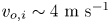 ${v_{o,i}}\sim 4\ \textrm{m}\ {\textrm{s}^{ - 1}}$) is due to the undesirable eddies generated due to turbulent effects. Nevertheless, all the transitions in both the equilibrium and non-equilibrium regimes, and the temporal flame evolutions, are captured with good accuracy by the estimated predictions for all the cases, as shown in figure 9.
4. Conclusion
The current work investigates the evolution of a moving droplet flame when it encounters an abrupt jump in the velocity field, with a comprehensive analysis of local flame stabilization and the mechanisms involved during flame transitions. This study consolidates the different flame structures, flame shapes and their transitions observed in our previous studies. The dynamic flame shape evolution due to variation in the surrounding velocity has been theoretically obtained for different flame structures like the wake-stabilized (edge-stabilized/bluff-body) and fully enveloped configurations. The data from our previous studies have been used as a reference to characterize the flame shape to obtain empirical equations that correlate the relative velocity with the flame shape. When the falling droplet encounters the co-flow, due to the velocity jump, the flame which had been established for the instantaneous droplet velocity prior to the interaction is no longer in equilibrium with the flow. Hence, the flame has to re-adjust to this new velocity until it reaches equilibrium, after which it starts to respond to the relative flow variation coherently. Depending on the instantaneous velocity established using the co-flow, the flame is observed to undergo transitions between different wake flame configurations (both in the upright and reverse directions) or with an enveloped state. The transition mechanisms are explained based on the flame stabilization mechanisms and the flow conditions around the droplet. All the transitions and the evolution of the observed flame shapes have been predicted with reasonable accuracy.
Supplementary material and movies
Supplementary material and movies are available at https://doi.org/10.1017/jfm.2023.949.
Acknowledgements
The authors are thankful to SERB (Science and Engineering Research Board) - CRG: CRG/2020/000055 for financial support.
Declaration of interests
The authors report no conflicts of interest.



