I. INTRODUCTION
Nickel based alloy also known as a group of superalloys, is widely used for various parts of components and structures for aerospace, marine, and automobile industries, as well as chemical processing etc. Specific properties such as high resistance to creep, high toughness, and strength at elevated temperature, good resistance to chemical degradation, and wear have made this alloy well suited for service in extreme environments, especially for high temperature application. However, its low thermal conductivity and specific heat volume leads to high cutting temperature and its superior mechanical properties have also resulted in high cutting force. In addition, chips are easy to stick at the tool tip and tend to generate build up edge (BUE), which results in a rapid tool wear.Reference Liao, Lin and Wang1 Thus, nickel based alloy normally refers to a ‘difficult-to-cut’ material in a machining context.Reference Ezugwu, Bonney and Yamane2
In the case of milling process, it is also known as an interrupted cutting process, where the direction of the cutting force changes due to the tool rotation, and as the tooth enters and leaves the workpiece for every cutting pass.Reference Bayly, Insperger, Mann and Ste3,Reference Kasim, Che Haron, Ghani, Sulaiman and Yazid4 This resulted in various wear mechanisms, cutting temperature, and dynamic stability compared to the continuous cutting process. It is claimed that in cutting superalloy materials, the low thermal conductivity, combined with a high chemical reactivity and adhesion with tool materialsReference Arrazola, Garay, Iriarte, Armendia, Marya and Maître5 means that temperature at the tool tip area rapidly increases, and drastically affects tool wear.Reference Abele, Pfeiffer and Schäfer6,Reference Ribeiro, Moreira and Ferreira7 Thus, an effective high speed cutting application for these types of alloys cannot be optimized due to the extremely high thermal loads applied on the tool material. Based on this issue, most of the superalloy material still being machined under flooding conditions is limited in terms of decreasing high cutting temperatures, increasing tool life, and reducing machining costs while improving environmental sustainability.
The performance of the cutting tool is normally regarded in terms of tool wear and tool life, while the quality of machining performance normally refers to the surface integrity of the machined surface. In this context, it is very important to understand the tribological action of the cutting tool during machining process.
This paper presents the tribology phenomenon in terms of tool wear, cutting force, cutting temperature, and surface integrity of the carbide cutting tool in milling Inconel 718 alloy.
II. EXPERIMENTAL PROCEDURE
The dry cutting process was conducted using a CNC milling machining (DMC 635 V eco, DMG Shanghai MT Co. Ltd., Shanghai, China), which has maximum speed of 8000 RPM. The workpiece material used was the aged-hardened and solution-treated Inconel 718 alloy with a dimension of 150 × 100 × 50 mm rectangular block. The hardness of the prepared workpiece is 42 ± 2 HRC and the chemical composition of Inconel 718 is shown in Table I.
Nominal chemical composition of Inconel 718.

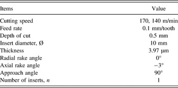
The cutting tool used in the machining test was a Sumitomo ball nose type milling cutter with a nominal diameter of 16 mm attached to a BIG Hi-Power Milling Chuck DV40-HMC20-85 (Sumitomo Electric Industries, Ltd., Itami, Hyogo, Japan) for powerful and precise clamping, and the overhang length was 60 mm. The insert was tungsten carbide with multi-layer PVD TiAlN/AlCrN grade ACK 300. For this experiment, the use of cutting parameters, a cutting tool, and tool holder specification are shown in Table II. The experiment was conducted with sharp cutting edges and all data were measured at the beginning of the cut.
Cutting parameters and cutting tool geometry.

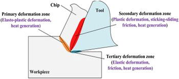
Figure 1 shows the schematic diagram of heat source during the cutting that will affect the quality of machined parts.
Schematic diagram of heat source during cutting.

The workpiece was clamped on the dynamometer and mounted on the table of a CNC vertical machining center. The dynamometer measured the force signals in the three following directions: tangential/cutting force (F x), radial force (F y), and axial force (F z). These three signals of force were then connected to the charge amplifier. The output of dynamic cutting force signals was real-time, captured and stored by Neo-MoMac software.
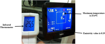
Cutting temperature in deg-C (°C) was measured using infrared thermal imagery, where the temperature was determined by the amount of infrared energy emitted by the object and its emissivity. In this case, the emissivity of Inconel was set to 0.19 according to Cole-Parmer.8 The verification of the emissivity was completed by comparing the temperature from an infrared thermography camera with infrared thermometer (Fig. 2). The measurement was taken within 1 meter as per suggestion of the instrument procedure. The reading was almost same, showing that the emissivity rate was correct. The range of the temperature measured was between −40 and 1500 °C. During the experiment, the highest temperature was taken for every cutting pass.
Verification by comparing the emissivity value of 0.19 with infra-red thermometer.

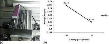
Surface roughness (R a) was measured using a Mitutoyo Surf Test. The measurement of the surface roughness was repeated three times for each run and the average values of these three measurements were taken into consideration to make further analysis.
III. RESULT AND DISCUSSION
A. Cutting temperature and wear
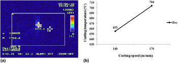
High temperature is generated in milling Inconel 718. As shown in Fig. 3, cutting temperature increases with cutting speed. This finding is similarly obtained by previous researches.Reference Liao, Lin and Wang1,Reference Ueda, Hosokawa, Oda and Yamada9,Reference Ng, Lee, Sharman, Dewes, Aspinwall and Vigneau10 Figure 3(a) shows the gradient temperature of the cutting tool near the vicinity of the depth of cut (DOC) line captured during the milling process at 170 m/min, which corresponds to the highest contact zone and friction interfaced. Figure 3(b) shows the plot of measured cutting temperature versus cutting speed, respectively.
(a) Temperature captured during the milling process at 170 m/min, (b) cutting temperature versus cutting speed.

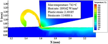
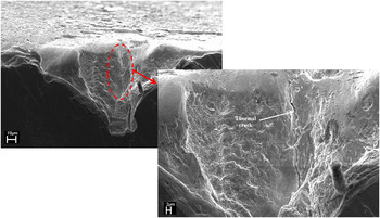
A thermal numerical simulation was performed using Third Wave Advantedge software to ascertain the experimental results obtained. Figure 4 shows the simulation of isothermal contours of temperature distribution for dry condition at the machined surface. In these finite element analyses, the flank face friction has been neglected for a fresh tool cutting edge. The friction can be easily added for future investigation. The highest cutting temperature always occurs at the middle of tool-chip contact area. In this case, the maximum heat generated by the software was 743 °C, close to the result of the experimental value of 704 °C. Since the tool wear depends largely on the temperature generated, the experimental value proved that this location encountered the most severe flank wear along the cutting edge. As the recorded temperature was 704 °C, the cutting tool reached a critical point of temperature for Inconel 718, which is 650 °C. At this point the material hardened as the temperature increased.Reference Liao, Lin and Wang1 According to Katsuhiko et al.,Reference Katsuhiko, Yasuo and Norihiko11 thermal wear in machining Inconel 718 will occur above 680 °C. Figure 5 verified this statement and the thermal crack on cutting tool edge was observed during the machining of Inconel 718.
Dry machining results with modeling of temperature distribution at cutting speed of 170 m/min, feed rate of 0.1 mm/tooth, and depth of cut 0.5 mm.

Thermal crack observed at localized wear on the cutting edge.

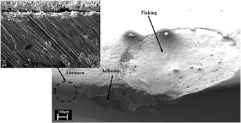
At this high temperature, tool-chip interface was believed to be the main cause of wear, as shown in Fig. 6. Flaking on the rake face caused the coating material to peel off from the substrate and was believed to be the main reason that the cutting edge weakened, causing the end of the tool life. Previous findingsReference Kasim, Che Haron, Ghani, Sulaiman and Yazid4,Reference Katsuhiko, Yasuo and Norihiko11 found that this phenomenon was due to the high temperature generated and cyclic loading lead to a weakened cutting edge.
Abrasion and adhesion at the flank face and flaking on the rake face was among the tool wear observed during milling Inconel 718.

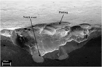
On the other hand, notching was seen on the flank face as shown in Fig. 7. Notching, also known as sliding wear, involved both abrasion and metal transfer, and was greatly influenced by the chemical reactions of the surrounding atmosphere.Reference Trent and Wright12 Besides that, notching is also caused by adhesion between the tool and the chip, with subsequent pull-out of the tool material.Reference Lee, Horne, Tabor, Ludema, Glaeser and Rhee13,Reference Cedergren, Olovsjö, Sjöberg and Nyborg14 It is possible for this incident to occur at high temperature. Zhu et al.Reference Zhu, Zhang and Ding15 stated in previous research that local high temperatures are a key factor affecting tool wear rate, while the impact of cutting force will be relatively weakened. An investigation by Li et al.Reference Li, He, Wang and Wang16 found that welding and adhesion of the worked material onto the cutting tool were the predominant factor(s) that caused severe notching, and so affected the tool rake face from subsequent pull-out of coating and tool substrate. As for this research, it was found that both adhesion and abrasion have given a contribution to the formation of notching.
Notching observed at DOC line where grooving was enlarged due to cyclic load during milling process.

B. Tool wear and surface roughness
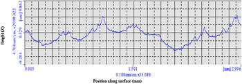
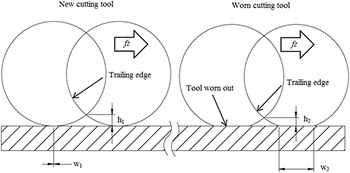
Figure 8(a) shows the roughness measurement and Fig. 8(b) shows the average surface roughness (R a) of the workpiece during the dry cutting process. Due to reduce adhesion at the beginning of cut, low R a values were measured. The surface profilometer pattern of the machined surface is shown in Fig. 9. In addition, Fig. 8(b) also shows that low R a value was obtained at a higher cutting speed compared to lower cutting speed. This was due to an increase in temperature at the higher cutting speed correlated with an increase in residual strain.Reference Arunachalam, Mannan and Spowage17 At high cutting temperature, the cutting tool material became soft. This accelerated as the wear continued, due to its decreased ability to withstand penetration of abrasive particles. At this point, the cutting tool encountered a flank wear formation.Reference Wanigarathne, Kardekar, Dillon, Poulachon and Jawahir18,Reference Kitagawa, Kubo and Maekawa19 The effect of flank wear lowered the trailing edge of the cutting tool and caused the wear scar, which tends to be away from the trailing edge when cutting with this worn insert.Reference Sharman, Hughes and Ridgway20 Due to the wear on the flank surface of the cutting tool becoming wider, it acted as a “wiper” and removed the peaks of the feed mark on the machined surface, directly improving the surface roughness. This is shown in Fig. 10 where a change in segment height (h 2 < h 1) and surface area of the cutting tool is shown when the device is in a state of wear (w 2 > w 1).
(a) Surface roughness measurement, (b) average surface roughness during dry cutting process.

Surface profilometer for dry machining at 170 m/min.

Flank wear effect on machined surface.Reference Kasim21

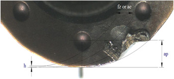
High cutting speed applied in this study proved that a smoother machined surface is obtained and is comparable with manual grinding.Reference Umbrello22 Furthermore, as the machining continued, the R a measured was also acceptable, even though the notching had already been observed on the cutting edge. This is due to the fact that notching does not affect the R a measured, as shown schematically in Fig. 11. When notch wear occurred at the DOC line, flank profile is formed on the machined surface. However, the defect surface was eliminated with the new cut and the defect caused by the flank was not seen. This was due to location of the flank wear area being far from the maximum height of the un-machined surface, h.Reference Grzesik23 The effect of ball tool geometry, called scallop, was not machined due to interval movement of the cutting tool. The scallop height depended on the feed rateReference Feng and Su24 and width of cut,Reference Chen, Huang and Chen25 whichever was the lowest. Low feed rate and small width of cut reduced the scallop height.
Schematic diagram showing that the notch wear did not affect the surface roughness.Reference Kasim21

C. Effect of tool wear and cutting force on microstructure changes
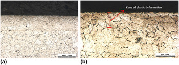
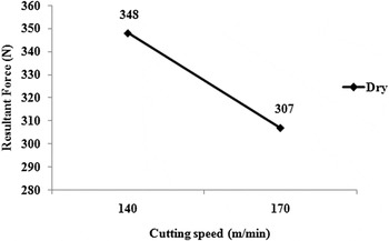
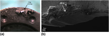
The microstructure near the machined surface is shown in Fig. 12 under 20× magnification and 50× magnification. The grain boundaries observed near the machined surface showed a clearly visible plastic deformation during the vertical milling process. This might be due to the fact that more plastic deformation occurred on the machined surface during dry machining, caused by stronger adhesion of the workpiece material to the cutting tool at higher temperature.Reference Tonshoff and Winkler26 In other words, high cutting temperature together with cutting force acting on the machined surface leads to the deformation of grain structure.Reference Zhou, Bushlya and Stahl27Figure 13 shows the results of resultant cutting force acting on the workpiece during machining process. It is clearly shown that resultant cutting force is decreasing when the cutting speed is increasing. This result is in line with the study done by HasanReference Hasan28 during machining AA2014 (T4) alloy. This is due to low friction forces on the tool rake face at high cutting speed and also low shear forces required to produce the stress for deformation when shear angle increase at high cutting speed. Furthermore, Fig. 14(a) shows chip sticking during dry machining that tends to create BUE [Fig. 14(b)], where BUE generated more friction during machining. This high friction during machining increased the heat generated and plastic deformation. This usually alters the microstructure beneath the machined surface of the alloy and induced residual stress. Similar results were obtained by Aramcharoen and ChuanReference Aramcharoen and Chuan29 when they compared the microstructure change beneath the machined surface under a dry, conventional, and cryogenic cutting process.
Microstructure of machined surface under different conditions and magnification: (a) dry machining (20×), (b) dry machining (50×).

Resultant cutting force during dry condition at different cutting speed.

(a) Chip sticking on the cutting edge, (b) BUE formation.

IV. CONCLUSIONS
This paper focused on the tribological behavior of high speed machining of Inconel 718 alloy at the cutting zone during dry ball nose milling process using a carbide cutting tool. In general, the tribological process of dry machining caused a temperature rise at the tool–chip interface. The cutting speed played an important role; high values of cutting speed increased cutting temperature and resulted in severe tool wear. The main wear mechanism during cutting Inconel 718 were adhesion and abrasion that created notch wear, located near the DOC line. Flaking occurred on the rake face because of the thermal load at that position. It is possible for the combination of notch wear and flaking to cause the cutting tool edge to fail abruptly. Likewise, in this experiment, the cutting tool experienced a thermal crack because the maximum cutting temperature, which is 704 °C, exhibited a critical temperature point of thermal wear for machining Inconel 718.
Another important point to be underlined is that the surface roughness is significantly improved when machining at higher cutting speed ranging between 140 and 170 m/min. This improvement was related to higher temperatures generated at a higher cutting speed, leading to flank wear formation. As the cutting tool became worn, lower surface roughness occurred due to the location of the wear scar, which tended to be away from the trailing edge. Then, the unworn trailing edge acted as a wiper to remove the feed peaks. On the other hand, it was proved that notch wear was not affected by the surface roughness. This study also found that surface roughness in milling Inconel 718 alloy is comparable with those obtained by finishing processes (e.g., manual grinding) when coated carbide tool is used.
In particular, the tribological process of dry milling showed that plastic deformation occurred on the machined surface due to stronger adhesion of the workpiece material when the cutting tool was at a higher temperature. High friction caused by BUE formation increased the heat generated, as well as plastic deformation, which usually alters the microstructure beneath the machined surface.
ACKNOWLEDGMENTS
The machine shop and laboratory facilities at Faculty of Engineering and Built Environment of Universiti Kebangsaan Malaysia are gratefully acknowledged.