1 Introduction
Hydrodynamic turbulence refers to the state of flow in which eddies self-stretch one another, generating a continuous spectrum of excited scales (Frisch Reference Frisch1995). At steady state, the energy supplied by external forces is transferred continuously to the small scales where it is dissipated by the viscous forces. A similar picture also holds for the helicity of the flow. Helicity is a topological quantity related to the knottedness of the vorticity lines (Moffatt Reference Moffatt1969) and is a measure of the breaking of parity invariance (mirror symmetry). Like energy, it is conserved by the nonlinearity of the Navier–Stokes equations, but, unlike energy, helicity is not a sign-definite quantity. Similarly to energy, helicity is injected at the forcing scales and cascades by the nonlinearities to the smaller scales where it is balanced by dissipation.
Helicity and energy cascades are best quantified in Fourier space, where the amplitude of the wavenumbers
 $\boldsymbol{k}$
provides a natural notion of ‘scale’
 $\ell =|\boldsymbol{k}|^{-1}$
. In Fourier space, the transfer of energy and helicity from large to small scales can be viewed as the combined result of a large network of triadic interactions of Fourier modes whose wavevectors
 $\boldsymbol{k}$
form a triangle. These triadic interactions allow the exchange of energy and helicity between the three involved modes while conserving their sum. They thus comprise the building blocks of turbulence since their cumulative effect allows the transport of energy and helicity across scales, leading to the turbulent cascade.
In three dimensions, the three components of the Fourier modes
 $\tilde{\boldsymbol{u}}_{k}$
of wavenumber
 $\boldsymbol{k}$
satisfy the incompressibility condition
 $\tilde{\boldsymbol{u}}_{k}\boldsymbol{\cdot }\boldsymbol{k}=0$
, leaving two independent complex amplitudes. Therefore, each Fourier mode can be further decomposed into two modes. Of all possible bases that a Fourier mode of an incompressible field can be decomposed into, the most fruitful has been that of the decomposition into two helical modes (see Craya Reference Craya1958; Lesieur Reference Lesieur1972; Herring Reference Herring1974):
 $$\begin{eqnarray}\tilde{\boldsymbol{u}}_{k}=\tilde{u} _{k}^{+}\boldsymbol{h}_{k}^{+}+\tilde{u} _{k}^{-}\boldsymbol{h}_{k}^{-}.\end{eqnarray}$$
The basis vectors
 $\boldsymbol{h}_{k}^{+},\boldsymbol{h}_{k}^{-}$
are
 $$\begin{eqnarray}\boldsymbol{h}_{k}^{s}=\frac{\boldsymbol{e}_{z}\times \boldsymbol{k}}{\sqrt{2}|\boldsymbol{e}_{\boldsymbol{z}}\times \boldsymbol{k}|}+\text{i}s\frac{\boldsymbol{k}\times (\boldsymbol{e}_{\boldsymbol{z}}\times \boldsymbol{k})}{\sqrt{2}|\boldsymbol{k}\times (\boldsymbol{e}_{\boldsymbol{z}}\times \boldsymbol{k})|}\end{eqnarray}$$
for
 $\boldsymbol{e}_{z}\times \boldsymbol{k}\neq 0$
, while
 $\boldsymbol{h}_{k}^{s}=(\boldsymbol{e}_{x}+\text{i}s\boldsymbol{e}_{y})/\sqrt{2}$
for
 $\boldsymbol{k}$
parallel to
 $\boldsymbol{e}_{z}$
. Here,
 $\boldsymbol{e}_{x}$
,
 $\boldsymbol{e}_{y}$
and
 $\boldsymbol{e}_{z}$
are three orthogonal unit vectors. The sign index
 $s=\pm 1$
indicates the sign of the helicity of
 $\boldsymbol{h}_{k}^{s}$
. The base vectors
 $\boldsymbol{h}_{k}^{s}$
are unit norm eigenfunctions of the curl operator in Fourier space such that
 $\text{i}\boldsymbol{k}\times \boldsymbol{h}_{k}^{s}=s|\boldsymbol{k}|\boldsymbol{h}_{k}^{s}$
and satisfy
 $\boldsymbol{h}_{k}^{s}\boldsymbol{\cdot }\boldsymbol{h}_{k}^{s}=0$
and
 $\boldsymbol{h}_{k}^{s}\boldsymbol{\cdot }\boldsymbol{h}_{k}^{-s}=1$
. They thus form a complete base for incompressible vector fields. The velocity field
 $\tilde{\boldsymbol{u}}_{k}$
for each Fourier mode
 $\boldsymbol{k}$
is then determined by the two scalar complex functions
 $\tilde{u} _{k}^{s}={\tilde{\boldsymbol{u}}_{k}\boldsymbol{\cdot }\boldsymbol{h}}_{k}^{-s}$
, as shown in (1.1).
This decomposition has been used in several theoretical and numerical investigations in turbulence theory. Constantin & Majda (Reference Constantin and Majda1988) implemented this decomposition to study organized Beltrami hierarchies in a systematic fashion and Cambon & Jacquin (Reference Cambon and Jacquin1989) to derive an eddy-damped quasi-normal Markovian (EDQNM) model for rotating turbulence. In a seminal paper, Waleffe (Reference Waleffe1992) considered triadic interactions of helical modes. In his work, each triad was studied as an isolated system without coupling to any other modes. For such isolated interactions, he showed that the lowest
 $k$
helical mode is unstable when larger
 $k$
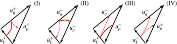
modes have helicities of opposite signs, and thus, he argued, it can be interpreted as a mechanism to transfer energy to smaller scales. In all other cases, the medium wavenumber is unstable and thus there is transfer to both large and small scales. For the particular case that all three modes are of the same helicity, most of the transfer of energy is to the smallest wavenumber, and thus energy is transferred to the large scales. A schematic representation of the direction of energy transfers obtained in Waleffe (Reference Waleffe1992) is shown in figure 1, where the magnitude of the cascade is indicated by the thickness of the arrows. Under the assumption that the statistical behaviour of the flow is controlled by the stability characteristics of these isolated triads (referred to as the ‘instability assumption’), Waleffe (Reference Waleffe1992) was able to draw conclusions on the direction of the energy cascade in turbulent flows. Similar conclusions were reached in the recent work of Rathmann & Ditlevsen (Reference Rathmann and Ditlevsen2016a
), using nonlinear arguments that were based on additional conserved quantities of the isolated triadic interactions. Of course, a large network of triadic interactions as in the Navier–Stokes equation can behave differently from the collection of isolated triads, as has been noted recently by Moffatt (Reference Moffatt2014), and care needs to be taken when interpreting these results.
Transfer of energy in four isolated triadic interactions between different helical modes based on Waleffe (Reference Waleffe1992). The remaining four interactions are obtained by interchanging the
 $\pm$
indices while keeping the same direction of the flux. The thickness of the arrows indicates the magnitude of the transfer of energy.

In order to study the full network of triad interactions and not just isolated triads, one needs to resort to numerical simulations. It is a difficult task to follow the dynamics of different helical modes in numerical simulations, not only due to the computational difficulties involved but also due to the difficulty in interpreting the results. For this reason, most past investigations of helical-mode interactions have been limited to simplified shell models (Ditlevsen & Giuliani Reference Ditlevsen and Giuliani2001a
,Reference Ditlevsen and Giuliani
b
; Lessinnes et al.
Reference Lessinnes, Plunian, Stepanov and Carati2011; De Pietro, Biferale & Mailybaev Reference De Pietro, Biferale and Mailybaev2015; Stepanov et al.
Reference Stepanov, Golbraikh, Frick and Shestakov2015; De Pietro, Mailybaev & Biferale Reference De Pietro, Mailybaev and Biferale2016; Rathmann & Ditlevsen Reference Rathmann and Ditlevsen2016b
; Sahoo, De Pietro & Biferale Reference Sahoo, De Pietro and Biferale2016). The advancement of computational power, however, has allowed investigation of the effect of different helical-mode couplings in direct numerical simulations. The first simulations that followed the evolution of the spectral energy densities
 $E_{k}^{\pm }$
of the two fields
 $u_{k}^{\pm }$
were performed by Chen, Chen & Eyink (Reference Chen, Chen and Eyink2003). It was shown in their work that the transfer of energy to small scales produces a tremendous growth of helicity densities
 $H^{\pm }$
separately which tend to cancel each other and thus restore reflection invariance at small scales.
Biferale, Musacchio & Toschi (Reference Biferale, Musacchio and Toschi2012, Reference Biferale, Musacchio and Toschi2013) investigated with high-resolution numerical simulations a modified version of the Navier–Stokes equations keeping only helicity modes of one sign. In this way, they only kept the triad interactions of the same sign of helicity, which are the ones that suggest an inverse transfer of energy to the large scales. Their system conserves both energy and helicity which are in this case both positive quantities and lead to an inverse cascade of energy and a forward cascade of helicity. More recently, these investigations of decimated models of the Navier–Stokes equations were taken further by explicitly eliminating only a fraction of the
 $\tilde{u} _{k}^{-}$
modes (Sahoo & Biferale Reference Sahoo and Biferale2015; Sahoo, Bonaccorso & Biferale Reference Sahoo, Bonaccorso and Biferale2015). The inverse cascade observed in Biferale et al. (Reference Biferale, Musacchio and Toschi2012) disappeared in the presence of even a tiny fraction of modes of the opposite helicity.
An alternative direction was pursued in Kessar et al. (Reference Kessar, Plunian, Stepanov and Balarac2015), where the effect of different interactions in the Navier–Stokes equations was investigated by suppressing the negative helicity modes by a dynamical forcing function. The dynamical forcing allowed the amount of helicity to be controlled at all scales. These authors showed that interactions from three positive helical modes transfer energy to the large scales. However, in the presence of negative helical modes, of even weak amplitude, the cascade of energy remains forward. Their results were also quantified by calculating the energy fluxes due to the different interactions among helical modes.
In this work, the Navier–Stokes equations are not modified and all interactions are kept, but the effect of different possible interactions is followed by monitoring the decomposed fluxes of both energy and helicity. To this end, large-scale numerical simulations are performed both in the absence of global helicity and in its presence. The details of the helical decomposition and the definition of the decomposed fluxes are given in § 2. Details of the simulations are given in § 3, while the results from the flux decomposition are given in § 4. Conclusions are drawn in the last section.
2 Formulation
The present investigation considers the flow in a triple periodic box of size
 $2\unicode[STIX]{x03C0}L$
, governed by the incompressible Navier–Stokes equation,
 $$\begin{eqnarray}\unicode[STIX]{x2202}_{t}\boldsymbol{u}=\mathbb{P}\left[\boldsymbol{u}\times \boldsymbol{w}\right]+\unicode[STIX]{x1D708}\unicode[STIX]{x1D6E5}\boldsymbol{u}+\boldsymbol{F},\end{eqnarray}$$
where
 $\boldsymbol{u}$
is the three-dimensional incompressible (
 $\unicode[STIX]{x1D735}\boldsymbol{\cdot }\boldsymbol{u}=0$
) velocity field and
 $\boldsymbol{w}$
is the vorticity,
 $\boldsymbol{w}=\unicode[STIX]{x1D735}\times \boldsymbol{u}$
;
 $\boldsymbol{F}$
is the forcing function that acts at some particular length scale
 $\ell _{f}\equiv k_{f}^{-1}$
. Dissipation occurs due to the viscous forces
 $\unicode[STIX]{x1D708}\unicode[STIX]{x1D6E5}\boldsymbol{u}$
, where
 $\unicode[STIX]{x1D708}$
is the viscosity coefficient. Here,
 $\mathbb{P}$
is the projection operator to incompressible flows which can be written as
 $$\begin{eqnarray}\mathbb{P}[\boldsymbol{u}]\equiv -\unicode[STIX]{x1D735}\times \unicode[STIX]{x1D735}\times \unicode[STIX]{x1D6E5}^{-1}\boldsymbol{u}=\boldsymbol{u}-\unicode[STIX]{x1D735}\unicode[STIX]{x1D6E5}^{-1}(\unicode[STIX]{x1D735}\boldsymbol{\cdot }\boldsymbol{u})=\boldsymbol{u}-\unicode[STIX]{x1D735}P.\end{eqnarray}$$
For a given forcing function
 $\boldsymbol{F}$
, this system has one non-dimensional control parameter which is commonly taken to be the Reynolds number
 $Re$
, defined as
 $Re\equiv U\ell _{f}/\unicode[STIX]{x1D708}$
, with
 $U$
the velocity root-mean-square value.
The two quantities conserved by the nonlinearities are the energy
 $E\equiv (1/2)\left\langle \boldsymbol{u}\boldsymbol{\cdot }\boldsymbol{u}\right\rangle$
(where the angular brackets denote space average) and the helicity
 $H\equiv (1/2)\left\langle \boldsymbol{u}\boldsymbol{\cdot }\boldsymbol{w}\right\rangle$
. At steady state, the energy and helicity are injected at the forcing scale
 $\ell _{f}$
and cascade down to the smallest scales where they are dissipated by the viscous forces. The balance of energy injection to dissipation leads to the relations
 $$\begin{eqnarray}\left\langle \boldsymbol{F}\boldsymbol{\cdot }\boldsymbol{u}\right\rangle _{_{T}}=\unicode[STIX]{x1D708}\left\langle \boldsymbol{w}\boldsymbol{\cdot }\boldsymbol{w}\right\rangle _{_{T}}\equiv \unicode[STIX]{x1D716}_{_{E}}\quad \text{and}\quad \left\langle \boldsymbol{F}\boldsymbol{\cdot }\boldsymbol{w}\right\rangle _{_{T}}=\unicode[STIX]{x1D708}\left\langle \boldsymbol{w}\boldsymbol{\cdot }\unicode[STIX]{x1D735}\times \boldsymbol{w}\right\rangle _{_{T}}\equiv \unicode[STIX]{x1D716}_{_{H}},\end{eqnarray}$$
where the angular brackets
 $\left\langle \boldsymbol{\cdot }\right\rangle _{_{T}}$
denote space and time average, and
 $\unicode[STIX]{x1D716}_{_{E}}$
and
 $\unicode[STIX]{x1D716}_{_{H}}$
denote the energy and helicity dissipation rates respectively.
The distribution of the two invariants among scales, and their transfer across scales, is probably best described through the Fourier transform of the fields, defined as
 $$\begin{eqnarray}\tilde{\boldsymbol{u}}_{k}(t)=\frac{1}{(2\unicode[STIX]{x03C0}L)^{3}}\int \text{e}^{-\text{i}\boldsymbol{k}x}\boldsymbol{u}\,\text{d}\boldsymbol{x}^{3},\quad \boldsymbol{u}(t,\boldsymbol{x})=\mathop{\sum }_{k}\text{e}^{+\text{i}\boldsymbol{k}x}\tilde{\boldsymbol{u}}_{k},\end{eqnarray}$$
and similarly for the vorticity field
 $\boldsymbol{w}$
, where
 $\tilde{\boldsymbol{w}}_{k}=i\boldsymbol{k}\times \tilde{\boldsymbol{u}}_{\boldsymbol{k}}$
. The energy and helicity spectra that quantify the distribution of the two invariants in scale space are defined as
 $$\begin{eqnarray}E_{k}=\frac{L}{2}\mathop{\sum }_{k\leqslant |\boldsymbol{q}|<k+1}|\tilde{\boldsymbol{u}}_{\boldsymbol{q}}|^{2},\quad H_{k}=\frac{L}{2}\mathop{\sum }_{k\leqslant |\boldsymbol{q}|<k+1}\tilde{\boldsymbol{u}}_{\boldsymbol{q}}\boldsymbol{\cdot }\tilde{\boldsymbol{w}}_{\boldsymbol{q}}^{\ast },\end{eqnarray}$$
where
 $k$
is a positive integer. They express the distribution of the conserved quantities,
 $E$
and
 $H$
, in wavenumber (and thus also scale) space. It should be noted that since a finite box is considered,
 $E_{k}$
and
 $H_{k}$
are discrete functions of
 $k$
. The factor of
 $L$
in (2.5) is introduced so that
 $E_{k}$
and
 $H_{k}$
have units of energy and helicity density respectively in wavenumber space. In large-Reynolds-number turbulence, both
 $E_{k}$
and
 $H_{k}$
are known to show a
 $k^{-5/3}$
scaling (Brissaud et al.
Reference Brissaud, Frisch, Leorat, Lesieur and Mazure1973; Frisch Reference Frisch1995; Borue & Orszag Reference Borue and Orszag1997).
The magnitudes of the two cascades are measured by the energy and helicity fluxes, which are denoted as
 $\unicode[STIX]{x1D6F1}_{_{E}}(k)$
and
 $\unicode[STIX]{x1D6F1}_{_{H}}(k)$
respectively. They express the rate at which the nonlinearities transfer energy and helicity from the set of wavenumbers
 $\boldsymbol{q}$
that satisfy
 $|\boldsymbol{q}|\leqslant k$
to all larger wavenumbers. Their steady-state value is defined as
 $$\begin{eqnarray}\unicode[STIX]{x1D6F1}_{_{E}}(k)\equiv -\left\langle \boldsymbol{u}_{k}^{{<}}\boldsymbol{\cdot }(\boldsymbol{u}\times \boldsymbol{w})\right\rangle _{_{T}},\quad \unicode[STIX]{x1D6F1}_{_{H}}(k)\equiv -\left\langle \boldsymbol{w}_{\boldsymbol{k}}^{{<}}\boldsymbol{\cdot }(\boldsymbol{u}\times w)\right\rangle _{_{T}},\end{eqnarray}$$
where
 $\boldsymbol{u}^{{<}}(\boldsymbol{x})$
is the velocity field
 $\boldsymbol{u}$
filtered so that all of the Fourier modes
 $\boldsymbol{q}$
with
 $|\boldsymbol{q}|>k$
are removed (see Frisch Reference Frisch1995),
 $$\begin{eqnarray}\boldsymbol{u}_{k}^{{<}}(\boldsymbol{x})=\mathop{\sum }_{|\boldsymbol{q}|<k}\text{e}^{+\text{i}\boldsymbol{q}\boldsymbol{x}}\tilde{\boldsymbol{u}}_{\boldsymbol{ q}},\quad \boldsymbol{w}_{k}^{{<}}(\boldsymbol{x})=\mathop{\sum }_{|\boldsymbol{q}|<k}\text{e}^{+\text{i}\boldsymbol{q}\boldsymbol{x}}\tilde{\boldsymbol{w}}_{\boldsymbol{ q}}.\end{eqnarray}$$
In the limit
 $k\rightarrow \infty$
, the fields
 $\boldsymbol{u}^{{<}}(\boldsymbol{x})$
take their unfiltered value
 $\lim _{k\rightarrow \infty }{\boldsymbol{u}^{{<}}}_{k}=\boldsymbol{u}$
and the two fluxes become zero,
 $\unicode[STIX]{x1D6F1}_{_{E}}(\infty )=\unicode[STIX]{x1D6F1}_{_{H}}(\infty )=0$
, expressing the conservation of energy and helicity by the nonlinearities. Positive values of
 $\unicode[STIX]{x1D6F1}_{_{E}}$
imply that energy cascades forward to the large wavenumbers, while negative values of
 $\unicode[STIX]{x1D6F1}_{_{E}}$
imply that energy cascades inversely to the small wavenumbers. More care needs to be taken for the helicity, because it is a non-sign-definite quantity. Positive values of
 $\unicode[STIX]{x1D6F1}_{_{H}}$
imply that the nonlinearities decrease helicity in the large scales and increase helicity in the small scales. If the helicity is positive at all scales, this can be interpreted as transfer of helicity from large scales to small scales, and thus a forward cascade. If, however, the helicity is negative at all scales, the large-scale helicity will increase in absolute value at the large scales, and thus positive flux can be interpreted as transfer of negative helicity from small scales to large scales, and thus an inverse cascade. It is harder to give an interpretation in terms of a cascade when the helicity is not of the same sign at all scales, and perhaps such an interpretation in terms of a cascade should be avoided. Nonetheless, the helicity flux is still a well-defined quantity, and its interpretation as the rate helicity is changing due to the nonlinearities inside a Fourier-space sphere of a given radius is still valid.
To make contact with the helical-mode decomposition (Craya Reference Craya1958; Lesieur Reference Lesieur1972; Herring Reference Herring1974), we need to express the velocity field as the sum of two fields, one
 $\boldsymbol{u}^{+}$
with positive helicity and one
 $\boldsymbol{u}^{-}$
with negative helicity, as
 $$\begin{eqnarray}\boldsymbol{u}(t,\boldsymbol{x})=\boldsymbol{u}^{+}(t,\boldsymbol{x})+\boldsymbol{u}^{-}(t,\boldsymbol{x})\quad \text{where}~\boldsymbol{u}^{s}(t,\boldsymbol{x})=\mathbb{P}^{s}[\boldsymbol{u}]\end{eqnarray}$$
and
 $\mathbb{P}^{s}$
stand for the projection operators
 $\mathbb{P}^{s}$
of real vector fields
 $\boldsymbol{g}(\boldsymbol{x})$
to the two different bases, defined as
 $$\begin{eqnarray}\boldsymbol{g}^{s}\equiv \mathbb{P}^{s}[\boldsymbol{g}]\equiv \mathop{\sum }_{k}\text{e}^{\text{i}\boldsymbol{k}\boldsymbol{\cdot }x}\boldsymbol{h}_{k}^{s}({\tilde{\boldsymbol{g}}_{k}\boldsymbol{\cdot }h}_{k}^{-s}).\end{eqnarray}$$
Completeness and incompressibility of the bases allow us to write the projection operator to incompressible fields as
 $\mathbb{P}[\boldsymbol{g}]=\mathbb{P}^{+}[\boldsymbol{g}]+\mathbb{P}^{-}[\boldsymbol{g}]$
.
The total energy
 $E$
can be written as
 $E=E^{+}+E^{-}$
, where
 $E^{\pm }=(1/2)\langle \boldsymbol{u}^{\pm }\boldsymbol{\cdot }\boldsymbol{u}^{\pm }\rangle =(1/2)\sum _{k}|\tilde{\boldsymbol{u}}_{k}^{\pm }|^{2}$
. Similarly, the total helicity
 $H$
is written as
 $H=H^{+}+H^{-}$
, where
 $H^{\pm }=(1/2)\langle \boldsymbol{u}^{\pm }\boldsymbol{\cdot }\boldsymbol{w}^{\pm }\rangle =\pm (1/2)\sum _{k}|\boldsymbol{k}||\tilde{\boldsymbol{u}}_{k}^{\pm }|^{2}$
. It should be noted that with this definition
 $H^{+}$
is a positive quantity and
 $H^{-}$
is a negative quantity. The spectral densities
 $E_{k}^{\pm }$
and
 $H_{k}^{\pm }$
associated with the two fields
 $\boldsymbol{u}^{\pm }(\boldsymbol{t},\boldsymbol{x})$
can then be defined similarly to (2.5) as
 $$\begin{eqnarray}E_{k}^{\pm }=\frac{L}{2}\mathop{\sum }_{k\leqslant |\boldsymbol{q}|<k+1}|\tilde{u} _{\boldsymbol{q}}^{\pm }|^{2}\quad \text{and}\quad H_{k}^{\pm }=\pm \frac{L}{2}\mathop{\sum }_{k\leqslant |\boldsymbol{q}|<k+1}|\boldsymbol{q}|\,|\tilde{u} _{\boldsymbol{q}}^{\pm }|^{2}.\end{eqnarray}$$
The evolution of
 $E_{k}^{\pm }$
and
 $H_{k}^{\pm }$
was first investigated in Chen et al. (Reference Chen, Chen and Eyink2003).
Using the helical decomposed fields
 $\boldsymbol{u}^{\pm },\boldsymbol{w}^{\pm }$
, the Navier–Stokes equations can then be written as
 $$\begin{eqnarray}\unicode[STIX]{x2202}_{t}\boldsymbol{u}^{s_{1}}=\mathop{\sum }_{s_{2},s_{3}}\mathbb{P}^{s_{1}}\left[\boldsymbol{u}^{s_{2}}\times \boldsymbol{w}^{s_{3}}\right]+\unicode[STIX]{x1D708}\unicode[STIX]{x0394}\boldsymbol{u}^{s_{1}}+\mathbb{P}^{s_{1}}[\boldsymbol{F}].\end{eqnarray}$$
The nonlinear term of the Navier–Stokes equation is now expressed as the sum of eight terms
 $\mathbb{P}^{s_{1}}[\boldsymbol{u}^{s_{2}}\times \boldsymbol{w}^{s_{3}}]$
which correspond to all possible permutations of the signs
 $s_{i}=\pm 1$
, where
 $i=1,2,3$
. Each of these terms has different properties concerning the evolution of the averaged quantities
 $E^{\pm },H^{\pm }$
. The evolution of the quantities
 $E^{\pm }$
and
 $H^{\pm }$
can be obtained by taking the inner product of the Navier–Stokes equation (2.11) with
 $\boldsymbol{u}^{\pm }$
and
 $\boldsymbol{w}^{\pm }$
respectively, and space averaging. This leads to
 $$\begin{eqnarray}\unicode[STIX]{x2202}_{t}E^{s_{1}}=\mathop{\sum }_{s_{2},s_{3}}\left\langle \boldsymbol{u}^{s_{1}}\boldsymbol{\cdot }\left(\boldsymbol{u}^{s_{2}}\times \boldsymbol{w}^{s_{3}}\right)\right\rangle +\unicode[STIX]{x1D708}\left\langle \boldsymbol{w}^{s_{1}}\boldsymbol{\cdot }\boldsymbol{w}^{s_{1}}\right\rangle +\left\langle \boldsymbol{F}\boldsymbol{\cdot }\boldsymbol{u}^{s_{1}}\right\rangle\end{eqnarray}$$
and
 $$\begin{eqnarray}\unicode[STIX]{x2202}_{t}H^{s_{1}}=\mathop{\sum }_{s_{2},s_{3}}\left\langle \boldsymbol{w}^{s_{1}}\boldsymbol{\cdot }\left(\boldsymbol{u}^{s_{2}}\times \boldsymbol{w}^{s_{3}}\right)\right\rangle +\unicode[STIX]{x1D708}\left\langle \boldsymbol{w}^{s_{1}}\boldsymbol{\cdot }\unicode[STIX]{x0394}\boldsymbol{u}^{s_{1}}\right\rangle +\left\langle \boldsymbol{F}\boldsymbol{\cdot }\boldsymbol{w}^{s_{1}}\right\rangle .\end{eqnarray}$$
It is evident from the expressions above that the nonlinear terms
 $\mathbb{P}^{s_{1}}[\boldsymbol{u}^{s_{2}}\times \boldsymbol{w}^{s_{3}}]$
in the sum with
 $s_{1}=s_{2}=s$
conserve
 $E^{\pm }$
independently (i.e.
 $\langle \boldsymbol{u}^{s}\boldsymbol{\cdot }(\boldsymbol{u}^{s}\times \boldsymbol{w}^{s_{3}})\rangle =0$
), but not
 $H^{\pm }$
, and the nonlinear terms with
 $s_{1}=s_{3}=s$
conserve
 $H^{\pm }$
independently (i.e.
 $\langle \boldsymbol{w}^{s}\boldsymbol{\cdot }(\boldsymbol{u}^{s_{2}}\times \boldsymbol{w}^{s})\rangle =0$
), but not
 $E^{\pm }$
. Thus, only the nonlinear terms
 $\mathbb{P}^{s}[\boldsymbol{u}^{s}\times \boldsymbol{w}^{s}]$
in (2.11) with
 $s=\pm 1$
conserve all four quantities
 $E^{\pm },H^{\pm }$
independently. The terms
 $\langle \boldsymbol{u}^{s}\boldsymbol{\cdot }(\boldsymbol{u}^{-s}\times \boldsymbol{w}^{s_{3}})\rangle$
that do not conserve the energies
 $E^{\pm }$
and the terms
 $\langle \boldsymbol{w}^{s}\boldsymbol{\cdot }(\boldsymbol{u}^{s_{2}}\times \boldsymbol{w}^{-s})\rangle$
that do not conserve the helicities
 $H^{\pm }$
are responsible for transferring energy and helicity from one field
 $\boldsymbol{u}^{+}$
to the other
 $\boldsymbol{u}^{-}$
keeping the total energy and the total helicity unaltered.
With this in mind, we can decompose the energy and the helicity flux into eight partial fluxes as
 $$\begin{eqnarray}\unicode[STIX]{x1D6F1}_{_{E}}^{s_{1},s_{2},s_{3}}(k)=-\left\langle \boldsymbol{u}_{k}^{s_{1}<}\boldsymbol{\cdot }\left(\boldsymbol{u}^{s_{2}}\times \boldsymbol{w}^{s_{3}}\right)\right\rangle _{_{T}},\quad \unicode[STIX]{x1D6F1}_{_{H}}^{s_{1},s_{2},s_{3}}(k)=-\left\langle \boldsymbol{w}_{k}^{s_{1}<}\boldsymbol{\cdot }\left(\boldsymbol{u}^{s_{2}}\times \boldsymbol{w}^{s_{3}}\right)\right\rangle _{_{T}},\end{eqnarray}$$
where the
 $\boldsymbol{u}_{k}^{s<}$
express the two helical fields
 $\boldsymbol{u}_{k}^{s}$
given in (2.8) filtered so that only Fourier modes inside a sphere of radius
 $k$
are kept. The decomposition of the energy flux has also been used in Kessar et al. (Reference Kessar, Plunian, Stepanov and Balarac2015), while the partial helicity fluxes are presented for the first time here. The total energy and helicity fluxes can be recovered by summing these partial fluxes,
 $$\begin{eqnarray}\unicode[STIX]{x1D6F1}_{_{E}}(k)=\mathop{\sum }_{s_{1},s_{2},s_{3}}\unicode[STIX]{x1D6F1}_{_{E}}^{s_{1},s_{2},s_{3}}(k)\quad \text{and}\quad \unicode[STIX]{x1D6F1}_{_{H}}(k)=\mathop{\sum }_{s_{1},s_{2},s_{3}}\unicode[STIX]{x1D6F1}_{_{H}}^{s_{1},s_{2},s_{3}}(k).\end{eqnarray}$$
From these eight energy fluxes, only the four
 $\unicode[STIX]{x1D6F1}_{_{E}}^{s,s,s_{3}}$
come from conservative terms for
 $E^{\pm }$
, and we will refer to them as conservative fluxes. They have the property
 $$\begin{eqnarray}\lim _{k\rightarrow \infty }\unicode[STIX]{x1D6F1}_{_{E}}^{s,s,s_{3}}(k)=0\,.\end{eqnarray}$$
The remaining four partial fluxes
 $\unicode[STIX]{x1D6F1}_{_{E}}^{s,-s,s_{3}}$
transfer energy among the two helical fields
 $\boldsymbol{u}^{\pm }$
and will be referred to as trans-helical energy fluxes. These need to be added in pairs to result in conservative fluxes,
 $\unicode[STIX]{x1D6F1}_{_{E}}^{s_{3},th}=\unicode[STIX]{x1D6F1}_{_{E}}^{s,-s,s_{3}}+\unicode[STIX]{x1D6F1}_{_{E}}^{-s,s,s_{3}}$
. We will refer to
 $\unicode[STIX]{x1D6F1}_{_{E}}^{s_{3},th}$
as the averaged trans-helical energy flux. It is this averaged trans-helical energy flux
 $\unicode[STIX]{x1D6F1}_{_{E}}^{s,th}$
that has the property
 $$\begin{eqnarray}\lim _{k\rightarrow \infty }\unicode[STIX]{x1D6F1}_{_{E}}^{s_{3},th}(k)=0.\end{eqnarray}$$
For the fluxes
 $\unicode[STIX]{x1D6F1}_{_{E}}^{s,-s,s_{3}}$
, the limit
 $\lim _{k\rightarrow \infty }\unicode[STIX]{x1D6F1}_{_{E}}^{s,-s,s_{3}}$
is not in general zero but expresses the rate
 ${\mathcal{T}}_{_{E}}^{s_{3}}$
at which
 $E^{+}$
energy is transferred to
 $E^{-}$
by interacting with the field
 $\boldsymbol{w}^{s_{3}}$
,
 $$\begin{eqnarray}{\mathcal{T}}_{_{E}}^{s_{3}}=\lim _{k\rightarrow \infty }\unicode[STIX]{x1D6F1}_{_{E}}^{+,-,s_{3}}(k)=-\lim _{k\rightarrow \infty }\unicode[STIX]{x1D6F1}_{_{E}}^{-,+,s_{3}}(k)\,.\end{eqnarray}$$
The total rate of transfer of
 $E^{+}$
energy to
 $E^{-}$
energy is
 ${\mathcal{T}}_{_{E}}={\mathcal{T}}_{_{E}}^{+}+{\mathcal{T}}_{_{E}}^{-}$
.
Similarly, for the helicity, the fluxes
 $\unicode[STIX]{x1D6F1}_{_{H}}^{s,s_{2},s}$
come from conservative terms and satisfy
 $$\begin{eqnarray}\lim _{k\rightarrow \infty }\unicode[STIX]{x1D6F1}_{_{H}}^{s,s_{2},s}(k)=0.\end{eqnarray}$$
The fluxes
 $\unicode[STIX]{x1D6F1}_{_{H}}^{s,s_{2},-s}$
that transfer helicity from
 $H^{+}$
to
 $H^{-}$
and vice versa will be referred to as trans-helical helicity fluxes. They need to be paired with the averaged trans-helical helicity flux
 $\unicode[STIX]{x1D6F1}_{_{H}}^{s_{2},th}=\unicode[STIX]{x1D6F1}_{_{E}}^{s,s_{2},-s}+\unicode[STIX]{x1D6F1}_{_{E}}^{-s,s_{2},s}$
to take a conservative form,
 $$\begin{eqnarray}\lim _{k\rightarrow \infty }\unicode[STIX]{x1D6F1}_{_{H}}^{s_{2},th}(k)=0.\end{eqnarray}$$
Due to the negative sign of
 $H^{-}$
, an increase of
 $H^{-}$
in absolute value implies an equal increase in
 $H^{+}$
, so that total helicity is conserved. The total rate of generation
 ${\mathcal{G}}_{_{H}}^{s}$
of
 $H^{+}$
helicity (equal to the rate of generation of
 $|H^{-}|$
) through the interaction with the velocity fields
 $\boldsymbol{u}^{s}$
is defined as
 $$\begin{eqnarray}{\mathcal{G}}_{_{H}}^{s}=\lim _{k\rightarrow \infty }\unicode[STIX]{x1D6F1}_{_{H}}^{-,s,+}=-\lim _{k\rightarrow \infty }\unicode[STIX]{x1D6F1}_{_{H}}^{+,s,-}.\end{eqnarray}$$
The total generation rate of
 $H^{+}$
(and thus
 $H^{-}$
) is then given by
 ${\mathcal{G}}_{_{H}}={\mathcal{G}}_{_{H}}^{+}+{\mathcal{G}}_{_{H}}^{-}$
.
This decomposition of the fluxes allows us to study the roles of different classes of interactions in a turbulent flow. However, we need to stress here that the classification of the triads in eight classes presented in Waleffe (Reference Waleffe1992) is not in exact correspondence with the eight different energy and helicity fluxes presented here. This is because the Waleffe (Reference Waleffe1992) classification of triads is based on the magnitude of the wavevectors and the helicity of the modes involved. The present flux decomposition, on the other hand, provides a classification of the interactions based on the different nonlinearities that appear when the helical decomposition is made, and has no reference to the magnitude of the wavevectors involved. Furthermore, the flux
 $\unicode[STIX]{x1D6F1}_{_{E}}^{s_{1},s_{2},s_{3}}$
expresses the flux of energy
 $E^{s_{1}}$
to
 $E^{s_{2}}$
due to the interaction
 $\mathbb{P}^{s_{1}}[\boldsymbol{u}^{s_{2}}\times \boldsymbol{w}^{s_{3}}]$
for which the field
 $\boldsymbol{w}^{s_{3}}$
only acts as a ‘catalyst’ and does not exchange energy. Similarly, for the flux
 $\unicode[STIX]{x1D6F1}_{_{H}}^{s_{1},s_{2},s_{3}}$
, the field
 $\boldsymbol{u}^{s_{2}}$
only acts as a ‘catalyst’ for the helicity transfer. This differs from the analysis of individual triadic interactions, which is treated as a closed system and the simultaneous exchange of energy and helicity between all three modes is considered. The only contact made by the two classifications involves the same-helicity interactions/triads, where the magnitude of the wavevectors becomes irrelevant for the Waleffe classification. With the present description, thus, we can link the
 $\unicode[STIX]{x1D6F1}_{_{E}}^{s,s,s}$
and
 $\unicode[STIX]{x1D6F1}_{_{H}}^{s,s,s}$
fluxes with the same-helicity type of interactions of Waleffe (Reference Waleffe1992) (type I depicted in figure 1). However, we cannot link the remaining fluxes with the other types of interactions (types II, III and IV in figure 1) because the fluxes
 $\unicode[STIX]{x1D6F1}_{_{E}}^{s_{1},s_{2},s_{3}}$
and
 $\unicode[STIX]{x1D6F1}_{_{H}}^{s_{1},s_{2},s_{3}}$
only provide information about the direction of the cascade and do not allow us to distinguish between the magnitudes of the three wavevectors involved in the interactions. Such a comparison could be made possible to some extent by considering shell-to-shell energy transfers (Alexakis, Mininni & Pouquet Reference Alexakis, Mininni and Pouquet2005; Verma et al.
Reference Verma, Ayyer, Debliquy, Kumar and Chandra2005; Mininni, Alexakis & Pouquet Reference Mininni, Alexakis and Pouquet2006), which is not attempted here.
3 Simulations
To unfold the implications of the proposed decompositions in the previous section, we performed numerical simulations of the Navier–Stokes equations in a triple periodic cubic domain of size
 $2\unicode[STIX]{x03C0}$
at a resolution of
 $1536^{3}$
. The simulations were performed using the pseudo-spectral Ghost code (Mininni et al.
Reference Mininni, Rosenberg, Reddy and Pouquet2011) with a fourth-order Runge–Kutta method for the time advancement and a 2/3 rule for dealiasing. The flow was forced by a mechanical forcing
 $\boldsymbol{F}$
which consisted only of Fourier modes with wavenumbers
 $\boldsymbol{q}$
such that
 $k_{f}\leqslant |\boldsymbol{q}|\leqslant k_{f}+1$
with
 $k_{f}=4$
. This relatively high wavenumber of the forcing was chosen so that not only was the forward cascade studied but the behaviour of the flow at scales larger than the forcing was also examined. The amplitude of the forcing was fixed at unity
 $\Vert \boldsymbol{F}\Vert =1$
and the phases of the Fourier modes were changed randomly at fixed time intervals
 $\unicode[STIX]{x1D70F}_{f}=0.1$
. Two different forcing functions were considered; in the first, the Fourier modes of the forcing were not helical (so
 $\Vert \mathbb{P}^{+}[\boldsymbol{F}]\Vert =\Vert \mathbb{P}^{-}[\boldsymbol{F}]\Vert$
at each instant of time), while, in the second, each Fourier mode was fully helical with positive helicity (i.e.
 $\boldsymbol{F}=\mathbb{P}^{+}[\boldsymbol{F}]$
and
 $\mathbb{P}^{-}[\boldsymbol{F}]=0$
). All of the parameters of the runs and the basic observables are given in table 1. To reduce computational time, the runs were started using as initial conditions the results from runs with smaller
 $Re$
(and smaller grid) and were continued for 12 turnover times (
 $\unicode[STIX]{x1D70F}_{u}=1/\Vert \boldsymbol{u}\Vert k_{f}$
) after the first peak of energy dissipation appeared.
Parameters of the numerical simulations for the helical and non-helical cases. In both simulations,
 $N=1536^{3}$
;
 $k_{m}=N/3$
is the maximum wavenumber and
 $\unicode[STIX]{x1D702}=(\unicode[STIX]{x1D708}^{3}/\unicode[STIX]{x1D716})^{1/4}$
is the Kolmogorov length scale.

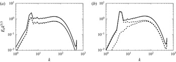
The resulting energy spectra of these runs compensated by
 $k^{-5/3}$
are shown in figure 2 with a solid black line. The spectra show a close to
 $k^{-5/3}$
behaviour, although a large bottleneck makes the spectra deviate from this value. The bottleneck effect, although not fully understood, is very well documented (Herring et al.
Reference Herring, Schertzer, Lesieur, Newman, Chollet and Larcheveque1982; Falkovich Reference Falkovich1994; Lohse & Müller-Groeling Reference Lohse and Müller-Groeling1995; Martinez et al.
Reference Martinez, Chen, Doolen, Kraichnan, Wang and Zhou1997; Kurien, Taylor & Matsumoto Reference Kurien, Taylor and Matsumoto2004), and it is argued that it is related to the quenching of local interactions close to the dissipative scales which leads to a ‘pile-up’ of energy at these scales. It is stronger in the helical case which dominates most of the spectrum.
Energy spectra compensated by
 $k^{5/3}$
for the non-helical case (a) and the helical case (b). The solid line shows the total energy spectrum
 $E_{k}=E_{k}^{+}+E_{k}^{-}$
and the dashed lines show the two spectra
 $E_{k}^{\pm }$
. For the non-helical case, the spectra
 $E_{k}^{\pm }$
are indistinguishable, while, for the helical case,
 $E_{k}^{+}$
is significantly larger at small
 $k$
but reaches equipartition with
 $E_{k}^{-}$
at large
 $k$
. Both spectra show a bottleneck at large
 $k$
, which is more pronounced for the helical case.

The dashed lines in figure 2 show the spectra
 $E_{k}^{\pm }$
given in (2.10). For the non-helical case (a), the two spectra are indistinguishable and the two fields
 $\boldsymbol{u}^{+}$
and
 $\boldsymbol{u}^{-}$
have identical statistics. For the helical case (b), the spectrum
 $E_{k}^{+}$
(top dashed line) for the positive helical field dominates at the large scales. This is expected since the forcing injects energy only at the
 $\boldsymbol{u}^{+}$
modes. It is also worth noting that the
 $E_{k}^{+}$
spectrum shows a clearer
 $k^{-5/3}$
scaling. The spectrum
 $E_{k}^{-}$
for the negative helical field is sub-dominant at large scales but increases and reaches equipartition with
 $E_{k}^{+}$
at large wavenumbers, restoring parity invariance at small scales.
4 Fluxes
The results of these simulations were used to calculate the partial fluxes defined in (2.14). The calculation was performed at runtime at frequent time intervals, and the results were time averaged at the end. The calculation was performed in the following way. At each output time, the fields
 $\boldsymbol{u}^{s_{1}}$
,
 $\boldsymbol{w}^{s_{1}}$
and the four nonlinear terms
 $\boldsymbol{u}^{s_{2}}\times \boldsymbol{w}^{s_{3}}$
were calculated. Then, the inner product in (2.14) with
 $\boldsymbol{u}^{s_{1}<}$
and
 $\boldsymbol{w}^{s_{1}<}$
was obtained by filtering
 $\boldsymbol{u}^{s_{1}}$
and
 $\boldsymbol{w}^{s_{1}}$
. This procedure is eight times as costly as one Runge–Kutta time step, but since the fluxes were not calculated every time step, it did not lead to a significant slowdown of the code. The results were finally averaged over the steady state, and are presented in the subsections that follow.
4.1 Energy fluxes
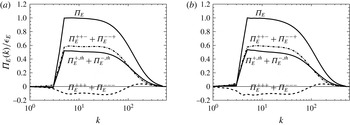
First, the energy fluxes are examined. Figure 3 shows with a solid line the total energy flux for the non-helical run in (a) and for the helical run in (b). The partial fluxes
 $\unicode[STIX]{x1D6F1}_{_{E}}^{+++}+\unicode[STIX]{x1D6F1}_{_{E}}^{---}$
are shown with a dashed line,
 $\unicode[STIX]{x1D6F1}_{_{E}}^{++-}+\unicode[STIX]{x1D6F1}_{_{E}}^{--+}$
are shown with a dash–dot line, while the averaged trans-helical fluxes
 $\unicode[STIX]{x1D6F1}_{_{E}}^{+,th}+\unicode[STIX]{x1D6F1}_{_{E}}^{-,th}$
are shown with a dash–dot–dot–dot line. The fluxes have been summed (symmetrized) over the two signs for clarity. This has no effect on the non-helical flow, for which the two fields have identical statistical properties, but it does have an effect on the results of the helical run which we analyse further later in the text.
Total energy flux
 $\unicode[STIX]{x1D6F1}_{E}$
(solid line) and the symmetrized energy fluxes
 $\unicode[STIX]{x1D6F1}_{E}^{+++}+\unicode[STIX]{x1D6F1}_{E}^{---}$
(dashed line),
 $\unicode[STIX]{x1D6F1}_{E}^{++-}+\unicode[STIX]{x1D6F1}_{E}^{--+}$
(dash–dot line) and
 $\unicode[STIX]{x1D6F1}_{E}^{+,th}+\unicode[STIX]{x1D6F1}_{E}^{-,th}$
(dash–dot–dot–dot line) for the non-helical (a) and helical (b) cases.

Three striking points can be observed from figure 3. First, the three symmetrized partial fluxes shown in this figure are approximately constant in the inertial range. This is not a trivial result because conservation of energy implies constancy of only the total energy flux. A second observation is that the two simulations, despite having different distributions of energy among helical modes, have identical symmetrized partial fluxes. Finally, and perhaps most striking, is the fact that the fluxes
 $\unicode[STIX]{x1D6F1}_{_{E}}^{+++}+\unicode[STIX]{x1D6F1}_{_{E}}^{---}$
are constant and negative. The negative sign of this flux has also been observed in Kessar et al. (Reference Kessar, Plunian, Stepanov and Balarac2015), but not at sufficiently large
 $Re$
to claim it to be constant. This negative flux implies that in turbulence, hidden inside the forward cascade of the total energy there is a process that transfers energy back to the large scales at a constant rate across scales. This is also in agreement with the prediction of Waleffe (Reference Waleffe1992) that same-helicity interactions transfer energy to large scales. The amplitude of this inverse flux is approximately 10 % of the total flux. This percentage is the same for both simulations and is possibly universal. The
 $\unicode[STIX]{x1D6F1}_{E}^{++-}+\unicode[STIX]{x1D6F1}_{E}^{--+}$
and
 $\unicode[STIX]{x1D6F1}_{E}^{+,th}+\unicode[STIX]{x1D6F1}_{E}^{-,th}$
fluxes are almost equal and positive for all wavenumbers in the inertial range, with a slight excess of flux for
 $\unicode[STIX]{x1D6F1}_{_{E}}^{++-}+\unicode[STIX]{x1D6F1}_{_{E}}^{--+}$
over
 $\unicode[STIX]{x1D6F1}_{_{E}}^{+,th}+\unicode[STIX]{x1D6F1}_{_{E}}^{-,th}$
. These fluxes are responsible for the total forward flux of energy.
At scales larger than the forcing scale,
 $\unicode[STIX]{x1D6F1}_{_{E}}^{+++}+\unicode[STIX]{x1D6F1}_{_{E}}^{---}$
remains negative, and it is balanced by the other two fluxes
 $\unicode[STIX]{x1D6F1}_{E}^{++-}+\unicode[STIX]{x1D6F1}_{E}^{--+}$
and
 $\unicode[STIX]{x1D6F1}_{E}^{+,th}+\unicode[STIX]{x1D6F1}_{E}^{-,th}$
, leading to a zero total flux for
 $k<k_{f}$
. Large scales thus reach an equilibrium by receiving energy from the small scales by
 $\mathbb{P}^{s}[\boldsymbol{u}^{s}\times \boldsymbol{w}^{s}]$
interactions and losing energy to the small scales by the remaining interactions. At the viscous scales, the fluxes
 $\unicode[STIX]{x1D6F1}_{_{E}}^{+++}+\unicode[STIX]{x1D6F1}_{_{E}}^{---}$
change sign and become positive. This is because at these scales the energy spectrum is very steep and thus these interactions also transfer energy forward.
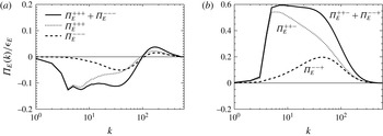
(a) Symmetrized energy flux
 $\unicode[STIX]{x1D6F1}_{E}^{+++}+\unicode[STIX]{x1D6F1}_{E}^{---}$
(solid line),
 $\unicode[STIX]{x1D6F1}_{E}^{+++}$
(dotted line) and
 $\unicode[STIX]{x1D6F1}_{E}^{---}$
(dashed line) for the helical run. (b) Symmetrized energy flux
 $\unicode[STIX]{x1D6F1}_{E}^{++-}+\unicode[STIX]{x1D6F1}_{E}^{--+}$
(solid line),
 $\unicode[STIX]{x1D6F1}_{E}^{++-}$
(dotted line) and
 $\unicode[STIX]{x1D6F1}_{E}^{--+}$
(dashed line) for the same run.

As discussed before, in the non-helical run, the fields
 $u^{+}$
and
 $u^{-}$
have the same statistical properties and the fluxes obey
 $\unicode[STIX]{x1D6F1}_{E}^{s_{1},s_{2},s_{3}}=\unicode[STIX]{x1D6F1}_{E}^{-s_{1},-s_{2},-s_{3}}$
. This is not true for the helical case, for which the
 $\tilde{u} ^{+}$
modes have different distributions from the
 $\tilde{u} ^{-}$
modes. To show this difference, figure 4(a) shows the symmetrized flux
 $\unicode[STIX]{x1D6F1}_{E}^{+++}+\unicode[STIX]{x1D6F1}_{E}^{---}$
along with the individual partial fluxes
 $\unicode[STIX]{x1D6F1}_{E}^{+++}$
and
 $\unicode[STIX]{x1D6F1}_{E}^{---}$
. At large scales where the positively helical modes dominate, most of the inverse energy flux is driven by
 $\unicode[STIX]{x1D6F1}_{E}^{+++}$
, but at smaller scales the two fluxes become equal. A similar behaviour is shown in figure 4(b) for the fluxes
 $\unicode[STIX]{x1D6F1}_{E}^{++-}$
and
 $\unicode[STIX]{x1D6F1}_{E}^{--+}$
. At large scales, the
 $\unicode[STIX]{x1D6F1}_{E}^{++-}$
dominates because it involves two
 $\tilde{u} ^{+}$
modes and one
 $\tilde{u} ^{-}$
mode, so it is stronger than
 $\unicode[STIX]{x1D6F1}_{E}^{--+}$
which involves only one
 $\tilde{u} ^{+}$
mode. At small scales, however, that parity invariance is restored and the two fluxes become equal.
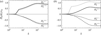
The four trans-helical energy fluxes for the non-helical (a) and helical (b) cases:
 $\unicode[STIX]{x1D6F1}_{E}^{-+-}$
(solid line),
 $\unicode[STIX]{x1D6F1}_{E}^{+-+}$
(dotted line),
 $\unicode[STIX]{x1D6F1}_{E}^{+--}$
(dashed line),
 $\unicode[STIX]{x1D6F1}_{E}^{-++}$
(dash–dot line).

The trans-helical energy fluxes
 $\unicode[STIX]{x1D6F1}_{E}^{-+-}$
,
 $\unicode[STIX]{x1D6F1}_{E}^{+-+}$
,
 $\unicode[STIX]{x1D6F1}_{E}^{+--}$
,
 $\unicode[STIX]{x1D6F1}_{E}^{-++}$
are plotted in figure 5, for the non-helical case in figure 5(a) and the helical case in figure 5(b). As discussed in the introduction, these fluxes originate from terms that do not conserve the individual energies
 $E^{\pm }$
but transfer energy from modes of one helicity sign to modes of the opposite helicity. More precisely,
 $\unicode[STIX]{x1D6F1}_{E}^{+--}$
and
 $\unicode[STIX]{x1D6F1}_{E}^{+-+}$
represent the rate at which
 $E^{+}$
energy is transferred from the large scales to
 $E^{-}$
energy (at all scales) through the interaction with the
 $\boldsymbol{w}^{-}$
and
 $\boldsymbol{w}^{+}$
fields respectively. Similarly,
 $\unicode[STIX]{x1D6F1}_{E}^{-+-}$
and
 $\unicode[STIX]{x1D6F1}_{E}^{-++}$
represent the transfer rate of
 $E^{-}$
energy from the large scales to
 $E^{+}$
energy through the interaction with the
 $\boldsymbol{w}^{-}$
and
 $\boldsymbol{w}^{+}$
fields respectively. Energy conservation then implies that at
 $k\rightarrow \infty$
we have
 $$\begin{eqnarray}\lim _{k\rightarrow \infty }\unicode[STIX]{x1D6F1}_{E}^{-+-}=-\lim _{k\rightarrow \infty }\unicode[STIX]{x1D6F1}_{E}^{+--}\quad \text{and}\quad \lim _{k\rightarrow \infty }\unicode[STIX]{x1D6F1}_{E}^{-++}=-\lim _{k\rightarrow \infty }\unicode[STIX]{x1D6F1}_{E}^{+-+}\end{eqnarray}$$
as a direct consequence of (2.17).
We begin with the non-helical case. As can be seen,
 $\unicode[STIX]{x1D6F1}_{E}^{+-+}$
is positive at all scales. This implies that the interactions
 $\mathbb{P}^{+}[\boldsymbol{u}^{-}\times \boldsymbol{w}^{+}]$
remove energy from the positively helical large-scale modes. On the contrary,
 $\unicode[STIX]{x1D6F1}_{E}^{+--}$
is negative at all scales, and this implies that the interactions
 $\mathbb{P}^{+}[\boldsymbol{u}^{-}\times \boldsymbol{w}^{-}]$
increase the energy of the positively helical large-scale modes. The same conclusion can be drawn for
 $\unicode[STIX]{x1D6F1}_{E}^{-+-}$
and
 $\unicode[STIX]{x1D6F1}_{E}^{-++}$
for the energy of the negatively helical modes. The end values at
 $k\rightarrow \infty$
of the flux
 $\unicode[STIX]{x1D6F1}_{E}^{+-s}$
indicate the total rate
 ${\mathcal{T}}_{_{E}}^{s}$
at which the energy is transferred from the
 $\boldsymbol{u}^{+}$
field to the
 $\boldsymbol{u}^{-}$
field through the interactions
 $\mathbb{P}^{+}[{\boldsymbol{u}^{-}\times \boldsymbol{w}}^{s}]$
. What is observed is that
 ${\mathcal{T}}_{_{E}}^{+}=\lim _{k\rightarrow \infty }\unicode[STIX]{x1D6F1}_{E}^{+,-,+}(k)>0$
; thus, this transfer removes energy from the positively helical field, while
 ${\mathcal{T}}_{_{E}}^{-}=\lim _{k\rightarrow \infty }\unicode[STIX]{x1D6F1}_{E}^{+,-,-}(k)<0$
, and thus this transfer feeds with energy the modes with positive helicity. In other words, interactions with modes
 $\tilde{\boldsymbol{w}}_{k}^{s}$
tend to transfer energy from
 $E^{s}$
to
 $E^{-s}$
. At the non-helical steady state, the interactions reach an equilibrium, with zero net transfer of energy across the two fields. This is realized by observing that in the limit
 $k\rightarrow \infty$
, we have
 $\unicode[STIX]{x1D6F1}_{E}^{-+-}\simeq \unicode[STIX]{x1D6F1}_{E}^{+-+}$
and
 $\unicode[STIX]{x1D6F1}_{E}^{-++}\simeq \unicode[STIX]{x1D6F1}_{E}^{+--}$
.
This is no longer true for the helical case. Although these fluxes have the same sign as in the non-helical case, their amplitudes are not equal. The interactions that involve more (i.e. two) positive helical modes dominate in absolute magnitude over the interactions with more (i.e. two) negative helical modes. Thus, the fluxes
 $\unicode[STIX]{x1D6F1}_{E}^{+-+},\unicode[STIX]{x1D6F1}_{E}^{-++}$
that lead to the transfer of energy
 ${\mathcal{T}}_{_{E}}^{+}$
from the positive helical modes to the negative helical modes dominate over the fluxes
 $\unicode[STIX]{x1D6F1}_{E}^{+--},\unicode[STIX]{x1D6F1}_{E}^{-+-}$
that display a transfer from
 $E^{-}$
to
 $E^{+}$
. This indicates how parity invariance is recovered at small scales: the initial excess of
 $E^{+}$
energy favours interactions with two
 $\boldsymbol{u}^{+}$
modes, and this leads to a faster transfer
 ${\mathcal{T}}_{_{E}}^{+}$
(from
 $E^{+}$
to
 $E^{-}$
) compared with
 ${\mathcal{T}}_{_{E}}^{-}$
(from
 $E^{-}$
to
 $E^{+}$
) until the balance is restored. Furthermore, the end values in the limit
 $k\rightarrow \infty$
indicate that
 $\unicode[STIX]{x1D6F1}_{E}^{-+-}=-\unicode[STIX]{x1D6F1}_{E}^{+--}\simeq 1/2\unicode[STIX]{x1D6F1}_{E}^{+-+}=-1/2\unicode[STIX]{x1D6F1}_{E}^{-++}\simeq 1/2\unicode[STIX]{x1D716}_{_{E}}$
. Thus, the total rate of transfer of energy from
 $\boldsymbol{u}_{\boldsymbol{k}}^{+}$
modes to
 $\boldsymbol{u}_{\boldsymbol{k}}^{-}$
modes is
 ${\mathcal{T}}=\lim _{k\rightarrow \infty }(\unicode[STIX]{x1D6F1}_{E}^{+-+}+\unicode[STIX]{x1D6F1}_{E}^{+--})\simeq 1/2\unicode[STIX]{x1D716}_{_{E}}$
. This can be explained with the following reasoning. While energy is injected only in the
 $\boldsymbol{u}^{+}$
field, the two fields dissipate energy at the same rate since parity invariance is restored at small scales. In order to achieve this, half of the injected energy at the
 $\boldsymbol{u}_{\boldsymbol{k}}^{+}$
modes has to be transferred to the unforced
 $\boldsymbol{u}_{\boldsymbol{k}}^{-}$
modes.
4.2 Helicity fluxes
In this section, we focus on the flux of helicity. The important difference between the energy and helicity fluxes is the negative sign of
 $H^{-}$
. For the energies
 $E^{\pm }$
, the nonlinear interactions can increase
 $E^{-}$
only at the cost of decreasing
 $E^{+}$
, keeping their sum the same. For the helicities
 $H^{\pm }$
, the negative
 $H^{-}$
can be increased in absolute value by simultaneously increasing
 $H^{+}$
, thus generating both
 $H^{+}$
and
 $H^{-}$
. This generation of
 $H^{\pm }$
is important for the sustainment of the forward energy cascade. As the energies
 $E^{\pm }$
are transferred to small scales, the helicities
 $H^{\pm }$
that scale like
 $H_{k}^{\pm }=\pm kE_{k}^{\pm }$
have to increase. This can be achieved through the interactions
 $\langle \boldsymbol{w}^{s}\boldsymbol{\cdot }(\boldsymbol{u}^{s_{2}}\times \boldsymbol{w}^{-s})\rangle$
which do not conserve
 $H^{\pm }$
individually. This simultaneous generation of
 $H^{+}$
and
 $H^{-}$
is measured by the trans-helical fluxes
 $\unicode[STIX]{x1D6F1}_{_{H}}^{s,s_{2},-s}$
. The remaining fluxes conserve
 $H^{\pm }$
individually and can be interpreted as cascades. The fluxes
 $\unicode[STIX]{x1D6F1}_{H}^{+,s,+}$
originate from terms that conserve
 $H^{+}$
that is a positive quantity. Thus these fluxes give a measure of the forward cascade of
 $H^{+}$
when they are positive and of the inverse cascade of
 $H^{+}$
when they are negative. Similarly the fluxes
 $\unicode[STIX]{x1D6F1}_{H}^{-,s,-}$
, originate from terms that conserve
 $H^{-}$
which is a negative quantity. Thus, these fluxes can also be interpreted as measures of a cascade, but due to the negative sign of
 $H^{-}\leqslant 0$
, positive values imply an inverse cascade of
 $H^{-}$
while negative values imply a forward cascade of
 $H^{-}$
.
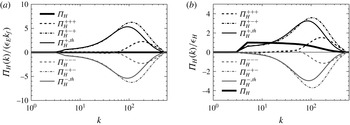
Figure 6 shows with a solid line the total helicity flux for the non-helical run in figure 6(a) and for the helical run in figure 6(b). For the non-helical case, the total helicity flux is of course zero, while for the helical flow, a constant positive flux of helicity is observed in the inertial range. Since the helicity of the flow is strictly positive at all scales, this positive flux can be interpreted as a forward cascade of helicity. The partial fluxes of helicity defined in (2.14) are shown by the non-solid lines.
None of the partial fluxes appear to be constant in the inertial range; instead, they appear to increase as the viscous scales are approached, and then decrease again after the viscous cutoff. The fluxes of helicity due to same-helicity interactions,
 $\unicode[STIX]{x1D6F1}_{H}^{+++},\unicode[STIX]{x1D6F1}_{H}^{---}$
, are almost zero in the inertial range, implying that they drive a weak or no cascade of helicity. This is true for both the helical and the non-helical flow. In the dissipation range where the spectra are much steeper,
 $\unicode[STIX]{x1D6F1}_{H}^{+++}$
becomes positive and
 $\unicode[STIX]{x1D6F1}_{H}^{---}$
negative, transferring thus
 $H^{+}$
and
 $H^{-}$
to the small scales. The fluxes
 $\unicode[STIX]{x1D6F1}_{H}^{+-+}$
,
 $\unicode[STIX]{x1D6F1}_{H}^{-+-}$
, which also individually conserve
 $H^{\pm }$
, are non-zero but not constant. The flux
 $\unicode[STIX]{x1D6F1}_{H}^{+-+}$
which measures the transport of
 $H^{+}\geqslant 0$
is positive and
 $\unicode[STIX]{x1D6F1}_{H}^{-+-}$
which measures the transport of
 $H^{-}\leqslant 0$
is negative; thus, the quantities
 $H^{\pm }$
are transported to the small scales, i.e. forward cascading. Finally, the averaged trans-helical fluxes
 $\unicode[STIX]{x1D6F1}_{H}^{+,th}$
and
 $\unicode[STIX]{x1D6F1}_{H}^{-,th}$
are shown to be of the same amplitude as
 $\unicode[STIX]{x1D6F1}_{H}^{+-+}$
,
 $\unicode[STIX]{x1D6F1}_{H}^{-+-}$
. The positivity of
 $\unicode[STIX]{x1D6F1}_{H}^{+,th}$
implies that the advection of the vorticity field by the
 $\boldsymbol{u}^{+}$
flow tends to decrease (in sign) the helicity in the large scales, while its advection by the
 $\boldsymbol{u}^{-}$
flow tends to increase (in sign) the helicity in the large scales. This phenomenon is analogous to the cascade of magnetic helicity in magnetohydrodynamic flows. It is known that the advection of magnetic field lines by a positive helical flow leads to a positive ‘twist’ helicity at small scales and to a large-scale negative ‘writhe’ helicity at large scales (Gilbert Reference Gilbert2002; Brandenburg & Subramanian Reference Brandenburg and Subramanian2005). This process is referred to as the stretch, twist, fold dynamo (Vainshtein & Zel’dovich Reference Vainshtein and Zel’dovich1972; Gilbert & Childress Reference Gilbert and Childress1995) and has also been recently investigated in terms of the helical-mode decomposition (Stepanov, Frick & Mizeva Reference Stepanov, Frick and Mizeva2014; Linkmann et al.
Reference Linkmann, Berera, McKay and Jäger2016a
,Reference Linkmann, Sahoo, McKay, Berera and Biferale
b
).
Total helicity flux
 $\unicode[STIX]{x1D6F1}_{_{H}}$
(solid line) and the partial helicity fluxes
 $\unicode[STIX]{x1D6F1}_{H}^{+++}$
,
 $\unicode[STIX]{x1D6F1}_{H}^{---}$
,
 $\unicode[STIX]{x1D6F1}_{H}^{+-+}$
,
 $\unicode[STIX]{x1D6F1}_{H}^{-+-}$
,
 $\unicode[STIX]{x1D6F1}_{H}^{+,th}$
,
 $\unicode[STIX]{x1D6F1}_{H}^{-,th}$
for the non-helical (a) and helical (b) cases. For the non-helical case, the total helicity flux is zero.

In the helical case, due to the excess of positive helicity, the fluxes are dominated by
 $\unicode[STIX]{x1D6F1}_{H}^{+-+}$
and
 $\unicode[STIX]{x1D6F1}_{H}^{+,th}$
, which involve interactions with two positive helical modes. This leads to the forward flux obtained for the total helicity. It is worth pointing out that the values of the partial fluxes close to the dissipation scales are much larger than the injection values. This is due to the generation of
 $H^{+}$
and
 $H^{-}$
at the small scales by the trans-helical terms in such a way that their sum remains constant. This is examined in figure 7, where the trans-helical fluxes
 $\unicode[STIX]{x1D6F1}_{H}^{s,+,-s}$
and
 $\unicode[STIX]{x1D6F1}_{H}^{s,-,-s}$
are shown.
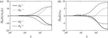
The four trans-helical helicity fluxes for the non-helical (a) and helical (b) cases:
 $\unicode[STIX]{x1D6F1}_{_{H}}^{++-}$
(solid line),
 $\unicode[STIX]{x1D6F1}_{_{H}}^{--+}$
(dotted line),
 $\unicode[STIX]{x1D6F1}_{_{H}}^{+--}$
(dashed line),
 $\unicode[STIX]{x1D6F1}_{_{H}}^{-++}$
(dash–dot line).

The trans-helical helicity fluxes for the non-helical (a) and helical (b) flow are shown in figure 7. The
 $\unicode[STIX]{x1D6F1}_{H}^{++-}$
flux is positive in the inertial range, and this implies that these interactions decrease
 $H^{+}$
. On the contrary,
 $\unicode[STIX]{x1D6F1}_{H}^{+--}$
is negative in the inertial range, implying an increase of
 $H^{+}$
in this range. For the non-helical flow, these effects balance each other, while, for the helical case, there is a dominance of the fluxes that involve interactions with more
 $u^{+}$
modes. The same conclusions can be drawn for
 $H^{-}$
and the fluxes
 $\unicode[STIX]{x1D6F1}_{H}^{--+}$
and
 $\unicode[STIX]{x1D6F1}_{H}^{-++}$
. In the limit
 $k\rightarrow \infty$
, both
 $\unicode[STIX]{x1D6F1}_{H}^{++-}$
and
 $\unicode[STIX]{x1D6F1}_{H}^{+--}$
are negative, implying net generation of
 $H^{+}$
, and the terms
 $\unicode[STIX]{x1D6F1}_{H}^{--+}$
and
 $\unicode[STIX]{x1D6F1}_{H}^{-++}$
are positive, implying net generation of
 $H^{-}$
. Thus, while there is no net generation of helicity, there is a net generation of both
 $H^{+}$
and
 $H^{-}$
, given by
 $$\begin{eqnarray}{\mathcal{G}}_{_{H}}=\lim _{k\rightarrow \infty }(\unicode[STIX]{x1D6F1}_{H}^{-++}+\unicode[STIX]{x1D6F1}_{H}^{--+})=-\lim _{k\rightarrow \infty }(\unicode[STIX]{x1D6F1}_{H}^{++-}+\unicode[STIX]{x1D6F1}_{H}^{+--})>0.\end{eqnarray}$$
This is true for both the helical and non-helical cases. This large generation of simultaneous
 $H^{+}$
and
 $H^{-}$
causes the fluxes shown in figure 6 to increase. It is also important to note here that, due to this generation, the individual dissipation rates
 $\unicode[STIX]{x1D716}_{_{H}}^{\pm }$
given by
 $\unicode[STIX]{x1D716}_{_{H}}^{\pm }\equiv \unicode[STIX]{x1D708}\langle \boldsymbol{w}^{\pm }\boldsymbol{\cdot }\unicode[STIX]{x1D735}\times \boldsymbol{w}^{\pm }\rangle$
are much larger (in absolute value) than the injection rate (and thus also the dissipation rate) of total helicity,
 $|\unicode[STIX]{x1D716}_{_{H}}|\ll |\unicode[STIX]{x1D716}_{_{H}}^{\pm }|$
. The two helicity dissipation rates
 $\unicode[STIX]{x1D716}_{_{H}}^{\pm }$
peak at the Kolmogorov dissipation length scale
 $\unicode[STIX]{x1D702}=1/k_{\unicode[STIX]{x1D702}}$
with
 $\unicode[STIX]{x1D716}_{_{H}}^{\pm }\propto \pm \unicode[STIX]{x1D716}_{_{E}}k_{\unicode[STIX]{x1D702}}$
. However, they have opposite signs and cancel each other to give a total dissipation rate of helicity
 $\unicode[STIX]{x1D716}_{_{H}}=\unicode[STIX]{x1D716}_{_{H}}^{+}+\unicode[STIX]{x1D716}_{_{H}}^{-}$
of much smaller amplitude. Equating
 $\unicode[STIX]{x1D716}_{_{H}}^{\pm }$
with
 $\unicode[STIX]{x1D716}_{_{H}}$
leads erroneously to a different dissipation length scale for the helicity which is not observed in the simulations (Ditlevsen & Giuliani Reference Ditlevsen and Giuliani2001a
,Reference Ditlevsen and Giuliani
b
; Chen et al.
Reference Chen, Chen and Eyink2003).
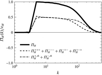
Total helicity flux
 $\unicode[STIX]{x1D6F1}_{_{H}}$
decomposed into
 $\unicode[STIX]{x1D6F1}_{_{H}}^{+++}+\unicode[STIX]{x1D6F1}_{_{H}}^{---}+\unicode[STIX]{x1D6F1}_{_{H}}^{+-+}+\unicode[STIX]{x1D6F1}_{_{H}}^{-+-}$
(dashed line) and
 $\unicode[STIX]{x1D6F1}_{_{H}}^{+,th}+\unicode[STIX]{x1D6F1}_{_{H}}^{-,th}$
(dash–dot line).

Despite the simultaneous generation of
 $H^{+}$
and
 $H^{-}$
, it turns out that the total helicity flux can also be decomposed into two fluxes that remain constant in the inertial range. This is demonstrated in figure 8, where the total helicity flux is plotted for the helical flow along with the symmetrized fluxes
 $\unicode[STIX]{x1D6F1}_{_{H}}^{+++}+\unicode[STIX]{x1D6F1}_{_{H}}^{---}+\unicode[STIX]{x1D6F1}_{_{H}}^{+-+}+\unicode[STIX]{x1D6F1}_{_{H}}^{-+-}$
and
 $\unicode[STIX]{x1D6F1}_{_{H}}^{+,th}+\unicode[STIX]{x1D6F1}_{_{H}}^{-,th}$
. It should be noted that for the helicity flux we need to add all conservative helical fluxes to obtain constant flux in the inertial range. Considering just
 $\unicode[STIX]{x1D6F1}_{_{H}}^{+++}+\unicode[STIX]{x1D6F1}_{_{H}}^{---}$
or just
 $\unicode[STIX]{x1D6F1}_{_{H}}^{+-+}+\unicode[STIX]{x1D6F1}_{_{H}}^{-+-}$
does not lead to a constant flux. We also note that adding these fluxes for the non-helical flow leads to zero flux, so it is not displayed. Again, this is not a trivial result. Conservation of helicity implies only that the total helicity flux is constant, and we could not a priori have concluded this result.
Implications of this result are discussed in the next section where conclusions are drawn.
5 Conclusions
In this work, the interactions between different helical Fourier modes were investigated with direct numerical simulations for large-Reynolds-number turbulent flows. By projecting the velocity field to the helical basis proposed in Craya (Reference Craya1958), Lesieur (Reference Lesieur1972) and Herring (Reference Herring1974), a decomposition of the energy and helicity fluxes was derived which allowed the roles of interactions among modes of different helicities to be investigated separately. In this formalism, eight partial energy fluxes and eight partial helicity fluxes were defined which measure the rate (for nonlinear interactions of a particular type) of transfer of energy and helicity from a given spherical set of Fourier modes. The proposed formalism was then applied to the results of large-resolution numerical simulations. Two flows were considered, one without mean helicity and one that was positively helical. For these flows, the partial fluxes were explicitly calculated at steady state. The results are very intriguing.
As shown in figure 3, the partial energy fluxes defined can be grouped together so that the total flux can be decomposed into three fluxes that are independently constant in the inertial range. This is a non-trivial result since it cannot be derived from energy conservation alone which implies constancy of only the total energy flux. Furthermore, the relative amplitude of these fluxes is the same for both the helical and the non-helical flow, and thus these fractions are possibly universal. In particular, the fluxes that correspond to same-helicity interactions are negative at all scales, implying the presence of an inverse cascade of energy, which coexists with but is overwhelmed by the forward cascade due to the remaining interactions. The helicity flux, shown in figure 8, can also be decomposed into two fluxes that are independently constant in the inertial range, and are both positive. The existence of constant-energy and -helicity partial fluxes in the inertial range possibly implies the existence of additional Kármán–Howarth (de Karman & Howarth Reference de Karman and Howarth1938) relations for the real vector fields
 $\boldsymbol{u}^{+}$
and
 $\boldsymbol{u}^{-}$
.
Furthermore, the present results shed some light on how parity invariance is restored in the small scales. From the four partial fluxes
 $\unicode[STIX]{x1D6F1}_{_{E}}^{s,-s,s_{3}}$
that exchange energy between
 $E^{+}$
and
 $E^{-}$
, the two
 $\unicode[STIX]{x1D6F1}_{_{E}}^{s,-s,+}$
tend to transfer energy from
 $E^{+}$
to
 $E^{-}$
, while the other two
 $\unicode[STIX]{x1D6F1}_{_{E}}^{s,-s,-}$
transfer energy inversely from
 $E^{-}$
to
 $E^{+}$
. In the presence of an imbalance between
 $E^{+}$
and
 $E^{-}$
(say, for example,
 $E^{+}\gg E^{-}$
), the fluxes involving two positively helical modes are greater than the ones involving only one positive helical mode. Thus, the flux
 $\unicode[STIX]{x1D6F1}_{_{E}}^{s,-s,+}$
that transfers energy to
 $E^{-}$
overcomes the oppositely directed flux
 $\unicode[STIX]{x1D6F1}_{_{E}}^{s,-s,-}$
, and
 $E^{+}$
and
 $E^{-}$
become asymptotically equal at small scales.
The present results also have various implications for future investigations both practical and also theoretical. First of all, they provide a means to test some of the assumptions made in small-scale turbulence models. The presence of a ‘hidden’ inverse cascade (expressed by the negative fluxes of energy
 $\unicode[STIX]{x1D6F1}_{E}^{+++}$
and
 $\unicode[STIX]{x1D6F1}_{E}^{---}$
) implies that there is information from the small scales that travels back to the large scales. The traditional point of view of classical small-scale modelling (Smagorinsky Reference Smagorinsky1963) assumes that the small-scale turbulent motions act only as a sink of turbulent energy, transferring it to even smaller scales, and thus they are typically modelled as an eddy dissipation term. This type of modelling was realized early on to lead to erroneous results due to the absence of an energy feedback of the unresolved scales to the resolved scales, often referred to as a ‘backscatter’ of energy (Piomelli et al.
Reference Piomelli, Cabot, Moin and Lee1991; Menon, Yeung & Kim Reference Menon, Yeung and Kim1996). More sophisticated models that take this effect into account by stochastic modelling (Leith Reference Leith1990; Schumann Reference Schumann1995), EDQNM closures (Baerenzung et al.
Reference Baerenzung, Politano, Ponty and Pouquet2008, Reference Baerenzung, Mininni, Pouquet and Rosenberg2011) or Lagrangian averaging (Meneveau, Lund & Cabot Reference Meneveau, Lund and Cabot1996; Chen et al.
Reference Chen, Foias, Holm, Olson, Titi and Wynne1998, Reference Chen, Holm, Margolin and Zhang1999) have been devised. The present work gives a physical mechanism for this backscatter effect and provides a quantitative way to test current models so that they can properly capture the feedback effect of small scales to large.
Second, this investigation indicates how scales larger than the forcing scale reach an equilibrium. At scales larger than the forcing scale, the averaged energy flux is zero, so it is assumed that these scales reach a thermal equilibrium (Kraichnan Reference Kraichnan1973) where energy is equally distributed among modes with no net exchange of energy. However, recent results have shown that the largest scales in the domain deviate from this equilibrium, exhibiting much larger energy (Dallas, Fauve & Alexakis Reference Dallas, Fauve and Alexakis2015). The present results indicate that the injection energy from the small scales driven by the
 $\unicode[STIX]{x1D6F1}^{s,s,s}$
fluxes is balanced by the removal of energy from the remaining fluxes. There are thus two distinct processes that add and remove energy from the large scales. This process might shed light on the deviations observed in the large-scale energy spectrum from the isothermal equilibrium. Such investigation would, however, require simulations forced at scales small enough so that there is scale separation.
Finally, we would like to enrich the set of numerical experiments proposed in Biferale et al. (Reference Biferale, Musacchio and Toschi2013) of modified versions of the Navier–Stokes equation by considering the following generalized Navier–Stokes equation:
 $$\begin{eqnarray}\unicode[STIX]{x2202}_{t}\boldsymbol{u}^{s_{1}}=\mathop{\sum }_{s_{2},s_{3}}\unicode[STIX]{x1D736}^{s_{1},s_{2},s_{3}}\mathbb{P}^{s_{1}}\left[\boldsymbol{u}^{s_{2}}\times \boldsymbol{w}^{s_{3}}\right]+\unicode[STIX]{x1D708}\unicode[STIX]{x0394}\boldsymbol{u}^{s_{1}}+\mathbb{P}^{s_{1}}[\boldsymbol{F}],\end{eqnarray}$$
where
 $\unicode[STIX]{x1D736}^{s_{1},s_{2},s_{3}}$
is a real
 $2\times 2\times 2$
matrix. One can then consider continuous variations of
 $\unicode[STIX]{x1D6FC}^{s_{1},s_{2},s_{3}}$
starting from the Navier–Stokes equation obtained for
 $\unicode[STIX]{x1D6FC}^{s_{1},s_{2},s_{3}}=1$
to different possible limits. For example, one can consider the case where the two energies
 $E^{\pm }$
are conserved independently but not the helicity (for
 $\unicode[STIX]{x1D6FC}^{s,-s,s_{3}}=0$
and the remaining values of
 $\unicode[STIX]{x1D6FC}^{s_{1},s_{2},s_{3}}$
equal to unity) or the case for which the two helicities
 $H^{\pm }$
are conserved but not the total energy (for
 $\unicode[STIX]{x1D6FC}^{s,s_{2},-s}=0$
and the remaining values of
 $\unicode[STIX]{x1D6FC}^{s_{1},s_{2},s_{3}}$
equal to unity). Of particular interest is the case for which
 $\unicode[STIX]{x1D6FC}^{s_{1},s_{2},s_{3}}=\unicode[STIX]{x1D706}$
for all values of
 $s_{i}$
except when
 $s_{1}=s_{2}=s_{3}$
, for which
 $\unicode[STIX]{x1D6FC}^{s,s,s}=1$
. Then, for
 $\unicode[STIX]{x1D706}=1$
, one obtains the Navier–Stokes equation, while for
 $\unicode[STIX]{x1D706}=0$
, the system (5.1) reduces to the system studied in Biferale et al. (Reference Biferale, Musacchio and Toschi2013), where
 $E^{\pm }$
and
 $H^{\pm }$
are conserved independently and an inverse cascade is observed. One could thus continuously transition, varying
 $\unicode[STIX]{x1D706}$
from a system that cascades energy forward to a system that cascades energy inversely. Such systems are known to exhibit critical transitions (Celani, Musacchio & Vincenzi Reference Celani, Musacchio and Vincenzi2010; Deusebio et al.
Reference Deusebio, Boffetta, Lindborg and Musacchio2014; Seshasayanan, Benavides & Alexakis Reference Seshasayanan, Benavides and Alexakis2014; Sozza et al.
Reference Sozza, Boffetta, Muratore-Ginanneschi and Musacchio2015; Seshasayanan & Alexakis Reference Seshasayanan and Alexakis2016). If this is the case, it can open new ways for exploring the Navier–Stokes turbulence as an out-of-equilibrium system close to criticality.
Acknowledgements
The author is grateful to P. Ditlevsen, L. Biferale, R. Stepanov and F. Plunian as well as three anonymous referees for their useful comments and references which they provided me with for this work. I would also like to thank S. J. Benavides for proofreading the manuscript. This work was granted access to the HPC resources of MesoPSL financed by the Region Ile de France and the project Equip@Meso (reference ANR-10-EQPX-29-01) of the programme Investissements d’Avenir supervised by the Agence Nationale pour la Recherche and the HPC resources of GENCI-TGCC-CURIE and GENCI-CINES-OCCIGEN (Project Nos x2015056421 and x2016056421) where the present numerical simulations were performed.