

Since their initial discovery 40 years ago, the earthworks of Tikal, Guatemala, have played an important role in our understanding of patterns of demography, settlement, and militarism at Tikal and in the Maya Lowlands in general. Our recent study of the earthworks has added significant new data, some of which contradicts well-established interpretations concerning the form and defensive function of the earthworks (Webster, Silverstein, Murtha, Martinez, and Straight Reference Webster, Murtha, Straight, Silverstein, Martinez, Terry and Burnett2007). Rather than supporting established conclusions about the Maya construction, our current research shows that the feature could not have effectively fulfilled the well-accepted role of a defensive boundary for the hinterlands of Tikal and that the primary function of the feature remains elusive.
Water posed an enormous challenge to Tikal's sociopolitical evolution and maintenance, but hydraulic functions for the earthworks have previously been dismissed based on the porous nature of the limestone bedrock through which water would quickly infiltrate into the subsurface and because the frequent changes in elevation would make a continuous flow along the length of the earthworks impossible (Puleston and Callender Reference Puleston and Callender1967; contra Scarborough Reference Scarborough2003:80). Keeping in mind that rainfall served as the primary source of water for the polity, we believe that the possibility that the earthworks were in fact constructed for a hydraulic purpose must be reconsidered. We propose that the earthworks might have functioned as a limestone filtration trench built to collect subsurface water in support of lowland agriculture by mitigating risk factors associated with wet season canicular droughts or making possible a late season planting.
BACKGROUND
The late twentieth century saw a dramatic transformation in our understanding of Maya civilization. Despite the discovery of militaristic depictions on murals, stelae, and lintels, the idea that the Maya were loosely organized along the lines of a largely peaceful confederation of civic-ceremonial centers persisted throughout the early twentieth century. The discovery of an impressive earthwork guarding the northern approaches to Tikal in 1966 heralded the demise of the “peaceful Maya” interpretation. The earthwork was found during the University of Pennsylvania Sustaining Area Project directed by Dennis Puleston (Reference Puleston1973, Reference Puleston1983). Based on their investigation, Puleston and Donald Callender (Reference Puleston and Callender1967) proposed a model of the earthwork as a defensive barrier and hinterland boundary that has endured for 40 years.
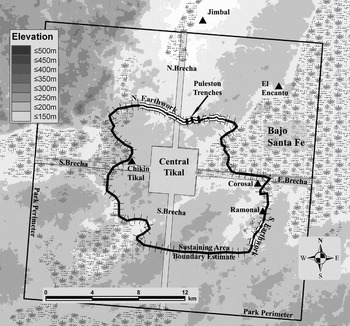
Puleston and Calendar first encountered the earthwork 4.5 km north of the central acropolis of Tikal. Using compass and pace, they mapped a 9.6 km long segment of the earthwork running east-west, and with the help of a local guide, they identified a separate earthwork segment approximately 1 km long, running northeast-southwest some 8.25 km southeast of the central acropolis. Their investigation also included the excavation of three trenches to examine the morphology of the ditch and embankment. One trench was placed across one of the numerous gaps that occurred where the ditch seemed to disappear as it traversed one of the many lowland bajos that dot the countryside, another was dug in an area where it appeared that there was a bridge or causeway across the earthwork, and the third was excavated through a well-preserved section of the earthwork (Figure 1).
The map of the sustaining area of Tikal and the exploratory trenches excavated by Puleston (modified from Puleston Reference Puleston1983:Figure 1).

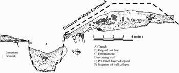
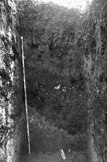
Each of the excavations addressed specific questions about the earthwork. The trench in the well-preserved segment revealed the local morphology of the ditch and inner embankment, which became thereafter the standardized model for the earthwork as a whole. The ditch, approximately 3.5 m wide and 3.1 m deep, was backed by an embankment approximately 2 m high and 4 m wide constructed by piling up the excavated limestone spoil along the southern edge (Figure 2). There was speculation that a wooden palisade once extended across the crest of the embankment, but no post molds were found. The excavation at the causeway showed that there were intentional gaps in the embankment and a corresponding causeway across the ditch. The causeway itself was narrow, only 1.5 m wide, and it was constructed with cut stones, rubble, and layers of plaster. In the bajo, Puleston and Callender found stains deep in the bajo clay suggesting that the earthwork had continued across the apparent gaps. Unfortunately, seasonal saturation of the argillic soils caused their trench to collapse before it could be well-documented (Puleston and Callender Reference Puleston and Callender1967).
Puleston and Callender's profile of the easternmost trench that became the template of what the earthwork should look like (modified from Puleston and Callender Reference Puleston and Callender1967:Figure 2).

Puleston's exploration of the earthwork yielded a few ceramic artifacts that shed some light on the role of the earthwork and its periods of use. The most significant cache of ceramics was recovered alongside the bridge. The ceramic complexes recovered there ranged from Manik to Imix times (250–850 a.d.), with the majority of the sherds from the Ik complex (600–700 a.d.) (Fry Reference Fry1969:85). An assortment of lithic and ground stone objects as well as large quantities of decorated wares were recovered, conjuring up images of traders with their wares funneled across the bridge to enter the realm of Tikal (Puleston and Callender Reference Puleston and Callender1967:45). The chronology of the construction proved to be elusive, with only a single diagnostic sherd found under the embankment that could be used for a coarse estimate of a terminus post quem. The sherd was from a basal flange bowl of the Manik complex dating to 250–550 a.d., leading to an Early Classic period estimate for the construction of the earthwork, or at least that portion of it (Fry Reference Fry1969; Puleston and Callender Reference Puleston and Callender1967:43; see Webster et al. Reference Webster, Silverstein, Murtha, Martinez and Straight2004:22–28). Puleston and Callendar recognized how weak this evidence was, but an Early Classic period date in the mid-sixth century nevertheless became the default assumption in the later literature.
Although no work was done on the “southern” earthwork, Puleston concluded that the earthwork consisted of a pair of parallel walls guarding the north and south limits of the hinterlands of Tikal. The defensive walls were anchored on the Sante Fe bajo on the east and another large logwood bajo on the west, and they enclosed roughly 120 km2. This region, which Puleston called “Residential Tikal,” became the accepted territory of the polity at the end of the Early Classic period (Culbert et al. Reference Culbert, Kosakowsky, Fry, Haviland, Culbert and Rice1990; Haviland Reference Haviland and Sabloff2003; Puleston Reference Puleston1983). Most subsequent population estimates for the polity derived from estimates of structures within this perimeter. The Great Earthwork of Tikal also became a keystone in our assumptions about interpolity conflict in the Maya Lowlands, suggesting not only warfare, but warfare on an impressive scale.
Even though the earthworks were enthusiastically integrated into the body of literature on Tikal and the Maya, they were largely ignored archaeologically after the University of Pennsylvania project until 2001, with the initiation of a project to reevaluate them (Webster et al. Reference Webster, Silverstein, Murtha, Martinez and Straight2004). The only other investigation that reexamined any portion of the earthwork was Annabel Ford's survey transect between Tikal and Yaxha (Ford Reference Ford1981, Reference Ford1986), during which she mapped a portion of the southeast section identified by Puleston. The model for the earthwork as proposed by Puleston became the accepted, if unverified, interpretation of the earthwork, which is described as a hinterland defense or “city wall” in almost every major publication discussing the territorial organization of Tikal. This interpretation was consistent with the available data and congruent with the reinterpretation of the Classic period Maya from a peaceful Maya civilization to one dominated by endemic internecine warfare.
STUDIES SINCE 2003
Our recent research on the earthworks ran from 2003 to 2006 and consisted of a resurvey of the northern earthwork and extended explorations beyond the termini originally found in 1966, as well as explorations in the west and southeast to search for additional sections. We also conducted settlement surveys extending 125 m north and south of the northern earthwork and several block surveys. All told, we mapped 7 km2 of settlement with 113 mound groups and 474 structures (Webster, Silverstein, Murtha, Martinez, and Straight Reference Webster, Silverstein, Murtha, Martinez, Straight and Cobean2007). These new data brought into question some of the important underlying assumptions about the extent and form, and consequently the function, of the Tikal earthworks.
In the north, we found an additional western extension to the original line of earthworks on the far side of an 800 m wide bajo where Puleston and Callender had lost the line of the ditch. At one point, there is a bifurcation where a branch of earthwork turns north and terminates after 300 m in a small reservoir or aguada called El Duende. El Duende is largely filled-in but still has some limited function as a water source for poachers and looters as evidenced by the plastic water containers found scattered around it. Although the aguada is similar to those usually found near plaza groups, it is on the edge of a bajo and there are no visible structures in its immediate vicinity. The other branch of the earthwork runs uphill to the southwest where, after an additional distance of 2.25 km, it fades into a logwood bajo as originally envisioned by Puleston and Callender. The earthwork was again located on the far southwest side of the logwood bajo where, with gaps, it runs in a southwesterly direction, extending some 800 m beyond the western boundary trail of the Tikal National Park in the direction of Lake Peten Itza (17 km away from the last known segment of the earthwork).
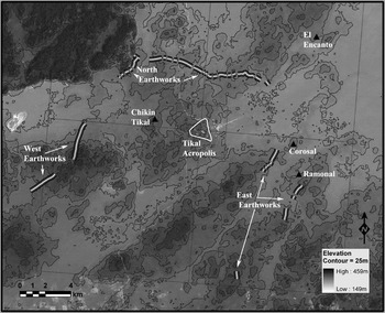
In the south, we found no trace of the earthwork that had been presumed to parallel the northern one. In fact, the additional segments of earthwork encountered southeast of the epicenter run parallel to each other rather than in tandem (Figure 3). In total, our study mapped approximately 24.6 km of earthwork (disregarding gaps of less than 1 km), including the remapping of the original 9.6 km in the north and 1 km in the southeast.
The map of all known earthworks generated during the EFAT. Parallel and isolated segments are labeled A, B, and C (Webster, Silverstein, Murtha, Martinez, and Straight Reference Webster, Brook, Railsback, Cheng, Edwards, Alexander and Reeder2007).

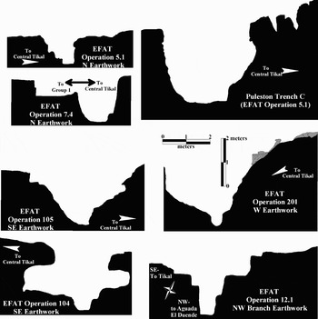
Although the newly mapped earthwork segments show no evidence for the existence of a continuous southern boundary, the north, and to a lesser degree, the west segments remain consistent in dimension with the defensive purpose originally proposed. Our doubts about the military function derive not only from the perimeter arrangement of earthwork segments that do not conform to Puleston's defensive hypothesis, but also from the topographical placement and form of some segments, as well as the assertion that the large bajos adequately served as barriers. The majority of the earthwork runs along slopes rather than up on the crests, thereby sacrificing much of their potential tactical advantage. In a few cases, the facing hillslope actually would favor an attacking enemy. Nor is the earthwork uniform in scale or configuration. One segment that was trenched where the earthwork appeared to be little more than a low swale exposed a ditch that was only about 1.7 m wide and 1.7 m deep, with a proportionately small embankment on the south lip (Figure 4:Operation 5.1). Clearly this segment is militarily inconsequential. It is located due north of the acropolis in a sector that would be of primary strategic importance to a linear fortified wall. Either this important section of the earthwork was never completed or it was built for a purpose other than defense. An excavation where the earthwork articulated with the south side of Group 1 (Figure 4:Operation 7.4) showed it to be 2.25 m deep and only 1.6 m wide, again a width easily leaped by an attacker. On the unexcavated south side of that portion of the ditch, there was only the slightest indication of an embankment, little more than a raised walkway. It is possible that spoil from the ditch was used for lime in construction or in maintenance of the adjacent plaza group rather than construction of an embankment. On the north edge of the ditch, the bedrock had been carved with a small lip on the edge, creating a shallow landing with steps carved on the west side leading up toward the group. Approximately 10 m north of the ditch lay one of the three aguadas associated with the multi-plaza group, but no direct articulation between the aguada and ditch was found. Finally, the survey teams traversed several bajos and came to the universal opinion that, although inhospitable because of thorny vegetation, the dry season bajos could easily be passed by determined attackers. This theory assumes that ancient environmental conditions were reasonably similar to today's conditions.
Scale profiles of trench cross sections of the earthworks in the north, west, and southeast.

Our preliminary assessment of the earthwork was able to throw into question the following established assumptions (Webster, Silverstein, Murtha, Martinez, and Straight Reference Webster, Silverstein, Murtha, Martinez, Straight and Cobean2007:61):
1. The earthworks represent fortifications (or at least finished ones).
2. There is a southern earthwork; someone might discover one someday, but until then the “southern earthwork” is an archaeological will-o'-the-wisp.
3. The earthworks were built in Early Classic period times, or they can be associated with events in Tikal's culture history as reconstructed from art and epigraphy.
4. The earthworks affected the distribution and density of settlement at any particular time, and especially during the eighth and ninth centuries a.d., which are featured in most reconstructions.
5. The oft-cited 120 km2 core polity as envisioned by Puleston existed.
6. The 120 km2 zone has value beyond that of an arbitrary heuristic border in making demographic estimates and characterizing Tikal as a center, “city,” agricultural hinterland, or polity.
HYDRAULIC HYPOTHESIS
Precipitation, Hydrology, and Anthropogenic Intervention
In environments where water is scarce, development of hydrologic resources is necessary for the intensification of agriculture, population growth, and the evolution of sociopolitical complexity (Bosserup 1965; Hayashida Reference Hayashida2006; Wittfogel Reference Wittfogel1957). In the Tikal region, surface water is patchy and in many places naturally accessible only during the wet season. More than 80% of the annual rainfall (1,350–2,000 mm) falls between May and November (Gallopin Reference Gallopin1990:11; Puleston Reference Puleston1973:241–246). A stark reminder of the difficulty of obtaining water can be seen as one drives through the town of Zocotzal at the entrance to the national park during the dry season. Every household has an assortment of containers and barrels set out along the road waiting for distribution from the government water truck. The Tikal National Park also depends on trucked-in water. Seasonal shortage of water has led Ford (Reference Ford and Fedick1996), Lucero (Reference Lucero2006), and Scarborough (Reference Scarborough1998, Reference Scarborough2003) to propose that control of hydraulic projects played an important role in the consolidation and maintenance of sociopolitical power at Tikal.
Lacking riparian resources, the Classic period Maya of Tikal had to find a way to manipulate the most dependable water source available: precipitation. On the acropolis, the correlation of massive architecture with sloped plazas and drainage ditches designed to fill the empty quarries turned reservoirs is striking. Scarborough and Gallopin (Reference Scarborough and Gallopin1991:23–45) estimated that the 62-ha area of Tikal's central acropolis could direct an annual flow of 900,000 m3 of rain runoff that could fill the 100,000–250,000 m3 capacity of the six central reservoirs as well as the bajos that flank the acropolis (Scarborough Reference Scarborough2003:51; Scarborough and Gallopin Reference Scarborough and Gallopin1991; see Carr and Hazard Reference Carr and Hazard1961:12–15). The work of Gallopin, Scarborough, and Lucero suggests that the ability to harvest precipitation might substitute for perennial sources of water commonly associated with the evolution of sociopolitical complexity elsewhere in the world (Scarborough Reference Scarborough, Lucero and Fash2006).
Even though a basic model for the hydraulic works at the acropolis has been proposed (Gallopin Reference Gallopin1990:23–45), the hinterlands of Tikal are sorely lacking in hydrologic assessment. Puleston's survey found many aguadas in direct association with groups of structures in the hinterlands of Tikal. Like miniature models of the acropolis, the group aguadas are generally situated to take advantage of runoff from plazas and natural drainages. Larger aguadas frequently have visible spillways from their downslope sides that must have been used for some sort of water redistribution or overflow control system (Puleston Reference Puleston1973:92, 97–98). Notwithstanding the sample bias against invisible structures in surface survey, settlement studies at Tikal (Bronson Reference Bronson1966; Haviland Reference Haviland and Sabloff2003; Olson Reference Olson1977:10; Puleston Reference Puleston1973, Reference Puleston1983) show that plaza groups are generally situated on high ground. If, as has been suggested, Maya agricultural intensification was predicated on vertical expansion, taking advantage of high and lowland strategies, corporate constructions aimed at exploitation of the full range of usable environs would be expected (Hammond Reference Hammond, Harrison and Turner1978; see discussion by Scarborough [2006] on convex watersheds). Although no evidence of agricultural terracing of upland slopes (which are generally modest) has been found at Tikal, it may be that the earthworks and some aguadas are examples of communal lowland exploitation strategies (for bajo exploitation history, see Dunning et al. Reference Dunning, Beach, Luzzadder-Beach, Lucero and Fash2006).
One of the zones in the Tikal Park with the least access to perennial surface water is the sector 4–5 km north of the acropolis. Although lacking the larger nucleated settlements such as Ramonal and Chalpate in the southeast, Chikin Tikal in the west, and Jimbal or El Encanto farther north, the northern population density does not appear to otherwise suffer (Puleston Reference Puleston1973, Reference Puleston1983). If we assume that ancient rainfall levels and patterns were similar to those of modern times, dependence on unmodified rainfall and drainage patterns would have made local agriculture generally risky. Such risk was compounded because of a hiatus in the rainy season that occurs sometime between mid-June and early August (Hester Reference Hester1954; Puleston Reference Puleston1973). Exceptional droughts also putatively occurred in the sixth and eighth through tenth centuries a.d. (Gill Reference Gill2000; see also Peterson and Haug Reference Peterson and Haug2005).
The canicula, or veranillo, is a meteorological phenomenon that causes a short drought related to the period when the solar altitude approaches 90° over the Maya region (roughly 15° to 21° N latitude [ca. June 7]) (Puleston Reference Puleston1973:245). The duration and dates of the canicula are variable and the impact of a prolonged canicula on agriculture could be severe (Dahlin et al. Reference Dahlin, Beach, Luzzadder-Beach, Hixson, Hutson, Manoni, Mansell and Mazeau2005:234–235). Hester (Reference Hester1954:27–28) reported a canicular drought in the town of Telchaquillo, Yucatan, in 1953, that affected approximately 90% of the farmers who lost 80% of their maize crops. Considering the potential impact of a protracted canicular drought on crops, it seems likely that the Maya would have developed mechanisms for mitigating the risk.
Various techniques to support agricultural intensification and mitigate risk factors were known to the Maya in the Classic period (Lucero and Fash Reference Lucero and Fash2006). Terracing (Beach et al. Reference Beach, Luzzadder-Beach, Dunning, Hageman and Lohse2002; O'Mansky and Dunning Reference O'Mansky, Dunning, Demarest, Rice and Rice2004) was used extensively at numerous sites including Caracol (Healy et al. Reference Healy, Lambert, Arnason and Hebda1983; Murtha Reference Murtha2002). At Kaminaljuyu, Palenque, and other sites, canals were constructed to distribute water (Barrientos Reference Barrientos Q., Laporte and Escobedo1996; French Reference French and Marken2007; Valdes Reference Valdes, Lucero and Fash2006). At Copan, Davis-Salazar (Reference Davis-Salazar2003) suggested that there may have been communal control of domestic lagoons (contra Weis-Krejci and Sabbas Reference Weis-Krejci and Sabbas2002), and wetland drained-field agriculture has been postulated for various sites (Dunning et al. Reference Dunning, Luzzadder-Beach, Beach, Jones, Scarborough and Culbert2002; Dunning et al. Reference Dunning, Beach, Luzzadder-Beach, Lucero and Fash2006; Fedick et al. Reference Fedick, Morrison, Andersen, Boucher, Acosta and Mathews2000; Pohl Reference Pohl1990; Pope and Dahlin Reference Pope and Dahlin1989; Scarborough Reference Scarborough1983, Reference Scarborough and Fedick1996). It has also been proposed that some wetlands in the Peten (e.g., El Bajo La Justa and El Bajo Santa Fe) were developed with elaborate water transport systems used in conjunction with wetland exploitation (Culbert et al. Reference Culbert, Fialko, McKee, Grazioso, Kunen, Paez, Laporte and Escobedo1996; Fialko Reference Fialko, Laporte and Escobedo1999; Grazioso et al. Reference Grazioso, Culbert, Fialko, Sever, Murphy, Ramos, Laporte, Suasnávar and Arroyo2000).
The original low intensity swidden model of Maya agriculture has been widely challenged by the proposition that large nucleated populations could not have been supported by swidden agriculture alone (Harrison and Turner Reference Harrison and Turner1978; Puleston Reference Puleston1973:207). New data, much of it collected by satellite (Pope and Dahlin Reference Pope and Dahlin1989), suggest that Maya subsistence strategies varied widely across the Maya culture area according to their particular environmental circumstances (see Pohl and Miksicek Reference Pohl, Miksicek and Pohl1985). Still, arguments that the population of Tikal during the Classic period could not have been supported by a long fallow system are challenged by basic productivity models (Webster, Silverstein, Murtha, Martinez, and Straight Reference Webster, Silverstein, Murtha, Martinez, Straight and Cobean2007). The Maya Lowlands are far from being geologically or hydrologically uniform (West Reference West, Wauchope and West1964), and the Maya appear to have been adept at adapting their agricultural practices to optimize the available lands and resources.
During the rainy season, Maya householders depended on sloped plazas, drains, reservoirs, and probably roof runoff to collect and store sufficient water to meet their domestic needs for the year. A hydraulic model for the earthwork presupposes that the need for collection of surplus water extended beyond needs of domestic use, and that, at least in certain regions of the polity, additional collection methods were required to augment agricultural production. Boserup's (Reference Boserup1965) analysis of the relationship of labor and agricultural intensification suggests that Maya farmers, under duress from demographic pressure, would have increased labor input and sought innovations to enhance production. Yet, Webster, Silverstein, Murtha, Martinez, and Straight (Reference Webster, Silverstein, Murtha, Martinez, Straight and Cobean2007) argued that there is insufficient evidence to presume sufficient population pressure at Tikal to stimulate intensive modifications to the landscape. They estimate that the carrying capacity for Tikal, based on a hinterland area of 120–200 km2 (following the now equivocal assumption that the old model of the earthworks corresponds roughly to a territorial boundary), would have had an Early Classic period population of 15,000–30,000, which could have sustained itself using nonintensive long fallow rotation farming given the available land.
Such arguments do not negate the possibility of engineered constructions that would have intensified production. First, our population estimates, as well as the territorial extent of Tikal at any particular time, are coarse, with a low confidence interval and a high range of error. Second, population pressure could be a localized phenomena caused by the nucleation of settlements in response to other sociopolitical forces that are lost in macro-regional population estimates. Third, agricultural intensification could occur without substantial demographic pressure for a variety of reasons including management of environmental risk, a response to external pressures such as taxation or market opportunities, as a response to soil degradation, to compensate for land loss to competing groups, or the convenience of using immediately adjacent land. Furthermore, intensification tends to carry connotations of punctuated radical revolutions in farming efficiency such as raised fields, whereas incremental graduated development seems more likely. Limited advantages can be gained by the exploitation of lands that would otherwise be unused or as a means for farmers to spread their labor throughout the year rather than being constrained to benefiting from labor input only during the prime growing season.
Examples of intensification sans demographic pressure abound. For instance, drained-field horticulture using drainage canals called barets in Papua New Guinea appear as early as 9,000 years ago, at a time when it is unlikely that there was significant demographic pressure (Denham Reference Denham2003; Herman Mandui, personal communication 2007). In the Peten, the population in the municipios surrounding Lake Peten Itza in 1958 was approximately 10,000, and the 1950 population of the entire Department of the Peten was approximately 20,362 (estimated from the 1950 census in Cowgill Reference Cowgill1961:12). Of the 3,585,400 ha of land in the Peten, only 6,193.3 ha were under cultivation in 1950. Even if the uncounted population doubled the census numbers, the population obviously falls far below carrying capacity. Even though farming in the Peten was based on swidden agriculture, farmers still varied their planting strategies, using different types of land and planting at different times of the year to mitigate risks and distribute labor. If demographic pressure limited available land, as it must have by the Late Classic period if not earlier, then a likely response would have focused on increasing the productivity of marginal agricultural lands.
Karst Hydrography
According to the wise, one of the things most needed by man is water, without which the earth cannot produce its fruits or man live.… In this respect nature has acted differently in this country from the rest of the world, where the rivers and springs flow above ground, whereas here all run in secret channels underground. (Landa Reference Landa and Gates1978:94–95 [1562])
Although Landa's 1562 comments refer specifically to northern Yucatan, his observation holds true for the seasonally dry Peten as well, the difference being that the caves and cenotes that occur with remarkable frequency in the younger karst bedrock nearer the Gulf of Mexico occur infrequently in the older karst of the Tikal region (Dunning et al. Reference Dunning, Beach, Luzzadder-Beach, Lucero and Fash2006; West Reference West, Wauchope and West1964:72–73). Puleston (Reference Puleston1973:234) noted, “in contrast to more northern portions of the peninsula, the region around Tikal cannot be considered to be typically karsted in the way the north is.” During his survey, Puleston did find sinkholes south and west of the acropolis, but described these resumideros as drain point dolines in which, in one example, water could be seen whirlpooling down during heavy rains. This same doline had no surface water during the dry season. Dolines can account for only a small fraction of the substantial surface water generated during the rainy season. Most of the water does not find direct passage underground nor, with the exception of the large arroyos southeast and south of the epicenter, does it follow a fluvial surface regression, but instead infiltrates through the thin soils and percolates into the limestone bedrock. In much of the Tikal polity's landscape, particularly north of the acropolis, the soils, bedrock, and topography do not support large amounts of runoff (White Reference White1988:107–109).
With regard to the acropolis, Carr and Hazard (Reference Carr and Hazard1961:13–15) noted “that although there is relatively little surface drainage today even in the rainy season, there are many well-defined drainages, and even sharp gullies and ravines.” Over three seasons of fieldwork in the area of the northern earthwork, we observed little evidence of significant natural surface flow down the hillslopes, except in the far northwest corner where the hills rise sharply. Broad arroyos are present in the shallow valleys and bajos that lie between the low undulating hills, but these do not appear to have been formed by tributaries that would otherwise cut through the topsoil and limestone bedrock if there was significant flow volume. Surface flow is based on the amount (intensity and duration) of precipitation, the grade of the slopes that define a watershed, the rates of evapotranspiration, infiltration, and percolation, as well as the area of catchment above a slope, throughflow, and soil piping (Carson and Kikby Reference Carson and Kirkby1972; White Reference White1988:149–172). In much of the Tikal National Park, the low hills and the porosity and permeability of the soil and bedrock are not conducive to significant surface flow, at least as viewed now after a thousand years of minimal anthropogenic influence.
The slopes and ridge tops of Tikal are covered with a shallow layer of humus and silty clay loam. In a test pit placed purposefully in what appeared to be a culturally sterile locale near the north earthwork (Operation 8.1), the depth to bedrock was approximately 37 cm below surface, and the 60 test pits dug in and around sites during our study almost never reached a depth of 1 m, and were usually much shallower (see Webster et al. Reference Webster, Silverstein, Murtha, Martinez and Straight2004). This thin layer of topsoil is consistent with the depths observed by Puleston (Reference Puleston1973) in the hinterland, and by Olson (Reference Olson1977) in the upland areas in and around the acropolis. The lower-lying parts of the landscape have increasingly thicker and denser topsoils culminating in bajos with several meters of dense Vertisols. The bedrock exposed in the ditch cut consists of a relatively hard cap of leached caliche limestone approximately 1 m thick that overlies soft chalky limestone sascab (Puleston Reference Puleston1973:256–258). The geomorphic character of Tikal's bedrock is a hydrophilic, mildly karsted limestone that falls on the far end of the hydraulic conductivity scale (White Reference White1988:152–174).
THE EARTHWORK AS HYDRAULIC CONSTRUCTION
The problem facing the Maya of Tikal was how to maximize the collection and storage of water given a hydrologic system in which the primary source, precipitation, readily infiltrated into the earth. The hydrographic constraints that the Maya had to work within included an unconfined karst water table (e.g., the water percolated into an open system without artesian springs or flowing wells), dramatic seasonal variation in rainfall with a variable canicula in the midst of the growing season, porous bedrock that could absorb a high volume of water, permeable bedrock allowing significant subsurface movement of the water, and bajos with less permeable hydromorphic soils. Under the natural regimen, precipitation would infiltrate down toward the phreatic or saturation zone. During the rainy season, the saturation zone would rise to a level that would inundate the Vertisols of the bajos, resulting in some surface flow and accumulation over the less permeable argillic soils (Richard Terry, personal communication 2006). Furthermore, the water table tends to follow the topography, rising to follow the contours of the hills and thereby creating a meniscus-like effect occurring in conjunction with the elevation of the hills (White Reference White1988:153–155). The tendency for the water table to follow the contours of the surface has been exploited by numerous cultures from Persia (qanats) to South America (puquios) (Beekman et al. Reference Beekman, Weigand and Print1999; Schreiber and Lancho Rojas Reference Schreiber and Rojas1995, Reference Schreiber and Rojas2003). Archaeological data suggest that this principle was also exploited by the Maya of the Classic period.
Kevin Johnston (Reference Johnston2004) summarized four distinct types of wells used in the Maya region: (1) fault line spring exploitation wells (at Itzan and the Rio de la Pasion drainage system and the Three Rivers/Rio Hondo region), (2) stone or ceramic-lined wells that expose perched water tables (Dzibilchaltun, Quirigua, and Margarita Maza), (3) chenes wells that capture bedrock infiltration (Chenes region), and (4) buk'te'ob, wells dug into aguada bottoms to capture the seasonally receding water table (Dunning Reference Dunning1992:20–23). Each of these well types conforms to the particular hydrographic character of the given locale. The chenes wells function in physiographies where the water table is deep (the example used from Dzibilnocac is 180 m) and otherwise inaccessible by collecting wet season infiltrating water as it percolates through the limestone bedrock (Johnston Reference Johnston2004:283). The hydrologic situation at Tikal is similar. During the 1950s, wells were sunk 180 m without hitting water (Puleston Reference Puleston1973:238). A report from Naachtun, 65 km north of Tikal, suggests that chenes-style wells may be present on the margins of the bajos (Kathryn Reese-Taylor, personal communication 2008). Given the character of Tikal's environment, it might be expected that chenes-style filtration wells would have been an effective means for collecting water.
We propose that the earthwork functioned as a limestone filtration trench designed to intercept the flow of subsurface water as it travels downslope toward the water table, as well as tap into the elevated phreatic zone. This strategy would have enabled the Maya to collect and direct their primary water source (rainfall) into specific accumulation points where it could be stored against drought, used to support off-season planting, or to mitigate risk of crop loss during the growing season due to canicular episodes. The characteristics of the earthwork supporting this model include its placement running in a downward direction obliquely across the contours of hillslopes and its consequential changes in elevation, the relationship of the earthwork to catchment basins, and the general form of the earthwork.
Topographical Profile
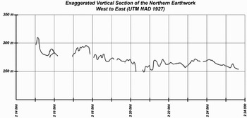
One of the attributes of the earthwork previously used to dismiss a hydraulic function is its propensity to snake up and down hills even over very short distances (Figure 5) (Puleston and Callender Reference Puleston and Callender1967:42; Webster et al. Reference Webster, Silverstein, Murtha, Martinez and Straight2004). Certainly this assessment is true if the earthwork were to be considered as a canal meant to move water over long lateral distances. In the model proposed here, the earthwork consisted of a series of modules, each catchment basin functioning independently of the others with no implication of a system of linear flow except from uplands to low zones within a particular catchment. In this case, each trough in the elevation chart (Figure 5) represents a basin, and the highs and lows would be necessary elements to the hydraulic function. To catch water and direct it, the earthwork ditch was cut into the slope of the hills with a downward gradient until it arrived at a bajo. Water following the subsurface hydraulic gradient would seep out of the upslope sides of the ditch where it could accumulate and flow downslope.
Profile graph of the North Earthwork illustrating the changes in elevation along the easting UTM (Webster et al. Reference Webster, Silverstein, Murtha, Martinez and Straight2004:Figure 17).

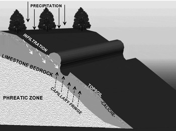
In addition to the water infiltrating through the vadose (nonsaturated) zone, the depth of the ditch could have tapped into or arrived near the phreatic zone (Figure 6). Because of the capillary fringe effect in porous stone, water would be pulled up from the underlying water table even if the 1.5–4.0-m deep ditch did not actually penetrate the phreatic zone. If the feature functioned as proposed here, there would have been a constant seepage of water into the ditch during the wet season, including the period of the canicula, because the water table would normally have risen in the initial weeks of the wet season. In this model, the porosity of the bedrock, which had also previously been used as an argument to rule out a hydraulic use for the earthwork (Puleston and Callender Reference Puleston and Callender1967:42), would in fact be an essential aspect of the hydraulic function.
A model of the relationship between the earthwork and hydrologic processes.

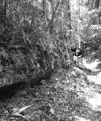
Evidence of the filtration process may be visible in portions of ditch wall that have been exposed since its original construction. Sections of the capstone crust have frequently been undermined and have collapsed in large pieces into the ditch. Such collapse happened when the top strata of hard caliche stone was undermined by erosion of the underlying sascab. The erosion of the soft cal substratum may have been caused by water percolating through the walls of the ditch and by carbonate dissolution (see Figure 4: Operation 104; Figure 7) (White Reference White1988:119–131). Originally it was thought that this might have been caused by runoff flowing over the side and eroding the softer rock below, but there is little indication of substantial runoff (i.e., vertical troughs or striated stains) and the collapse occurs on both upslope (south) and downslope (north) sides of the ditch. Birds and bees do nest and excavate in the soft cal, and tree roots tend to reach down the ditch wall, under the caliche, into the softer sascab so the collapse is probably attributable to a combination of bioturbations and hydrologic factors.
Photograph showing a section of wall collapse.

Several morphological aspects of the trench seem contrary to any sort of “barrier to human movement” defensive purpose and, in at least one case (see Figure 4: Operation 201), the shape of the ditch seems best suited to the movement of water. In seven ditch cross sections (see Figure 4: Operations 102, 6.2, 5.1, 7.4, 12.1, 105, and 201), a stoop or shelf of bedrock that was part of the original construction was found, or in some cases, the ditch walls were sloped rather than vertical (contrary to the presumed “standard” section dug by Puleston and Callender). Obviously if the ditch were meant to discourage human transit, vertical walls would be preferable. These shelves and inclinations would facilitate climbing out of the ditch and are more suited for maintenance than protection. In one section of the earthwork, on the east side of a 12.6-m wide bridge that is formed by a mass of the natural bedrock left in place, a small channel, 42 cm wide and 50 cm deep, is cut down the middle of the ditch (Figure 4: Operation 201). A section of the southeast earthwork also appears to have a channel in the center (Figure 4: Operation 105). It is difficult to attribute any function other than hydraulic to these channels.
Catchment Basins
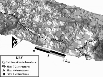
Perhaps the most convincing aspect of the northern earthwork is its relationship to catchment basins (Figure 8). If other possible functions of the earthwork are considered, such as a road, or a boundary with some defensive or barrier use, then why would anyone have constructed a feature that runs up and down slopes if more efficient and effective alternate routes that avoided bajos existed? The path of the earthwork purposefully and regularly slips down slopes into catchments where it usually disappears, only to be found again up on the opposite slope of the catchment. There were alternative routes if defense, ease of walking, or visibility were foremost in the calculations of the Maya engineers.
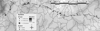
A model generated from a digital elevation map illustrating the relationship between catchments, settlements, the earthwork, and the topography. Note that settlements tend to be situated up slope and the earthwork appears to purposefully follow slopes toward the low ground.

As previously discussed, physiographic and hydrographic variations within individual watershed catchments in the Tikal hinterland presented an opportunity for local communities to vary subsistence activities. Cowgill (Reference Cowgill1961) recorded three maize crop strategies exercised by Peten milperos in the first half of the twentieth century: regular crops (planted April to May), San Jose crops (planted in early March), and Yaxkin (planted in early November). The latter two crops are planted to supplement otherwise weak yields of the regular crop. Milperos decide where to farm based on the nature of existing vegetation, soil consistency, their experience with particular plots, avoidance of highlands that are exposed to too much wind and sun, and avoidance of saturated lowlands that would retard maize growth. The dry season San Jose crop was planted in bajos that offered sufficient moisture, whereas the Yaxkin crop was planted on higher steeper land that would not be saturated at the end of the wet season (Cowgill Reference Cowgill1961:13–15). Access to the range of soils within a catchment basin would have offered farmers the means of diversifying planting strategies to mitigate risk or, if needed, as a response to other demands for increased productivity.
One possible consequence of diversified exploitation of watershed catchments is that the catchment itself could serve as a unit of socioeconomic organization. If this were the case, the expectation is that the settlement pattern would reflect this organizational parameter. Larger administrative centers might favor ridgetops that intersected multiple basins, and their spacing would show some correlation with the size of basins. Additionally, the catchment area as discussed in Flannery (Reference Flannery and Flannery1976:91–130) as “the zone of resources, both wild and domestic, that occur within reasonable walking distance of a given village” would be covered within one basin or a group of adjacent watershed catchments (Flannery Reference Flannery and Flannery1976:91). Certainly numerous factors weighed into Maya settlement choices. Our data from the northern earthwork carry significant bias because most were collected based on proximity to the linear feature. The apparent consistency of the distribution of plaza groups with the catchment basins, however, appears to correlate with the hydraulic model of the earthwork (Figure 9).
GIS map of the relationships among the elevation-derived catchment basins, the earthwork, and the settlement pattern along the earthwork.

Using ArcMap's (ESRI, Redlands, California) hydraulic analysis tools, the catchment basins that articulate with the northern earthwork were extrapolated from digital elevation map data (digital elevation data provided by the National Aeronautics and Space Administration/National Science Foundation AIRSAR [Airborne Synthetic Aperture Radar] project). The basins have an average area of 14.5 ha receiving approximately 195,000–290,000 m3 of annual precipitation. Of the 32 catchment basins that intersect the north earthwork, the average distance from the centroid of one basin to the next closest basin is approximately 430 m. Among the 39 groups recorded, the average distance to a nearest neighbor is approximately 200 m, and among groups with four or more structures it is 389 m. The spacing of groups is consistent with what might be expected if the catchment basins had some explanatory relationship with how the Maya settled the landscape. Future analysis will focus on modeling catchment production vis-à-vis settlement and population. For example, rough estimates made by Webster suggest that the catchments along the north earthwork might accommodate a population of 700–1,500 people, a rather small amount in proportion to the investment of construction effort.
Hydraulic Articulations
The biggest gap in our data is at the bajos where, according to the hydraulic hypothesis, the collected water would be put to use. Unfortunately, we have minimal excavation data from catchment bottoms. We did not focus our research efforts in the bajos primarily because this hydraulic model grew as data were accumulated and analyzed and it matured only after completion of the fieldwork. The dry season Vertisols are also extremely difficult to work and excavating in the bajos would have yielded only limited information for the amount of project resources invested. Operation 4, however, did reopen the trench where Puleston and Callender (Reference Puleston and Callender1967) claimed to have seen evidence of the ditch continuing through the bajo, leading to the conclusion that the earthwork was a continuous linear feature in spite of the lack of visible surface evidence. Here Silverstein found evidence of Maya excavations, but his interpretation varies from that of Puleston and Callender (Reference Puleston and Callender1967). The profile of the south wall of the Operation 4.3, based on the projected prolongation of the earthwork, should show a level or slightly graded floor in an east-west direction. Instead it shows what appears to be an ancient excavation, but one that scoops downward (Figure 10). The curved cut in the Vertisol appears more consistent with a shallow aguada or possibly a lateral trench. At this point, there are simply too few data to confidently interpret this feature. The profile, while supporting the idea that bajo constructions did articulate with the earthwork, casts doubt on the assumption that the ditch continued as a single linear feature across the bajos. Considering the sticky clay consistency of the Vertisols during the wet season, it is difficult to imagine how any construction other than broad shallow aguadas could have been reasonably maintained.
South wall profile of Operation 4.3. The floor of the paleo-excavation suggests something other than a continuation of the earthwork in the bajo.

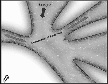
Two other features of the earthwork strongly suggest a hydraulic function: one is the 300-m bifurcation that leads directly to the aguada El Duende, and the second is a five-way junction that appears to link four branches of constructed earthwork with a wide shallow arroyo (Figure 11; see Figure 9 for location of junction). The bifurcation, which leads out of the large western bajo where Puleston had originally thought the west side of the northern earthwork terminated, is, with little doubt, designed to carry water to the aguada. Although this section of earthwork was initially viewed as an anomaly, and possibly a late addition and adaptation, it may be that this segment and aguada are actually an example of the best-preserved section illustrating the primary function of the earthwork. A hydraulic function for the other junction is less clear, but it is difficult to interpret the five-way intersection otherwise.
A sketch map of the five-way junction on the eastern half of the north earthwork.

The Lineation Problem
If the earthwork was conceived of as a series of hydraulic projects, each focused on a particular catchment, why does it form a more or less contiguous line in the north (and not just in the north, but elsewhere as well)? This aspect of the earthwork is perhaps the most perplexing and least coherent with the hydraulic hypothesis. Several alternate functional hypotheses are consistent with the linear form, including a territorial boundary and a communications route. The original embankment would have consisted of bright white berms of soft limestone that conceivably functioned as a sacbe (literally “white way”) linking the sites along the northern hinterland. This is sheer speculation, however, and the embankment still seems to be best interpreted as a linear pile of spoil. In addition to any other function, the embankment may have also operated to preserve the ditch (Vern Scarborough, personal communication 2006). It is almost always on the upslope (usually south) edge. Surface erosion is not a major problem; but if the uphill edge of the ditch were not reinforced, the adjacent soil could become soft during heavy rains and infill the ditch. The embankment would halt or reduce this process.
The Chronology Problem
One of our main objectives was to obtain ceramics and carbon that would allow us to date what was thought to be a defensive wall and align it with the political history of Tikal. In spite of our efforts, we were unable to definitively solve the chronology issue (Webster, Silverstein, Murtha, Martinez, and Straight Reference Webster, Silverstein, Murtha, Martinez, Straight and Cobean2007:55–56). Variations in the ditch morphology, the apparent addition of branches, and an interpretation of two phases of construction at Puleston's bridge excavation (Puleston and Callender Reference Puleston and Callender1967:45) as well as Silverstein's interpretation of two phases of construction in the adjacent embankment (Webster et al. Reference Webster, Murtha, Straight, Silverstein, Martinez, Terry and Burnett2005) (Figure 10) might indicate that the earthwork grew in phases over an extended period of time. As it stands, there are simply too few data to do more than state that the earthworks were probably constructed some time during the Early through Late Classic periods. In view of the recent advances in Classic period Maya environmental reconstruction (e.g., Gill Reference Gill2000; Webster, Brook, Railsback, Cheng, Edwards, Alexander, and Reeder Reference Webster, Brook, Railsback, Cheng, Edwards, Alexander and Reeder2007), dates for the earthwork might link with the growing body of data on drought stress. At this point, though, such speculations outpace our understanding of the earthworks and are best reserved for the next phase of investigation.
An Analogy: Galerías Filtrantes
Silverstein's original concept of the earthwork as a water collection feature was inspired by his experience with galerías filtrantes in semi-arid Puebla, Mexico (Beekman et al. Reference Beekman, Weigand and Print1999; Palerm and Sanchez Reference Palerm Viqueira, Equihua and Rodriguez2002). Galerías filtrantes in Mexico are generally attributed to the Colonial period and thought to be an import from Iberia/Canary Islands. They consist of subterranean channels cut through hillsides. They are designed to capture subsurface water filtering downslope and then direct the water via the underground aqueduct to a reservoir or populated area. Galerías filtrantes are generally cut perpendicular to the grade of a hillslope, with floors that run downslope askew of the contours to the target location. An example explored by Silverstein in 1994 consisted of an 8-m access well leading from the surface down to a 20 m deep–by–1 m wide trench that extended for an unknown distance across the hillslope. Light was visible from other access wells spaced approximately 50–100 m apart along the length of the trench. Water seepage occurred at the bottom even during the height of the dry season and where the floor of the trench was well above the water table. This cultural adaptation was meant to take advantage of seasonal precipitation in an environment where water was a limited commodity and where well construction was difficult because of the hydrogeology. Other examples of systems that functioned in one aspect or another similar to the limestone filtration trench proposed here include Peruvian filtration puquios (Schreiber and Lanche Rojas Reference Schreiber and Rojas1995, Reference Schreiber and Rojas2003) and South Asian sailaba, which are used to collect rain runoff to fill shallow reservoirs that are then used to maintain soil moisture for farming in arid lands (growing season rainfall at 350–450 mm) (Hanan Reference Hanan2006; Kahlown and Hamilton Reference Kahlown and Hamilton1996).
DISCUSSION
This paper has focused on the northern earthwork because it consists of the most complete sections with the most available data. The model is generally consistent (and in some cases more consistent because there is no lineation problem) with other sections of the earthworks west and southeast of the Tikal acropolis. The hydraulic hypothesis carries with it several layers of significance pertinent to reconstructions of Classic period Tikal, to our understanding of adaptive strategies of the Lowland Maya, and to archaeology in general. Perhaps the most important lesson learned is that hypotheses remain hypotheses until a preponderance of evidence can be brought to bear that either proves, disproves, or modifies the original proposition. Puleston and Callender's (Reference Puleston and Callender1967) interpretation of the earthworks as a defensive perimeter and the associated territorial implications were readily incorporated into the body of Maya literature without the benefit of a more complete investigation. Our earthwork project initially accepted their interpretation and the resultant body of data that argues against the defensive model was unexpected. The project was conceived of only because Webster, whose career in the study of Maya warfare and whose excavations at Becan (Webster Reference Webster1972, Reference Webster1973) was in many ways inspired by the discovery of the earthworks, was apprehensive about the paucity of supporting data. After three seasons of work on the earthworks, the archaeologists who participated in our project are still struggling with how to interpret the new data concerning this enigmatic feature.
The hydraulic function first became plausible with the discovery that the bifurcation in the northwest corner of the earthwork terminated in an aguada. It is difficult to explain this segment of the feature as other than a hydraulic construction, although it could not be ruled out as a later addition built after defensive or boundary functions of the earthwork had become obsolete. The members of the team later found the dry season shortage of water at Zocotzal suggestive. Placing the earthwork within the context of the limestone hydrology, microenvironmental variance, and seasonal water stress, we conceived a hypothetical model of how the Maya could have used the earthwork to capture precipitation and thereby mitigate the risk of crop loss, particularly during the canicula.
This hydraulic model is untested and the nuances in the relationship between hydrology and the form of the earthwork, between Maya agricultural practices and settlement organization, and between the paleo-environment and the modern environment could undermine it. Filtering water might travel downward through the limestone faster than anticipated, effectively bypassing the ditch, and the phreatic zone might never rise to a sufficient level to accumulate water in the ditch. The agricultural purpose and seasonal temporality of the earthwork proposed here are circumstantial and not currently supported by direct evidence. We also do not know the extent to which the canicula in the Tikal region is a threat to crops, given the capacity of soils to store moisture, or that the primary purpose of the earthwork was the capture of potable rather than agricultural water, as proposed for the lagoons of Copan (Davis-Salazar Reference Davis-Salazar2003). Other possible hydraulic functions should not be ruled out a priori. For instance, at the bifurcation in the northwest, the trench might have drained water from a bajo to the aguada El Duende, although the slope of the ditch is incorrect. Also, even though the canicula seems to present a considerable hazard to the maize-growing period, it is certainly possible that the earthworks served to support limited or emergency farming such as the San Jose crops conducted during the dry season by using shallow canals to irrigate milpas located on the peripheries of the bajos. This said, our working hypothesis is that a major function of the earthworks was hydraulic and that use as a limestone filtration trench is the most parsimonious explanation for many of the characteristics of the earthwork system. The other main alternative, to which Webster is still inclined, is that the earthworks served primarily as some kind of boundary.
The most troubling piece of the hydraulic model remains the east-west linear arrangement of the north segments. It is logical to surmise that the continuous line of the earthwork was conceived by a centralized authority. Even though the northern earthwork fails to meet expectations of a city wall, it would have presented a substantial barrier in many places and it could have served as some sort of territorial demarcation in the north and west. It appears as though the engineers of the earthwork conceived of it as a multifaceted construction that addressed issues beyond hydrology, possibly including communications, territorial demarcation, quarrying, and defense. Quarrying might have been of more importance than originally thought. Recent research has shown that the hard cap of caliche limestone was the most desirable stone for the production of quicklime (Schreiner Reference Schreiner2002). Profiles of the embankment suggest that the hard caliche stone is underrepresented in the mix, perhaps indicating that it was removed for quicklime production or as building stone.
Testing the hydraulic hypothesis will require further surveys, excavations in bajos, analysis of land use, geohydrologic studies of fluctuations in the water table, and directed excavations on the earthworks with open sections observed during the rainy season. Localized measurements of seasonal fluctuations in the phreatic zone, the strength of the capillary effect, and seasonal variations in the bajos would go a long way in proving or disproving what we have presented here.
The view of the catchment area as a natural organizational parameter in the Tikal hinterland has powerful implications not only for the role of the earthwork in Maya agriculture at Tikal, but also for Maya settlement organization in general (de Montmollin Reference de Montmollin1989:197–205; Flannery Reference Flannery and Flannery1976). If this is the case, the construction, function, and maintenance of the earthwork could be tied to the local elite groups, while the linear arrangement of the groups still suggests an expression of centralized authority from the acropolis.
RESUMEN
Desde 1966 el terraplén de Tikal ha sido considerado como el más grande y mejor ejemplo de la arquitectura defensiva de las Tierras Bajas de los Mayas. A partir de los más de 10 kilómetros de mapeados por el Proyecto Área Sustentable de Tikal (Tikal Sustaining Area Project) se tenía la idea de que las fosas y los parapetos que conforman dicho terraplén formaban parte de este sistema defensivo, cuyos límites, al norte y sur marcaban la extensión total del sitio de Tikal, dejando los extremos este y oeste protegidos por la zona de los bajos. Sin embargo, durante las más recientes investigaciones del Proyecto Estudio de las Fortificaciones de Tikal (EFAT), se han mapeado otros 14 km de este terraplén. Las nuevas áreas mapeadas, así como la evidencia recolectada en las excavaciones de la construcción, nos ofrecen información substancialmente distinta a la idea de que este terraplén tenía una función defensiva. Así, se ha podido observar que la orientación y extensión de este terraplén no marcan realmente las fronteras del sitio de Tikal, tal como se había pensando anteriormente; ni que tampoco esta construcción tenía un fin defensivo. Con base en esta información aquí se propone que el terraplén pudo haber funcionado como una fosa de captación caliza de agua subterránea para mitigar los efectos de la canícula en la época de siembra o para sustentar cultivos fuera de la temporada de lluvias.
ACKNOWLEDGMENTS
Our fieldwork was made possible by the generous support of the National Science Foundation (Grant No. BCS-0443280) and institutional support from Pennsylvania State University, the University of San Carlos, Guatemala, the Parque Nacional de Tikal, the Instituto Nacional de Antropología e Historia (IDAEH), the Central Identification Lab of the Joint POW/MIA Accounting Command, and Brigham Young University. The genesis of the ideas presented here would not have been possible without the input and/or labor of Timothy Murtha, Kirk Straight, Hector Escobedo, Irinna Montepeque, Richard Terry, Rich Burnett, Vern Scarborough, Stephen Houston, the workers from Dolores, Claudia Wolley, Nicholas Dunning, Keith Prufer, Timothy Beach, August Goodman, and Jim Pokines.