Introduction
“Monolith” in this article is used to represent porous materials that have a three-dimensional continuous interconnected porous structure. Polymer-based monoliths possess some excellent properties, such as predominant pH stability, nonspecific interaction, specific pore properties, and easy functionalization in contrast to silica-based monoliths [Reference Sun, Fujimoto and Uyama1]. Furthermore, polymer-based monoliths with porous structure are of great interest in various fields due to their superior performance such as high porosity, large specific surface area, and fast mass transfer performance. In the past 30 years, polymer-based monoliths have been widely used for chromatography [Reference Lv, Lin and Svec2], enzyme immobilization [Reference Bolton, Canty, Deverell, Guijt, Hilder, Rodemann and Smith3, Reference Sun, Xin, Wang and Uyama4], oil sorbent [Reference Liu, Huang, Gao, Zhang, Chen, Xu, Gao, Pan, Yang and Liu5, Reference Wang, Chen, Zhang, Li, Liu, Chen and Shen6], tissue engineering [Reference Patrício, Domingos, Gloria, D’Amora, Coelho and Bártolo7, Reference Rezabeigi, Wood-Adams and Drew8], and so on.
As a new kind of porous materials, polymer monoliths are not only characterized by the porosity to evaluate their porous structure in recent years. The aperture size and distribution have also come into researcher’s view. According to the pore size, the pores are divided into micropore (<2 nm), mesopore (2–50 nm), and macropore (>50 nm). Materials simultaneously containing more than two kinds of pores are called hierarchical porous materials. Nowadays, hierarchical porous materials have attracted more and more attention due to their excellent properties induced by the complex porous structure.
Typically, hierarchical porous monoliths are fabricated by combining electrospinning with 3D printing technology [Reference Kang, Wang, Qiao, Gu, Zhang, Peijs, Kong, Zhang and Shi9], multiple-template method [Reference Dhainaut, Dacquin, Lee and Wilson10, Reference Hiroaki Sai, Hur, Asenath-Smith, Hovden, Jiang, Riccio, Muller, Elser, Estroff, Gruner and Wiesner11], lithography [Reference Morariu, Voicu, Schaffer, Lin, Russell and Steiner12], phase separation [Reference Sun, Fujimoto and Uyama1, Reference Okada, Nandi, Maruyama, Oka, Tsujimoto, Kondoh and Uyama13, Reference Önder, Yilgör and Yilgör14, Reference Wang, Xin and Uyama15, Reference Xin, Fujimoto and Uyama16, Reference Xin and Uyama17, Reference Yoneda, Han, Hasegawa and Uyama18], and so on. The organic template used for the multiple-template method is usually expensive, whereas the lithography usually possesses a complex process. In contrast, the phase separation method is facile, and the morphology of the porous structure can be easily controlled by changing the process parameters [Reference Sun, Sun and Wang19], such as the type of nonsolvent and replacement solution, standing temperature, and polymer concentration. Freeze-drying method is also a traditional way to fabricate porous materials. However, according to this method, hierarchically porous structures are hard to be obtained because of the different pore-forming mechanism [Reference Huangfu, Liang, Han, Qiu, Song, Wang, Kong and Gu20, Reference Huangfu, Ruan, Qiu, Lu, Liang, Kong and Gu21].
Phase separation mainly includes nonsolvent-induced phase separation (NIPS) [Reference Xin and Uyama17], thermal-induced phase separation (TIPS) [Reference Okada, Nandi, Maruyama, Oka, Tsujimoto, Kondoh and Uyama13], and thermally impacted nonsolvent-induced phase separation (TINIPS) [Reference Sun and Uyama22]. Phase separation method is traditionally used to prepare porous membrane materials, and the pore size obtained is usually larger than 50 nm, that is to say, all the pores obtained by traditional phase separation method are macropores. However, Uyama’s team [Reference Okada, Nandi, Maruyama, Oka, Tsujimoto, Kondoh and Uyama13, Reference Wang, Xin and Uyama15, Reference Xin and Uyama17, Reference Sun and Uyama22, Reference Han, Yamauchi, Hasegawa, Noda, Fukui, van der Vlies, Uchiyama and Uyama23, Reference Park, Sakamoto, Sung and Uyama24, Reference Sun and Uyama25, Reference Wang and Uyama26, Reference Wang and Uyama27] proposed that phase separation method could be applied to prepare the porous monoliths containing both macropores and mesopores. So far, various polymer monoliths have been prepared successfully by phase separation method, such as polycarbonate monolith [Reference Xin, Fujimoto and Uyama16], poly(vinyl alcohol) monolith [Reference Sun, Fujimoto and Uyama1, Reference Sun, Xin, Wang and Uyama4], poly(methyl methacrylate) monolith [Reference Yoneda, Han, Hasegawa and Uyama18], and so on.
Poly(L-lactic acid) (PLLA) is a kind of aliphatic thermoplastic polyester with biocompatibility, biodegradability, and good mechanical strength. However, it also has some weaknesses such as thermal instability and low flexibility, which restrict its applications. Poly(ε-caprolactone) (PCL) is a kind of semicrystalline polymer with biocompatibility, biodegradability, high flexibility, and nontoxicity. Nevertheless, the poor mechanical strength of PCL and the low flexibility of PLLA restrict their applications in biomedical field [Reference Sabir, Xu and Li28]. To obtain better mechanical performance, the PLLA/PCL composites are preferred. To date, the fabrication of PLLA/PCL composites has been conducted by melt blending [Reference Patrício, Domingos, Gloria, D’Amora, Coelho and Bártolo7], solvent casting methods [Reference Patrício, Domingos, Gloria, D’Amora, Coelho and Bártolo7], and electrospinning method [Reference Dong, Zhang, Pang, Chen, Qi, You and Ren29]. However, there are few reported lectures focusing on the PLLA/PCL composites prepared by phase separation method.
Tissue engineering scaffolds require biocompatibility, biodegradability, a good interconnection of pores, ideal mechanical properties, and high porosity. Such requirements are not only for pure materials, but also for the composites. For an ideal scaffold for tissue engineering, a multiscale porous structure is crucial as well [Reference Shadjou and Hasanzadeh30]. Both micropores and mesopores would not only provide the materials with larger specific surface area, but also facilitate the nutrient and waste exchange; macropores would endow the porous materials with more available space, which was beneficial for the adhesion and growth of the cell for tissue engineering.
The polymer monoliths with both mesopores and macropores have great potential for the field of tissue engineering. As reported, the morphology of the polymer monolith obtained by phase separation method was easily tuned [Reference Xin and Uyama17]. To control the porous structure more accurately, it is necessary to understand the forming mechanism of pores in the forming process of monolithic materials by phase separation method. However, most of the literature only explained the formation mechanism of macropores during phase separation, whereas few studies have been conducted on the formation mechanism of mesopores and micropores. Sun and her coworkers [Reference Sun, Cao, Bao, Liu, Xie, Yang and Yang31] proposed in their research that the microphase separation of poly(lactic acid) monolithic materials in melt phase separation resulted in the existence of mesopores and micropores. And the microphase separation was due to the stereocomplex crystalline formation of PLLA/PDLA. However, for the system of NIPS, there has been still no reliable theory supported by other researchers.
In this study, PLLA/PCL monolithic composites with both macroporous and mesoporous structures were fabricated by NIPS without any template for the first time. The method in this article is facile, green, and low cost as long as the types and weight ratio of solvent and nonsolvent are confirmed. The morphology and thermal performance of resultant monoliths were investigated in detail. The forming mechanism of hierarchical porous structure fabricated by NIPS was also discussed for the precise control of the hierarchical porous structure. Considering the properties of the composites, we believe that the obtained monoliths have great potential applications in the field of tissue engineering.
Results and discussion
Morphologies of monolithic composites
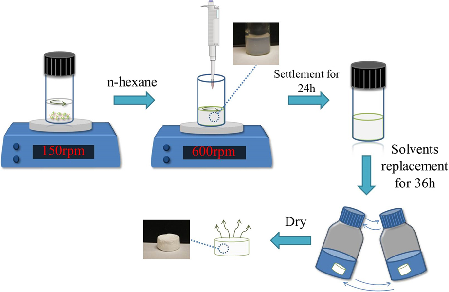
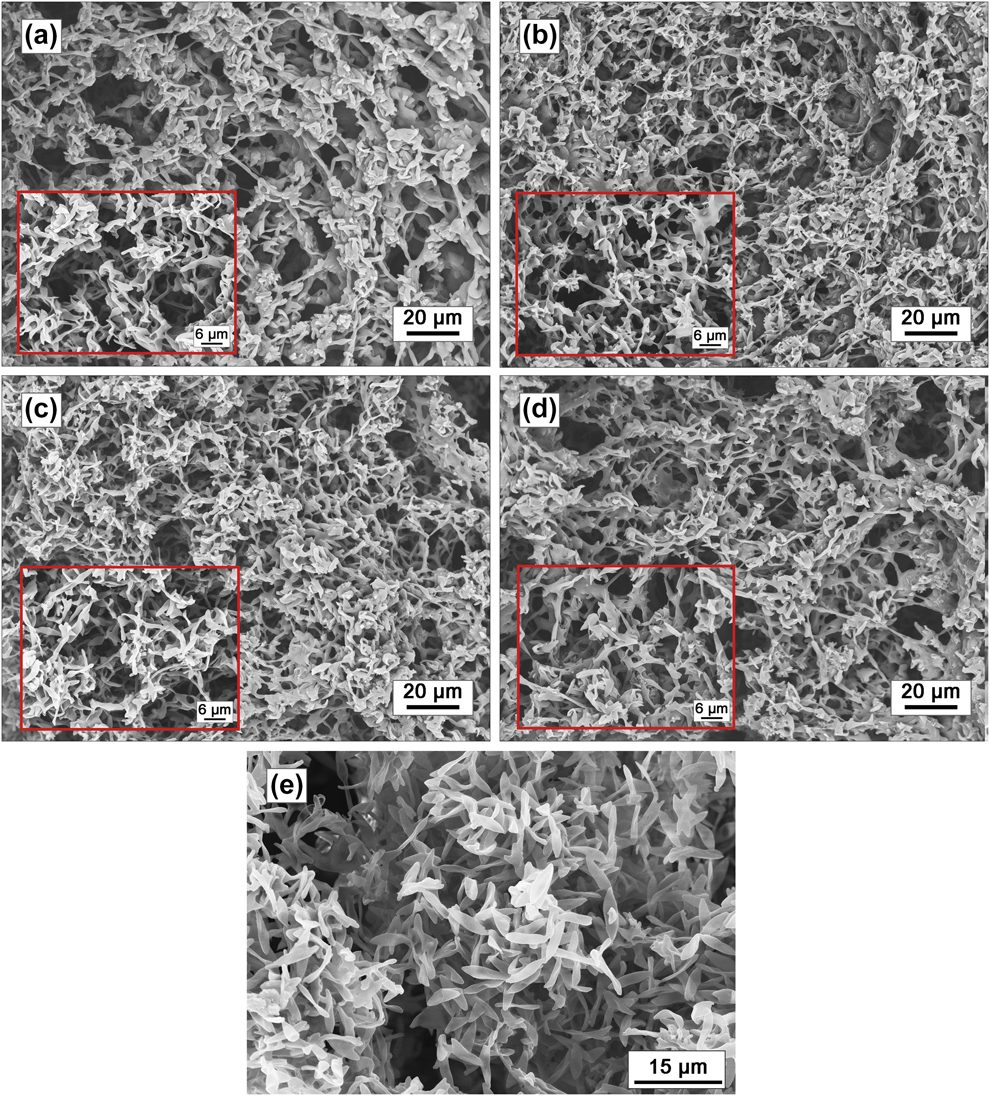
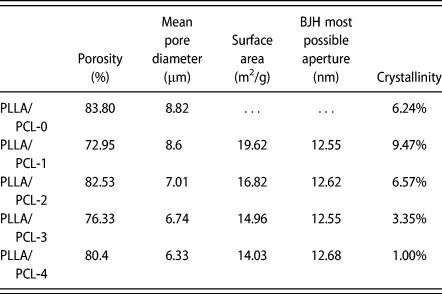
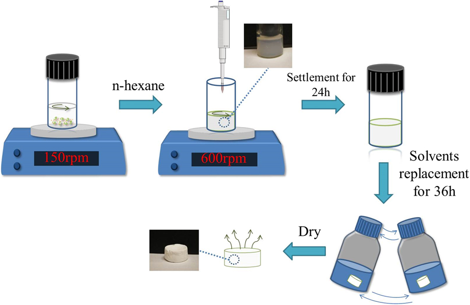
The monolithic composites with a polymer concentration of 13 wt% in DCM for different PLLA/PCL weight ratios were prepared by NIPS. Scheme 1 illustrates the preparation process of the monolithic composites. The morphology of these monolithic composites and PLLA monolith is shown as Fig. 1, from which a relatively homogeneous hierarchical porous structure could be observed. The porosity of as-prepared composites calculated by volume ratio method is shown in Table I. Obviously, the porosity of all the samples was above 72%, and the PLLA/PCL-0 had the highest porosity of 83.8%. Such polymer skeletons were formed by the aggregation of PLLA and PCL particles during phase separation, forming the irregular and interconnected pores. The skeleton structure of the composites was different from that of the pure PLLA monolith [Fig. 1(e)]. During the crystallization process of PLLA in composites, growing spherulites on phase boundary of PLLA and PCL lead to the termination of crystallization, which affects the macroscopic morphology and gives rise to the different morphology between the composites and pure PLLA monolith.
Fabrication process of PLLA/PCL monolithic composites.
SEM images of (a) PLLA/PCL-1, (b) PLLA/PCL-2, (c) PLLA/PCL-3, (d) PLLA/PCL-4, and (e) PLLA/PCL-0.

Basic parameters of monolithic composites.

Hierarchical porous structure of monolithic composites
As for the hierarchical porous structures, mean macropore diameters were calculated from Fig. 1 using Nano Measurer 1.2 software, which are shown in Table I. With the increase content of PCL, the pore size decreased gradually from 8.82 to 6.33 μm. As the nonsolvent is added into the polymer solution, the system becomes unstable and turns into polymer-rich phase and polymer-lean phase. When the system is in metastable state, the phase separation mechanism is nucleation and growth. On one hand, with the increase of PCL, the viscosity of the system increases and the gel time is shortened, thereby inhibiting the phase separation and resulting in smaller pore sizes; on the other hand, with the increase of PCL, the proportion of nonsolvent becomes less, leading to smaller driving force for phase separation so that the pore sizes become smaller.
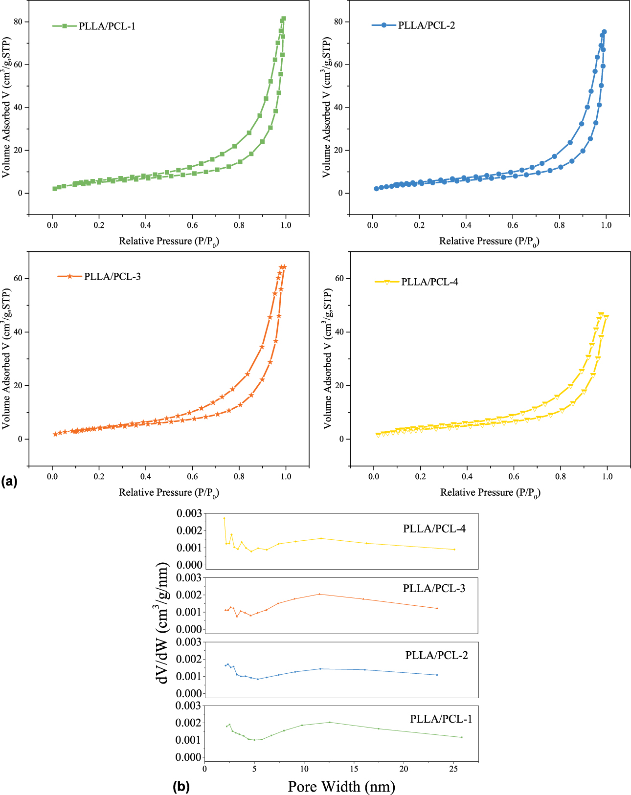
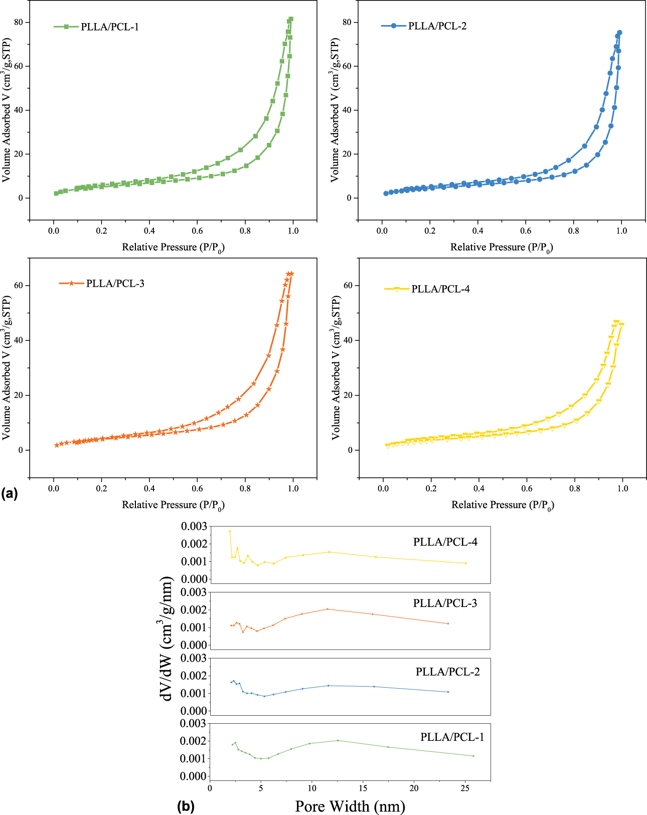
Mesoporous structures were characterized by nitrogen adsorption–desorption tests. The specific surface areas of the monolithic composites measured by BET method are shown in Table I as well. As shown in Fig. 2(a), the nitrogen adsorption–desorption isotherms for all the PLLA/PCL monolithic composites belonged to type IV, and the hysteresis loops in the relative pressure range from 0.5 to 1.0 were all attributed to type H3, which represented the existing of mesoporous structure. Pores of type H3 are often considered as slits formed by the accumulation of plate-like particles, which was consistent with that of the scanning electron microscopy (SEM) images. The pore size distributions of all the composites obtained by BJH method are shown as Fig. 2(b) and the most possible apertures are listed in Table I. The most possible apertures of all the monolithic composites were centered on around 12 nm. The data obtained from the pore size distributions further clarified the existence of the mesopores. The results of SEM and BET show that PLLA/PCL monolithic composites fabricated in this study were hierarchical porous materials with both nanoscale pores and large pores.
(a) Nitrogen adsorption–desorption isotherms and (b) pore width distribution for all the PLLA/PCL monolithic composites.
Characterization of monolithic composites
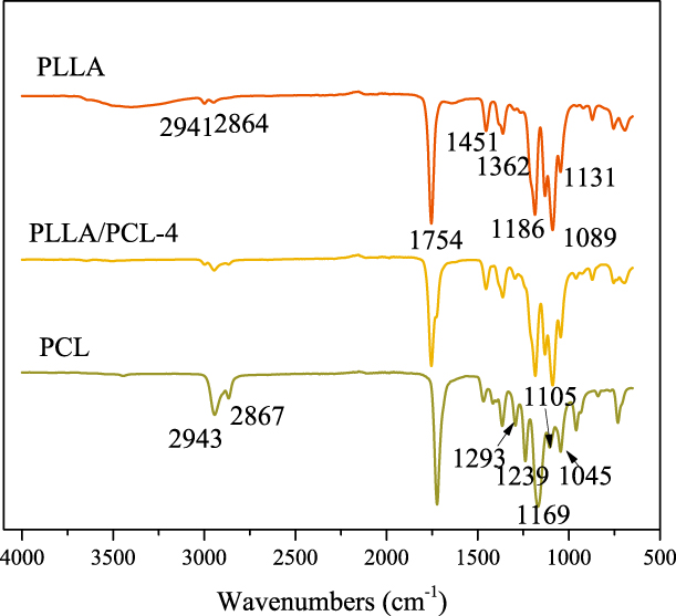
Fourier transform infrared (FTIR) measurement was performed to investigate the interaction of monolithic composites. PLLA/PLC-4 was chosen as the sample, and the results are shown as Fig. 3. In the spectrum of PLLA, a strong peak at 1754 cm−1 was ascribed to the stretching absorption of the C=O. The peaks at around 2941 and 2864 cm−1 were assigned to the –CH stretching. The peaks at 1451 and 1362 cm−1 were attributed to –CH3 and –CH bending, respectively. The peaks at 1186, 1131, and 1089 cm−1 were assigned to the C–O stretching. The spectrum of PCL showed a strong peak at 1723 cm−1 attributing to the C=O stretching. Peaks at 2943 and 2867 cm−1 were assigned to the –CH2– stretching vibration. Peaks at 1293 cm−1 and 1169 cm−1 were ascribed to the C–O group and C–C group, respectively. The peaks at 1045, 1105, and 1239 cm−1 were mainly caused by the C–O–C stretching. PLLA/PCL-4 retained the characteristic peaks of PLLA and PCL. There were no new characteristic peaks generating, indicating that the two are physically blended.
FTIR spectroscopy of PLLA, PLLA/PCL-4, and PCL.
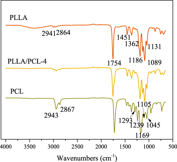
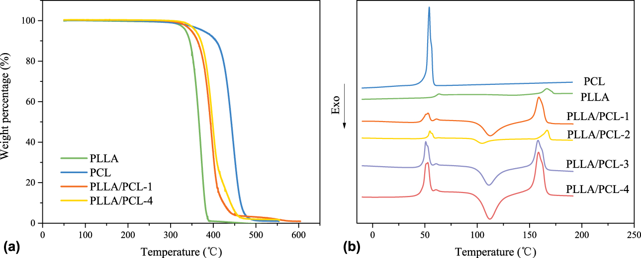
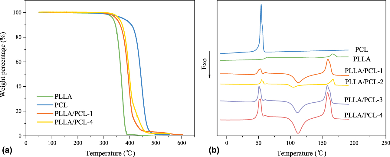
Figure 4(a) shows the thermal gravimetric analyses (TGA) curves of PLLA particles, PCL powder, and PLLA/PCL monolithic composites (PLLA/PCL-1 and PLLA/PCL-4), respectively. The temperature at 5% weight loss (T 5%) of PLLA and PCL was about 335 °C and 376 °C, respectively. And the T 5% of the composites was between those of PLLA and PCL. Hence, we think that all the samples had good thermal stability under 300 °C. The thermal compatibility of the monolithic composite is observed from the second heating curve of differential scanning calorimeter (DSC) in Fig. 4 that the melting temperatures of PLLA and PCL were about 160 °C and 51 °C, respectively. When blended, no new melting peaks appeared, indicating no chemical reaction between PLLA and PCL in the composites occurred. Additionally, the melting temperature of the blends was roughly the same as that of the pure PCL and PLLA but with a slight close approximation between the two melting peaks, showing that there was a slight compatibility between PLLA and PCL. Moreover, each polymer formed an independent crystallization region on the curves of all the composites, which was consistent with the results of FTIR analysis. Contrast to the DSC curve of the pure PLLA, the area of cold crystallization peaks became larger in those of the monolithic composites with the increase contents of PCL, which indicates the imperfect crystallization of PLLA caused by addition of PCL. Among the blends, the crystallinity of PLLA decreased with the addition of PCL. However, the crystallinity of PLLA/PCL-1 was higher than that of the pure PLLA (as shown in Table I). During the preparation process, PLLA and PCL small particles first precipitate from the solution with the slow dropwise adding of n-hexane, functioning as crystal nucleus. Small amount of PCL nucleus promotes the crystallization of PLLA; however, when the amount of PCL increases to certain value, PCL nucleus and PCL molecules impede the movement of PLLA molecular chains and eventually inhibit the crystallization of PLLA.
(a) TGA curves of PCL, PLLA, and monolithic composites. (b) Secondary heating curves of DSC.
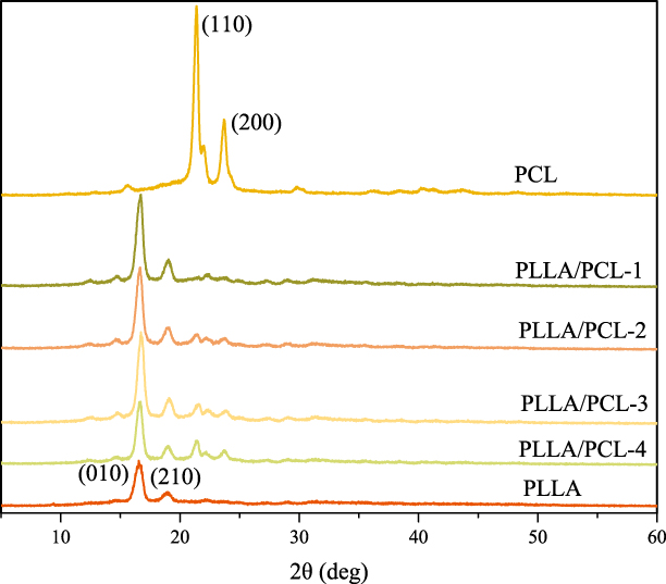
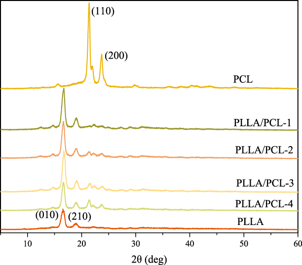
The results of X-ray diffraction (XRD) tests are shown in Fig. 5. It can be seen that the crystal forms of PLLA and PCL when blended were the same as those of the pure PLLA and pure PCL. The patterns of PCL displayed sharp and strong crystalline peaks at about 21.38° and 23.68°, which were ascribed to the (110) and (200) crystallographic planes, respectively. And the characteristic peaks of PLLA occurred at about 16.56° and 19.00° were in virtue of the (010) and (210) crystallographic planes, respectively. There was no new crystalline peak in XRD curves of the monolithic composites, further proving that the PLLA and PLC were physically blended and no new crystalline form was produced. However, with the increase content of PCL, the diffraction intensity caused by PLLA crystallization became smaller, indicating that PCL acts as a hindrance for the crystallization process of PLLA. And the detailed crystallinity of PLLA calculated from the second heating curves of DSC is listed in Table I. The results also show that the crystallinity of PLLA indeed decreased with the increase of PCL in monolithic composites, which was consistent with the results of XRD tests. Generally, the addition of PCL indeed affected the crystallization of PLLA, which supports the conclusion that the difference of the morphologies of the PLLA monolith and composites was due to termination of crystallization occurring on the phase boundary.
XRD curves of PCL, PLLA, and all monolithic composites.
Mechanism of hierarchical porous structure formation
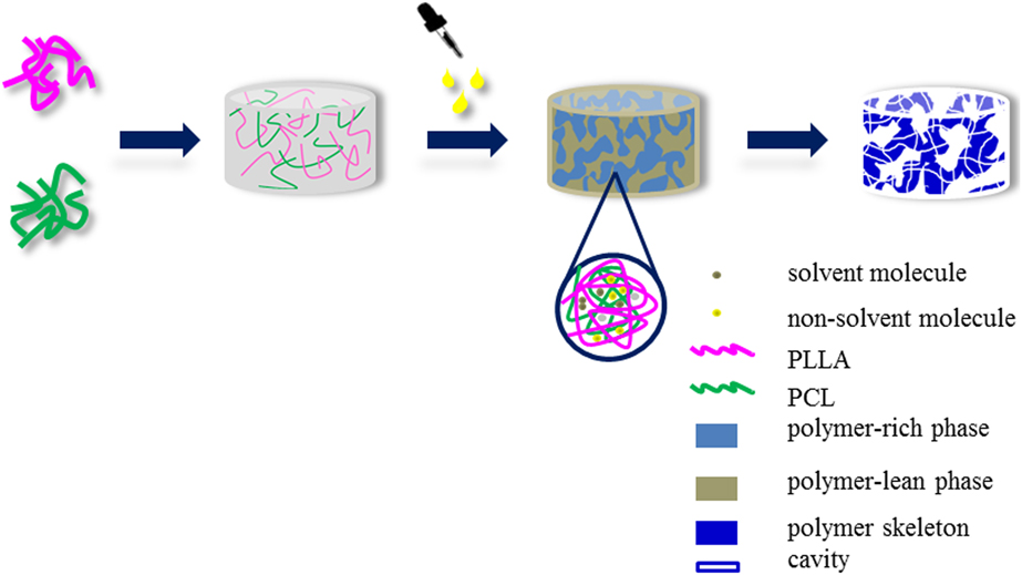
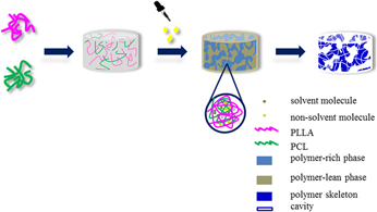
Based on all the above results, the formation of hierarchical porous structure is closely related to the crystallization process of the polymers. On one hand, as shown in Fig. 6, when the nonsolvent is added, the system becomes unstable, and the macropores are generated by the macrophase separation of polymer-rich phase and polymer-lean phase, which is induced by the driving force generated by the nonsolvent. The polymer-rich phase and polymer-lean phase are three-dimensional and continuous, respectively, leading to a three-dimensional continuous open macroporous structure as shown in SEM images. On the other hand, during the crystallization process, a portion of nonsolvent and solvent molecules are wrapped by polymer chains. There is no enough time for those nonsolvent and solvent molecules to aggregate with each other before the solidification of monolithic composites, which brings about the microphase separation. After the replacement and drying process, the nonsolvent and solvent molecules wrapped by polymer chains are also washed out, and then the mesoporous structure is formed (as shown in Fig. 6).
Forming mechanism of hierarchical porous structure.

In addition, the polymer particles are constantly coarsened during phase separation. When the coarse particles stacked with each other, the mesoscopic slit holes will be formed, which might give rise to type H3 hysteresis loops in nitrogen adsorption–desorption tests. In general, both macrophase and microphase separation occurring in the gel-forming process result in such hierarchical porous structure of monolithic materials.
Conclusion
In summary, we facilely fabricated the sustainable, degradable, and three-dimensional interconnected porous PLLA/PCL monolithic composites with both mesopores and macropores through NIPS method by choosing appropriate nonsolvent and determining the correct solvent/nonsolvent ratios. The preparation route is facile and green to realize. And the phase separation mechanism presented in this article explained the forming progress of mesopores by NIPS method, providing a basis for the precise control of the hierarchical porous structure. We believe that the macroporous structure was due to the macrophase separation induced by nonsolvent, whereas mesoporous structure was attributed to the microphase separation occurring during crystallization, and the microphase separation was due to that the solidification of polymers occurred before the solvent and nonsolvent molecules aggregate completely. The macrostructure afforded the monolithic composites with large specific surface area, which was beneficial for the adhesion and growth of the cell, and the mesoporous structure facilitated not only the increase of specific surface area but also the nutrient and waste exchange. Therefore, considering the nontoxicity and biodegradability of the raw materials and the hierarchical porous structure of the obtained monolithic composites, we believe that the PLLA/PCL monolithic composites presented in this study are of great potential in the tissue engineering field.
Experimental
Materials
PLLA pellets (M w = 1 × 10⁵ g/mol) and PCL powders (M w = 8 × 10⁴ g/mol) were purchased from Shenzhen Esun Industrial Co., Ltd., Shenzhen, China. Dichloromethane (DCM, AR, ρ = 1.32 g/cm3) and n-hexane were supplied by Sinopharm Chemical Reagent Co., Ltd., Shanghai, China. Methanol (AR) was obtained from Sinopharm Chemical Reagent Co., Ltd., Shanghai, China.
Fabrication of PLLA/PCL monolithic composites
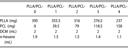
A general fabrication process is illustrated as Scheme 1. Typically, a series of mixing solutions with different weight ratios of PLLA and PCL (100:0, 90:10, 80:20, 70:30, and 60:40) was prepared by dissolving these polymers in DCM under strong magnetic stirring at room temperature for 1.5 h, and then a certain amount of n-hexane was added dropwise as nonsolvent while the solution stirring. The specific dosage of chemicals used in this article is listed in Table II. Note that fast dropping of nonsolvent might lead to local phase separations so that it should be avoided. The polymer concentration of the solution used in this article was 13 wt%. Afterward, the resultant solution was kept at room temperature for 24 h during which phase separation occurred to form a white wetting gel. The gel was then immersed in excess methanol and shaken in a shaker for 36 h to replace the residual solvent, and methanol was changed every 12 h. Finally, the obtained monoliths were dried under vacuum for 3 h. PLLA/PCL-0, PLLA/PCL-1, PLLA/PCL-2, PLLA/PCL-3, and PLLA/PCL-4 were used to represent the samples containing 0 wt%, 10 wt%, 20 wt%, 30 wt%, and 40 wt% PCL, respectively.
The formulas of PLLA/PCL monolithic composites.

Characterization
The morphology of the monolithic composites was observed by scanning electron microscopy (SEM; Hitachi TM3000, Hitachi Ltd., Tokyo, Japan) using secondary electron mode under high vacuum. The composites were coated with Au using an ion sputtering equipment (SBC-12, KYKY Technology Co., Ltd., Beijing, China) for 1 min before taking SEM images. And the best morphology images were obtained from the natural fracture surface of the specimens.
The porosity of the composites was measured by volume ratio method. The PLLA pellets and PCL powder used to prepare the corresponding monolithic composites were weighed. And the porosity of samples was calculated according to the following equation [Reference Sun and Uyama25]:
 $${\rm{Porosity}}\;\left( \% \right) = \left( {1 - {{{V_1}} / {{V_0}}}} \right) \times 100\quad ,$$
where V 0 was the volume of the resultant monolith and V 1 was the volume of the PLLA pellets and the PCL powder. The samples were cut into cubes, and the corresponding sizes were measured with vernier caliper to calculate the volume V 0. Volume V 1 of PLLA pellets and PCL powder was obtained by drainage method. When the PLLA pellets and PCL powder were put into the cylinder with a certain amount of ethanol, the volume difference before and after adding the materials was recorded as V 1.
The specific surface area was measured by Brunauer–Emmett–Teller (BET) N2 adsorption–desorption test with a surface area and porosity analyzer (V-Sorb 2800P, Gold APP Instruments Corporation China, Beijing, China). The pore size distribution was obtained using the Barrett–Joyner–Halenda (BJH) method. Before measurement, there was 0.35–0.4 g of the samples placed in the degassing station for degassing at 50 °C for 12 h under vacuum. And then the analysis was performed at liquid nitrogen temperature (77 K) to characterize the specific surface areas and the porous structure of all the samples.
A Fourier transform infrared (FTIR) spectrometer (Spectrum Two, PerkinElmer Inc., Massachusetts) was used to characterize the monolithic composites. The FTIR spectra were collected by attenuated total reflectance (ATR) method in the range of 400 to 4000 cm−1.
X-ray diffraction (XRD) diagrams were measured on D/max-2550VB+/PC (Rigaku Corporation, Tokyo, Japan) in the 2θ range from 5 to 60° using a Cu Kα radiation source.
Thermal gravimetric analyses (TGA) were conducted by TGA 400 (PerkinElmer Inc., Massachusetts) at 15 °C/min over the temperature range from 30 to 550 °C.
PerkinElmer DSC 4000 was used to perform the crystallinity of samples. All the samples were first heated with a rate of 10 °C/min form room temperature to 300 °C and then cooled to the room temperature with the same rate and kept for 3 min for the sake of eliminating heat history of all the samples. Thermal analysis of all the samples was based on the second heating curves of DSC tests at a heating rate of 10 °C/min form room temperature to 300 °C. The crystallinity of PLLA was calculated by the following equation:
 $${X_{\rm{c}}}\left( \% \right) = {{\Delta {H_{\rm{m}}} - \Delta {H_{\rm{c}}}} \over {y\Delta {H_0}}} \times 100\quad ,$$
where X c indicates the crystallinity of PLLA, %; ΔH m is melting enthalpy of the PLLA, J/g; ΔH c is the cold crystallization enthalpy of PLLA, J/g; y represents the weight percentage of the PLLA in the blends; ΔH 0 is the melting enthalpy of the fully crystallized PLLA, 93.6 J/g.
Acknowledgments
This research was financially supported by the National Natural Science Foundation of China (No. 51776034), and the Fundamental Research Funds for the Central Universities (No. 17D110108), and “111 Project” Biomedical Textile Materials Science and Technology, China (No. B07024).