1. INTRODUCTION
Much effort has been currently put into formation and characterization of plasma channels, exploring their unique properties. They can be used to reflect and compress laser pulses with power densities reaching 1020 W/cm2 (Dunaevsky et al., Reference Dunaevsky, Goltsov, Greenberg, Valeo and Fisch2006), which cannot be done using the conventional methods. Several schemes, employing the plasma channels and stimulated Raman backscattering, allowed for power densities of the pulses to be even a few orders of magnitude higher (Shvets et al., Reference Shvets, Fisch, Pukhov and Meyer-ter-Vehn1998; Malkin & Fisch, Reference Malkin and Fisch2001; Clark & Fisch, Reference Clark and Fisch2003). To form the channels, axicon optics is often used. Gaseous target and such optics were employed to form elongated plasma channels with moderate laser pulse energy of 10 J/1.5 ns (Bartnik et al., Reference Bartnik, Fiedorowicz, Kostecki, Morozov, Suckewer and Szczurek1997; Morozov et al., Reference Morozov, Ping, Suckewer, Bartnik and Fiedorowicz1997). Similarly, using the axicon an elongated plasma in a neutral gas was produced. The plasma formed a long column with the highest temperature along the axis of the axicon. This medium was subsequently used to propagate laser pulses (Durfee et al., Reference Durfee, Lynch and Milchberg1995; Milchberg et al., Reference Milchberg, Clark, Durfee, Antonsen and Mora1996). Moreover, it was possible to guide high-power laser beams, with power densities reaching ~1018 W/cm2, employing a relativistic self-focusing and self-modulation effects (Krushelnick et al., Reference Krushelnick, Ting, Moore, Burris, Esarey, Sprangle and Baine1997; Ting et al., Reference Ting, Moore, Krushelnick, Manka, Esarey, Sprangle, Hubbard, Burris, Fischer and Baine1997). Femtosecond lasers are also suitable for production of the plasma channels. The channels, up to 5 mm in length, were generated in the argon cluster target, with laser pulse energy equal to 35 mJ and pulse duration of 30 fs (Mohamed et al., Reference Mohamed, Chen, Kim, Tao, Ahn and Kim2011). The plasma channels can also be employed as an amplification medium. A recent experiment demonstrated possibility to amplify Kr(L) line, 3s–2p transition at 7.5 Å wavelength in the krypton cluster target (Borisov et al., Reference Borisov, McCorkindale, Poopalasingam, Longworth and Rhodes2013). Plasma channels are also the effective media for guiding laser pulses. To propagate radiation through the plasma channels microplasma discharge channels can be employed. They were triangular in cross-section, 50 μm wide, filled with Ar at 700 mbar pressure and excited with alternating currents at voltages of ~700 V (Greb et al., Reference Greb, Boettner, Winter and Schulz-von der Gathen2011).
A propagation of intense laser pulses in various geometry capillary discharge plasma channels was also demonstrated (Ehrlich et al., Reference Ehrlich, Cohen, Zigler, Krall, Sprangle and Esarey1996). The channels are also effective media for generation of high-order harmonics (Gaudiosi et al., Reference Gaudiosi, Reagan, Popmintchev, Grisham, Berrill, Cohen, Walker, Murnane, Kapteyn and Rocca2006), high-energy electron acceleration (Leemans et al., Reference Leemans, Nagler, Gonsalves, Toth, Nakamura, Geddes, Esarey, Schroeder and Hooker2006; Butler et al., Reference Butler, Spence and Hooker2002), nonlinear wavelength conversion (Ping et al., Reference Ping, Geltner, Fisch, Shvets and Suckewer2000), short wavelength lasers (Butler et al., Reference Butler, Gonsalves, McKenna, Spence, Hooker, Sebban, Mocek, Bettaibi and Cros2003) or incoherent high-energy sources (Sakai et al., Reference Sakai, Higashiguchi, Bobrova, Sasorov, Miyazawa, Yugami, Sentoku and Kodama2011).
In this paper, we present results on formation of plasma channels, up to 9 mm long, produced in a gas puff target and study of their uniformity, by employing a shadowgraphy technique and pinhole camera imaging. The plasma channels were visualized using shadowgraphy at soft X-ray wavelengths (SXR), around 12 Å, and imaged using a pinhole camera in the extreme ultraviolet (EUV) range, λ = 18–70 nm. For plasma channel visualization and estimation of their density, usually interferometric methods are used. Herein, we employ shadowgraphy, a technique already successfully proven to be very useful method for density estimation of gas puff targets in various geometries (Suzuki et al., Reference Suzuki, Daido, Choi, Yu, Nagai, Norimatsu, Mima and Fiedorowicz2003; Wachulak et al., Reference Wachulak, Bartnik, Fiedorowicz, Jarocki, Kostecki and Szczurek2012a; Reference Wachulak, Bartnik, Jarocki and Fiedorowicz2012b).
2. ARRANGEMENT FOR PLASMA CHANNEL FORMATION AND CHARACTERIZATION
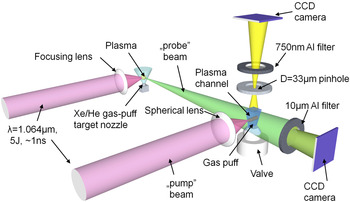
To form plasma channels we employed an experimental setup, depicted in Figure 1. Multistage Nd:YAG laser (model NL129 from Ekspla, Lithuania) delivers laser pulses with energy per pulse in range of 9.4–9.8 J, and full width half maximum (FWHM) time duration of 1.3 ns. The laser beam is split using a 50/50% beam splitter, producing two beams of equal energy ~5 J.
Experimental arrangement for generation of the plasma channels and their characterization using EUV and SXR radiation: NL129 laser beam is split into two beams: Pump and the beam that produces SXR probe beam. SXR beam used in shadowgraphy, whereas the EUV emission from the channel is investigated using a pinhole camera.

The first beam, called a pump beam, is focused using a spherical lens with a focal length of f = 250 mm. A single spherical lens, illuminated by the laser beam having 25 mm in diameter, produces Airy focal spot with the first lobe diameter equal to 26 μm at the focal plane of the lens. The focus is located 1.5 mm above a nozzle. The nozzle has a shape of a slit, 0.5 mm wide and 2 or 9 mm in length. The orientation of the nozzle is parallel to the pump beam. The nozzle is used to injects small amount of gas, into a vacuum chamber producing an elongated in shape krypton puff target. The target is irradiated with focused laser pulses. The flow of the gas is adjusted by an electromagnetic valve synchronized with the laser power supply. A synchronization pulse is generated always 1 ms before the laser pulse. A time delay (t delay) denotes a delay between arrival of the synchronization pulse and opening of the electromagnetic valve. Opening time (t open) is a time for which the valve is open. The delays are adjusted is such a way to have t delay+ t open = 1 ms.
The second beam, which might be delayed with respect to the first beam using a delay line, is focused using an f = 25 mm focal length spherical lens onto a second, xenon/helium double-stream gas puff target. Laser–pulse interaction with the gaseous target produces the xenon plasma. The plasma emits radiation in a broad range of wavelengths, including visible, EUV and SXR wavelengths. The details about characterization and optimization of the xenon/helium double-stream gas puff target were reported in (Fiedorowicz et al., Reference Fiedorowicz, Bartnik, Jarocki, Kostecki, Krzywiński, Mikołajczyk, Rakowski, Szczurek and Szczurek2005). The radiation from the plasma, which is called a probe beam, illuminates plasma channel, formed by the pump beam. The two beams are always perpendicular, as can be seen in Figure 1.
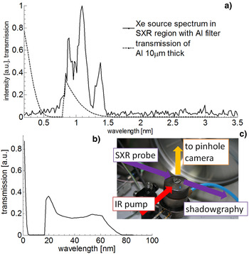
The probe beam is locally absorbed by the channel and spectrally filtered by a 10 μm thick aluminum filter. The filter selects radiation only from a narrow spectral range, between 8 and 15 Å – shown by dashed line in Figure 2a. The filtered radiation illuminates a detector – charge-coupled device (CCD) camera (M25 X-vision from Reflex, s.r.o, Czech Republic). The detector records projected images (shadowgraphs) of the plasma channel. A spectrum of the xenon plasma emission was measured using a transmission-grating spectrometer, equipped with a 200 nm period free standing grating and a CCD camera. The spectrum, obtained with the aluminum filter, is depicted in Figure 2a in solid line. The filter transmission curve was plotted based on data from CXRO database (http://henke.lbl.gov/optical_constants/). The data, presented here, were obtained for the delay between pump and probe beams equal to ~16 ns. More data at different delays 9, 16, and 23 ns, which led to measurements of the plasma expansion velocity, are reported in (Wachulak et al., Reference Wachulak, Bartnik, Jarocki, Fok, Węgrzyński, Kostecki, Szczurek, Jabczyński and Fiedorowicz2014).
Spectrum of the SXR probe beam, emitted from xenon plasma, used for shadowgraphy of the plasma channels (a). The radiation is spectrally narrowed using a 10 μm-thick aluminum filter. Transmission curves for a 10 μm thick (a) and 750 nm thick (b) aluminum filters are also presented. Detailed view of the gas puff target nozzle arrangement in parallel orientation of the nozzle with respect to the pump beam (c).

The plasma channel was also visualized using a pinhole camera, placed orthogonally to the pump and probe beams. For the measurements a laser drilled pinhole, ~30 μm in diameter, and a CCD camera, were used. To select EUV radiation, used to visualize the plasma channel in the wavelength range between 18 and 70 nm, an additional 750 nm-thick aluminum filter was placed between the pinhole and the camera, as can be seen in Figure 1 and in photograph in Figure 2c. The pinhole camera magnification was equal to 1.4. The transmission of the 750 nm-thick aluminum filter was depicted in Figure 2b.
3. EXPERIMENTAL RESULTS
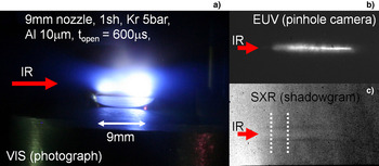
A comparison figure, depicting plasma channel formed in 9 mm long krypton gas puff target, is presented in Figure 3. Gas backing pressure was set to 5 bar and t open to 600 μs. One SXR pulse was required to obtain the images. Figure 3a shows elongated plasma channel recorded in the visible spectral range, using Canon EOS 350D digital camera. This channel was also visualized using a pinhole camera (Fig. 3b), and using shadowgraphy. Formation of the elongated plasma channel is very clear in all images, especially in Figure 3b. The channel visibility is reduced in Figure 3c because of presence of neutral krypton gas, surrounding the plasma channel, depicted schematically in Figure 1. This gas absorbs the probe beam; however, Figure 3c still gives good indication of the plasma channel width, measured here to be 0.65 mm, by averaging 20 adjacent vertical cross-sections, indicated by white dotted lines.
Comparison between images of the plasma channel, formed in a 9 mm long krypton gas puff target, as seen in various wavelength ranges: a photograph in the visible spectral range, a pinhole camera image in the EUV range and a shadowgraph in the SXR region. Images were acquired with a single laser pulse lasting ~1.3 ns.

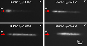
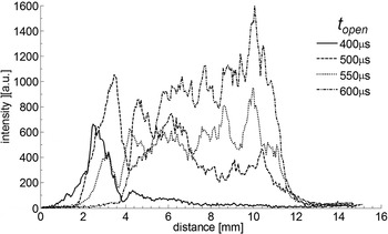
Depending on the t open time the length and uniformity of the plasma channel changes. This can be observed in the pinhole camera images, presented in Figure 4. The gas backing pressure was set to 5 bar and t open time varied between 400 and 600 μs. For t open = 400 μs, the channel is barely visible (Figure 4a). The most intense part of the channel emits EUV radiation only over approximately 1 mm length, closest to the point where the pumping beam starts interacting with the krypton target – front of the plasma channel. Shortest t open time indicates the lowest krypton gas puff target density. Increasing t open to 500 μs produces full-in-length and more uniform plasma channel, as shown in Figure 4b; however, the most intense region of the channel is still in the front of the plasma channel. The most uniform emission was achieved for t open = 550 μs, Figure 4c, however, peak emission is now shifted towards the end of the channel. This situation is even more pronounced in the last image in the sequence (Fig. 4d) for t open = 600 μs. Moreover, in this case the length of the channel is reduced to ~7 mm. Cross-sections obtained along the channel for various t open are presented in Figure 5. From the figure, the relative intensities of the EUV radiation emitted from the plasma channels can be compared.
Pinhole camera images of the plasma channels formed in the krypton gas puff target at gas backing pressure of 5 bar for various opening times of the valve (t open) for 400 μs – (a), 500 μs – (b), 550 μs – (c), and 600 μs – (d).

Longitudinal intensity profiles, obtained from the plasma channels from Figure 4, as a function of the distance, for various valve opening time (t open), showing optimal channel uniformity at t open = 550 μs.

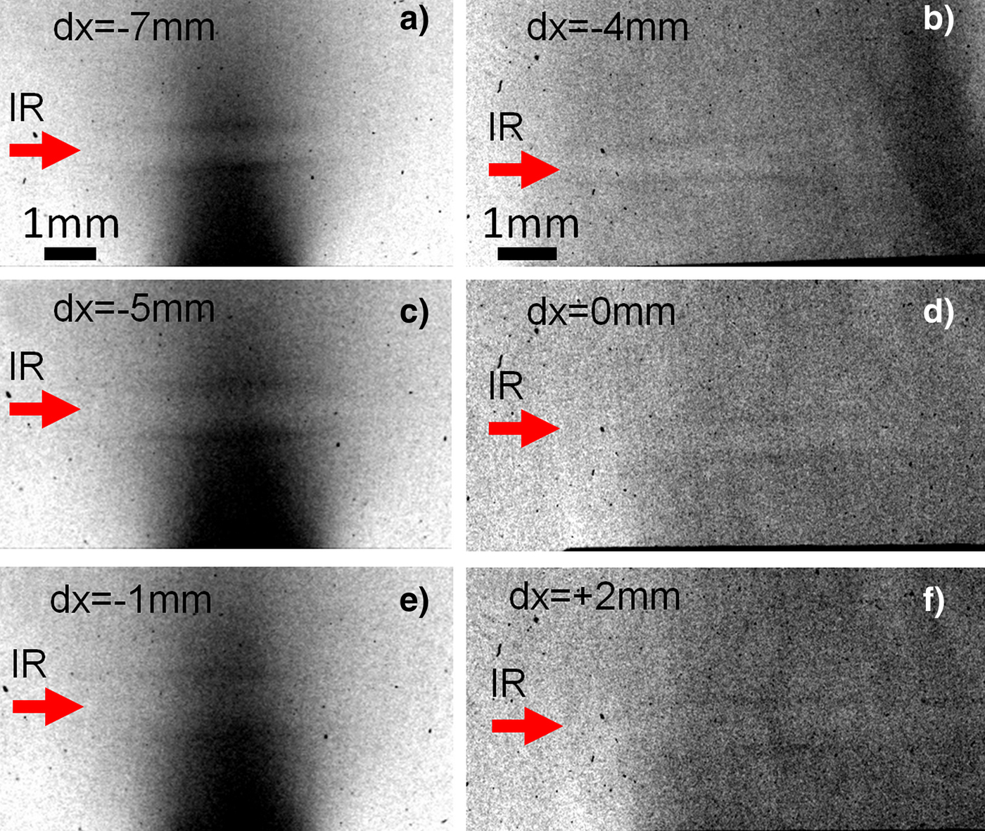
Shadowgraphs were acquired for various lengths of the nozzle and defocusing distances. All figures in Figure 6 have enhanced contrast to improve reduced plasma channel visibility. The channel visibility is reduced because of neutral krypton gas, which surrounds the plasma channel. This additional gas reabsorbs the probe beam. For 2 mm long nozzle a formation of horizontally aligned plasma channel is evident for defocusing distances equal to −7, −5, and −1 mm, corresponding to Figures 6a, 6c, 6e respectively. For these measurements the gas backing pressure was set to 5 bar and t open to 700 μs. The plasma channel appears wider in Figure 6e comparing with Figure 6a because of shifting of the position of the focal spot with respect to the nozzle. Similarly, for 9 mm long nozzle the plasma channel is also present, as can be observed in Figures 6b, 6d, 6f for defocusing equal to −4, 0, and 2 mm. In this case, the channel is much longer than before, so that the caustic of the beam can be noticed in the shadowgraph, depicted in Figure 6b. Moving the focus of the pump beam closer to the center of the nozzle, results in the channel that is more uniform across its length and slightly wider, as in Figure 6f.
Shadowgraphs depicting plasma channel formation in 2 mm (a, c, e) and 9 mm long (b, d, f) krypton gas puff target for various positions of the focal spot with respect to the nozzle (indicated in each figure). For 2 mm long target t open = 700 μs and for 9 mm long target t open = 500 μs, gas backing pressure was 5 bar.
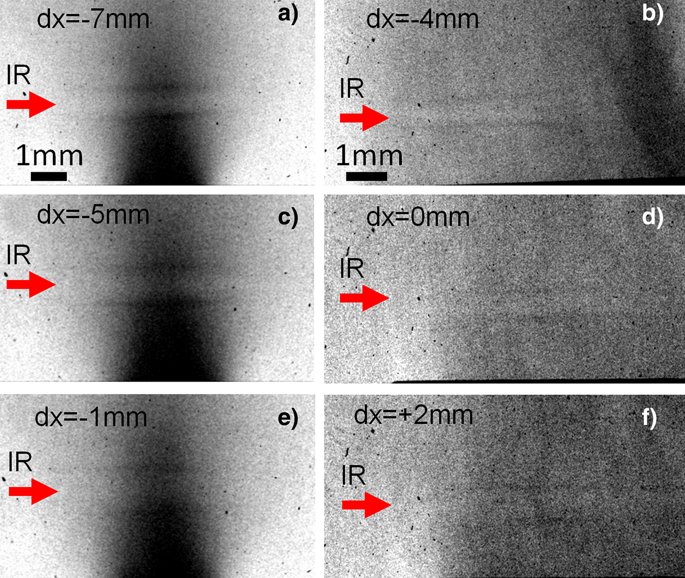
All shadowgraphs were acquired with a single, lasting ~1 ns, SXR pulse. Black region in the shadowgraphs, mostly visible in Figures 6a, 6c, 6e indicate increased krypton density near the exit plane of the nozzle. The plasma channel has high temperature along the axis of the spherical lens, which defines the direction of the plasma channel. This high temperature is responsible for strong EUV emission that was observed in Figure 4c and 4d in the pinhole camera images. After a short time, in the range of a few nanoseconds, because of temperature gradients and expansion of the ions from the axis, a “hollow” plasma density profile is produced. Expansion of the plasma results in formation of a cylindrical shock wave in the surrounding krypton gas. The dark lines in Figure 6 indicate projections of the cylindrical shockwave, expanding from the axis of the channel. In the shadowgraphs they appear as traces of increased density at the edge of the plasma channel.
4. SUMMARY
In summary, pump and probe experiments, related to plasma channel formation in the elongated, gas puff targets of various lengths, were presented. The plasma channel characterization in various wavelength ranges (visible, EUV, and SXR) and uniformity studies were presented. A 1 ns temporal resolution shadowgraphy and pinhole camera imaging were employed for plasma characterization. The imaging results show formation of a uniform cylindrical plasma channel with length limited by the length of gas puff target, in this case up to 9 mm. It was also concluded that the uniformity of the channels strongly depends on the opening time of the valve, which in turn is related to the target density.
ACKNOWLEDGMENTS
The research was supported by the Ministry of Science and Higher Education of Poland and the European Commission's Seventh Framework Program (LASERLAB-EUROPE – grant agreement 284464 and COST Action MP0601 and MP1203) European Economic Area (EEA) grants. PWW greatly acknowledges the support from the National Centre for Science, award number DEC-2011/03/D/ST2/00296 and the National Centre for Research and Development, Lider programme, award # LIDER/004/410/L-4/12/NCBR/2013.