


INTRODUCTION
With the development of chirped pulse amplification techniques, protons can be accelerated to very high energy in the interaction between ultra-short ultra-intense laser pulse and plasma targets. Above laser-plasma-based proton acceleration has been of great interests to many researchers due to its scientific, medical, and technical applications. For example, proton beams with high energy and low energy spread are essential for fast ignition in inertial confinement fusion (Roth et al., Reference Roth, Cowan, Key, Hatchett, Brown, Fountain, Johnson, Pennington, Snavely, Wilks, Yasuike, Ruhl, Pegoraro, Bulanov, Campbell, Perry and Powell2001), cancer therapy (Bulanov et al., Reference Bulanov, Esirkepov, Khoroshkov, Kuznetsov and Pegoraro2002), radiography (Borghesi et al., Reference Borghesi, Schiavi, Campbell, Haines, Willi, Mackinnon, Patel, Galimberti and Gizzi2003), future compact accelerators (Shearer et al., Reference Shearer, Garrison, Wong and Swain1973), and laser nuclear physics (Borghesi et al., Reference Borghesi, Fuchs, Bulanov, Mackinnon, Patel and Roth2006).
Originated in the last decade, when high energy protons were first found in ground breaking experiments (Clark et al., Reference Clark, Krushelnick, Davies, Zepf, Tatarakis, Beg, Machacek, Norreys, Santala, Watts and Dangor2000a; Maksimchuk et al., Reference Maksimchuk, Gu, Flippo and Umstadter2000; Snavely et al., Reference Snavely, Key, Hatchett, Cowan, Roth, Phillips, Stoyer, Henry, Sangster, Singh, Wilks, MacKinnon, Offenberger, Pennington, Yasuike, Langdon, Lasinski, Johnson, Perry and Campbell2000), a discussion about where these energetic protons originate from, has led to the introduction of the target-normal-sheath-acceleration (TNSA) (Wilks et al., Reference Wilks, Langdon, Cowan, Roth, Singh, Hatchett, Key, Pennington, MacKinnon and Snavely2001) mechanism. However, the energy spread of the proton beam in TNSA was relatively large. To limit the proton energy spread, the radiation pressure acceleration (RPA) mechanism (Esirkepov et al., Reference Esirkepov, Borghesi, Bulanov, Mourou and Tajima2004; Zhang et al., Reference Zhang, Shen, Li, Jin, Wang and Wen2007; Chen et al., Reference Chen, Pukhov, Sheng and Yan2008; Yan et al., Reference Yan, Lin, Sheng, Guo, Liu, Lu, Fang and Chen2008; Robinson et al., Reference Robinson, Zepf, Kar, Evans and Bellei2008; Qiao et al., Reference Qiao, Zepf, Borghesi and Geissler2009) has been proposed. Additionally, to accelerate protons to a much higher energy, some attention has been attracted to a combination of RPA and laser wakefield acceleration (LWFA) mechanisms (Shen et al., Reference Shen, Zhang, Sheng, Yu and Cary2009; Yu et al., Reference Yu, Xu, Wang, Sheng, Shen, Yu and Zhang2010; Zheng et al., Reference Zheng, Wang, Yan, Tajima, Yu and He2012). In the combined mechanism, the protons together with electrons in the overdense target are first pre-accelerated under the laser irradiation. As the laser pulse penetrates into the target and propagates through the underdense plasma gas, a fast-moving wakefield can be excited. Some pre-accelerated protons can be injected into the wakefield and further accelerated over a long distance to an extremely high energy. However, due to the difficulty in controlling the proton injection process, the energy spread of these ultra-energetic proton beams needs to be further reduced.
In this paper, an optimized scheme to reduce the energy spread of the proton beam generated by the combined proton acceleration mechanism is proposed by using a mixed hydrocarbon (CH) target to control the proton injection process, and is verified by a series of one-dimensional relativistic particle-in-cell (1D PIC) simulations. When the laser first irradiates the CH target, electrons are compressed at the front into a thin layer, behind which are the protons pulled by electrons; while the heavy carbon ions are left behind. Owing to the charge-separation effect and the Coulomb explosion effect (Brantov et al., Reference Brantov, Tikhonchuk, Klimo, Romanov, Ter-Avetisyan, Schnürer, Sokollik and Nickles2006; Liu et al., Reference Liu, Shao, Liu, He, Eliasson, Tripathi, Su, Wang and Chen2013) of the heavy ions, a large longitudinal electrostatic injection field with a negative gradient is formed, which will effectively further pre-accelerate and compress the protons, resulting in a large improvement of the proton injection process into the laser wakefield. After the improved LWFA, a monoenergetic, tens-of-GeV proton beam is generated. Additionally, for the first time, it is found that the proposed CH target optimization scheme in this combined mechanism can reduce the laser intensity needed to generate tens-of-GeV proton beams in contrast to the use of pure H targets.
SIMULATION MODEL
A multi-dimensional and explicit fully electromagnetic particle-in-cell (PIC) code with full relativistic plasma particle dynamics (named EXEMPLAR) is used to verify the proposed optimization scheme of proton acceleration based on the combined mechanism by using a mixed CH target. We use a circular polarized laser pulse with a wavelength λl = 1 µm and a temporal profile of the normalized laser amplitude a = eE l/m eωlc = a 0sin2(πt/τ), in which, e, E L, m e, ωl, and c are the electron charge, laser electric field, electron mass, laser frequency, and light speed, respectively. Here,  ${a_0}$ is the normalized peak laser amplitude, and τ = 25T l is the laser pulse duration, where T l = 2π/ωl is the laser period. A CH target, with thickness D = 1 µm and located at 0 < x < 1 µm, is chosen and assumed to be fully ionized as C6+ in such intense laser pulses. The electron density is n e = 15n c, where
 ${n_c} = {\rm \omega} _l^2 {m_e}/4{\rm \pi} {e^2}$ is the critical density for the corresponding incident laser pulse, with different ratios of the number density of C6+ in the CH target chosen, ranging from 0 to 90%. A tenuous tritium plasma, with a thickness L = 1000 µm and density n 0 = 0.1n c, is put behind the CH target. A 1200 µm long simulation box is constituted by 48000 cells along the x-direction. Each cell of the CH target is filled up with 3000 macroparticles and the tenuous plasma with 20 macroparticles. The initial electron temperature is 1 KeV.
Two-dimensional PIC simulations of such combined proton acceleration mechanism with RPA and LWFA have already been carried out (Yu et al., Reference Yu, Xu, Wang, Sheng, Shen, Yu and Zhang2010; Zheng et al., Reference Zheng, Wang, Yan, Tajima, Yu and He2012). The results prove that when considering multi-dimensional effects, this combined mechanism can also effectively accelerate protons to extremely high energy. Accordingly, here, attention is only concentrated on the improvement of the proton injection process when CH target is used and 1D PIC simulation results are presented to properly and clearly reveal the physical picture.
SIMULATION RESULTS
From a scaling study of the number density ratio of C6+ to H+, we find that the maximum energy of the proton beams is almost the same for different number density ratios for the CH case, when a 0 = 200. However, the beam size and the energy spread are improved as the percentage of number density of C6+ in the CH target increases. Here we first illustrate this improvement by comparing the result for one CH case (n i:n p = 9:1, where n i and n p are number density of C6+ and H+) and, for a pure H case (n i:n p = 0). In both cases, the tenuous plasma gases, located behind the overdense target, are the same, with the thickness L = 1000 µm and density n 0 = 0.1n c.
It is worth mentioning that the normalized laser intensity is intentionally chosen to be larger than the normalized areal density of the H target as 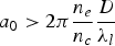 ${a_0} \gt 2{\rm \pi} \displaystyle{{{n_e}} \over {{n_c}}}\displaystyle{D \over {{{\rm \lambda} _l}}}$ in order to ensure that the target remains transparent to the laser pulse and that the wakefield in the underdense plasma gas can be excited. Under such laser intensity, the RPA mechanism starts to mix with other acceleration mechanisms, like breakout afterburner acceleration. However, the dominating mechanism is still RPA and protons can still be accelerated by the radiation pressure. Unlike the condition of the phase-stable scheme (Yan et al., Reference Yan, Lin, Sheng, Guo, Liu, Lu, Fang and Chen2008),
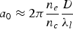 ${a_0} \approx 2{\rm \pi} \displaystyle{{{n_e}} \over {{n_c}}}\displaystyle{D \over {{{\rm \lambda} _l}}}$, where a stable double-layer structure of the electron and proton is formed to accelerate protons to high energy, the condition of our proposed optimization scheme of the combined mechanism relies on the wakefield (excited when the laser pulse propagates in the underdense plasma gas) to accelerate protons to extremely high energy. Consequently, the energy spread of the proton beams depends strongly on the proton injection process, which can be better controlled when a CH target is used.
Figure 1 shows the snapshots of the spatial distribution of densities at different times, as well as, the longitudinal electrostatic field. For the plots above (Figs. 1a, 1c, and 1e), a pure H target, with the same thickness, location, and electron density, is used to compare with the CH case below (Figs. 1b, 1d, and 1f). As is shown in the first column at t = 6T l, just before the laser penetrates into the target, the electrons are stably pushed by the non-oscillating ponderomotive force of the circular polarized laser and quickly piled up as a compressed layer at the laser front. In Figure 1a, the negative-gradient part of the charge-separation field only works on a small portion of the protons, bunching, and accelerating them; while the rest of the protons are under the positive-gradient part of the charge-separation field and debunched. However, in Figure 1b, because of the existence of the heavy carbon ions in the background, the bunching part of the charge-separation field is larger (Qiao et al., Reference Qiao, Geissler, Kar, Borghesi and Zepf2011a; Reference Qiao, Zepf, Gibbon, Borghesi, Dromey, Kar, Schreiber and Geissler2011b), and works on almost all of the protons, which results in a more stable pre-acceleration process.
Snapshots of the spatial distribution of densities (solid lines) and electrostatic field (dashed line) are shown for the H case (a, c, and e) and the CH case (b, d, and f) at 6, 12, and 700 laser periods, respectively. The initial parameters are as follows: for the H case, the proton density is n p1 = 15n c; for the CH case, the density ratio of C6+ to H+ is  ${n_i}\,\colon\, {n_{\,p2}} = 9\,\colon\, 1$. n 0 = 0.1n c is the electron density of the tenuous plasma located behind the overdense target.

More importantly, as is shown in the second column at t = 12T l, when the laser starts to propagate through the underdense plasma and excites a wakefield in it, a huge difference in the longitudinal electrostatic field between the CH target and the H target can be seen. As shown in Figure 1d, a large negative-gradient longitudinal electrostatic field is formed between an electron layer and the heavy carbon layer, due to the charge-separation and the Coulomb explosion effects. With its large negative-gradient, slower protons feel larger accelerating force while faster protons feel smaller one. And with its large amplitude, all protons will be accelerated to higher velocity. Thus, by moving together with the proton beam, this novel injection field can further pre-accelerate the protons to higher velocity and compress them as a narrow-structured sheet layer. As a result, we gain a better proton injection process in this combined proton acceleration mechanism by replacing the H target with the CH target.
Finally, in the LWFA stage, as is shown in the third column at t = 700T l, a narrow-structured proton beam with only 3 µm in size, is observed in Figure 1f. However, in Figure 1e, without the bunching effect of the injection field, the size of the proton beam is stretched to nearly 7 µm. To illustrate the bunching effect of the injection field more clearly, Figure 2 shows the evolution of the beam size for the H and CH case. It is shown that the size of the proton beam in the CH case is smaller than that in the H case, and the size of the proton beams stably stay around 3 µm in all CH cases. With a larger gradient of the wakefield and a more stretched structure of the injected proton layer, the debunching effect in H case is larger than that in the CH case. As a result, the size of proton beam in the H case grows faster than that in the CH case. Under the positive-gradient wakefield, this spatial difference will result in the difference in the energy spectra.
The size of proton beams at different times. The parameters for the plasma and laser pulse are the same as those given in Figure 1.
The energy phase space and the energy spectra of the proton beams are shown in Figure 3. For the CH case, as can be seen in Figure 3b, most of the protons have their energy larger than 60 GeV; while for the H case in Figure 3a, a large portion of protons has a lower energy. Specifically speaking, on the one hand, lots of protons from the H target have their energy lower than 5 GeV, which means they have not been injected into the wakefield. On the other hand, a large number of protons have the energy between 10 GeV and 60 GeV, which indicates that a certain amount of fast protons keeps dropping out of the wakefield during the LWFA process. Correspondingly, differences in the energy spectra are shown in Figure 3c and Figure 3d. Using the full-width at half-maximum (FWHM) to illustrate the energy spread, a nearly 3 µm proton beam gets a FWHM of less than 3% for the CH case. However, for the H case, the 17 µm proton beam has a FWHM of larger than 35%.
The phase space and the energy spectrum of the protons at 1000T l, where (a) and (c) are for H case, (b) and (d) are for CH case. In the phase space of protons, the x-axis is the proton position and the y-axis is the proton energy. In the energy spectrum, the x-axis is the proton energy and the y-axis is the proton number. The parameters for the plasma and laser pulse are the same as those given in Figure 1.
SCALING STUDY OF IMPORTANT PARAMETERS
To further optimize the combined mechanism for proton acceleration, the scaling of the number density ratio of CH and that of the laser intensity have been studied. The scaling study of number density ratio of CH is shown in Figure 4a. As the percentage of number density of C6+ increases, the size of the proton beams has been narrowed from 19 µm (no carbon) down to about 3 µm (90% carbon). At the same time, the corresponding energy spread of these beams illustrated by FWHM has also been reduced from 35% (no carbon) down to nearly 3% (90% carbon). These results can be explained from two aspects. From the first one, when the ratio of H+ decreases, the formation of the longitudinal electrostatic field becomes largely dependent on the heavy ions and electrons; while the protons are more like one component that just being accelerated by the field. In other words, the reduction reaction effect of the protons to the longitudinal electrostatic field will be constrained (as we can see from the 3rd column of Fig. 1, with the proton tail behind in Fig. 1e, the amplitude of the longitudinal electrostatic field is less than that of CH case in Fig. 1f) so that the energy spread will be reduced. From the second aspect, when the ratio of C6+ increases, the effect of the Coulomb explosion becomes larger, and the pushing effect of the heavy ions to the protons will be larger, too. As a result, the injection field becomes larger and wider, and its bunching effect is stronger, leading to a more compressed proton layer. With the size of the pre-accelerated proton beam being compressed, in the LWFA, the energy spread of this beam will be much less.
(a) The size and energy spread of the accelerated proton beams with the percentage of the carbon in the CH target. (b) The maximum energy that the pre-accelerated protons can achieve with the laser intensity. The data are counted at  $1000{T_l}$. All the other parameters are the same with those given in Figure 1.
Another scaling study of the laser intensity is shown in Figure 4b. When the laser intensity is relatively low, for example a 0 = 80 and a 0 = 120, the maximum energy of the protons in the H target is much smaller than those in the CH target, resulting from the fact that the acceleration mechanism for the H target is just RPA. This is because under the laser intensity condition of 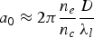 ${a_0} \approx 2{\rm \pi} \displaystyle{{{n_e}} \over {{n_c}}}\displaystyle{D \over {{{\rm \lambda} _l}}}$ (Yan et al., Reference Yan, Lin, Sheng, Guo, Liu, Lu, Fang and Chen2008), the laser pulse cannot penetrate through the H target. Instead, the laser field will stably push the overdense target as a double-layer structure, and the protons are accelerated by RPA mechanism. However, the laser can penetrate through CH target for a 0 = 80 and a 0 = 120 cases and the protons can be further accelerated by LWFA.
Figure 5 shows the snapshots of the spatial distribution of the laser field, the longitudinal electrostatic field and different kinds of densities at different times in the case of a 0 = 80. The plots (Figs. 5a, 5c, and 5e) are the pure H target case, while the plots (Figs. 5b, 5d, and 5f) are the CH target case. As Figure 5 shows, when a 0 = 80, the laser fields cannot penetrate through the pure H target. Instead, the protons and electrons are compressed as a double-layer structure, and it is pushed by the laser field and stably accelerated in the RPA mechanism. Moreover, with laser field co-moving with the double-layer structure, no wakefield is excited in the plasma gas region, thus no LWFA mechanism is involved in the acceleration process of this pure H case. However, the same laser fields can penetrate through the CH target, and excite a wakefield behind in the gas plasma region, and the protons are accelerated in the combined mechanism (RPA and LWFA). In fact, such difference comes from the balance between the forces of the laser pressure and the charge-separation field. When the target is mixed with high-Z components, the charge-separation field becomes lower. As a result, a lower intensity of the laser pulse is needed to balance the force of the charge-separation field, as compared with the pure H target. Therefore, the laser can penetrate through the CH target and excite the wakefield in the tenuous plasma. Thus, in contrast to the pure H case, protons in the CH target can experience a second stage acceleration in the wakefield and achieve a much higher energy.
Snapshots of the spatial distribution of densities (solid lines), longitudinal electrostatic field (blue dashed line) and laser field (green dashed line) are shown for the H case (a, c, and e) and the CH case (b, d, and f) at 6, 12, and 18 laser periods, respectively. The initial parameters are the same with those given in Figure 1 except that a 0 = 80, and  ${n_{eBP}} = {n_0} = 0.1$ is the electron density of the tenuous plasma,
 ${n_{eT}}$ is the electron density of the target,
 ${n_{iT}}$ is the carbon ion density of the target and
 ${E_y}$ is the y-component of the laser field.
As the intensity of the laser pulse increases to a 0 = 160, both of the two targets become transparent for laser pulses. However, without the heavy ions in the H case, protons are hard to inject into the wakefield. Consequently, the maximum proton energy in the H case is still smaller than that in the CH case. When we keep increasing the laser amplitude to a 0 = 200, even, a 0 = 240, the effect of the RPA stage will be large enough to inject the protons into the wakefields for both H and CH cases. Once the protons are captured by the wakefields, which have little difference in the peak amplitude (see from Figs. 1e and 1f), they will be accelerated to almost the same maximum energy.
In short, for the first time, by using the optimized CH target scheme, we can reduce the requirement for the laser intensity to get protons up to tens of GeV, as compared to the use of the H target in this combined mechanism. If our proposed optimization acceleration scheme is proved to be feasible, then, within the current laser sources, much higher proton energy can be achieved by using the CH targets.
CONCLUSION
In conclusion, an optimization of the proton acceleration scheme of the combined mechanism by using a CH target is proposed and verified by 1D PIC simulations. A strong longitudinal electrostatic injection field with a large negative gradient is formed due to the charge-separation and Coulomb explosion effects, because of the existence of the heavy ions. This novel injection field can largely improve the proton injection process into the wakefield by further pre-accelerating and compressing the protons. As a result, a contraction of the beam size and an improvement in the proton energy spread are achieved in the end. In addition, the scaling study of the laser intensity demonstrates that one can use CH targets to get much higher proton energy under the combined mechanism, by using a currently available laser sources, in comparison with the use of pure H targets.
ACKNOWLEDGEMENTS
The project was sponsored by the NSFC (Grants No. 11475029, No. 11375032, and No. 11175030), the Science and Technology Foundation of CAEP (Grant No. 2011A0102008), and the 973 project (Grant No.61319403). W. P. Yao would like to thank S. L. Yang and K. Q. Pan for valuable discussions.



