INTRODUCTION
Due to the development of chirped-pulse amplification technique, peta-watt short pulse lasers with intensity of 1022 W/cm2 are available in laboratories (Strickl & Mourou, Reference Strickl and Mourou1985; Perry et al., Reference Perry, Pennington, Stuart, Tietbohl, Britten, Brown, Herman, Golick, Kartz, Miller, Powell, Vergino and Yanovsky1999; Kienberger et al., Reference Kienberger, Hentschel, Uiberacker, Spielmann, Kitzler, Scrinzi, Wieland, Westerwalbesloh, Kleineberg, Heizmann, Drescher and Krausz2002; Ledingham et al., Reference Ledingham, McKenna and Singhal2003). Because of the high intensity of the laser field, there has been continuous interest in electron acceleration in vacuum and numerous theoretical and experimental studies (Barton & Alexander, Reference Barton and Alexander1989; Esarey et al., Reference Esarey, Sprangle and Krall1995a; Malka & Miquei, Reference Malka and Miquel1996, Malka et al., Reference Malka, Lefebvre and Miquel1997; Hafizi et al., Reference Hafizi, Ganguly, Ting, Moore and Sprangle1999; Stupakov & Zolotorev, Reference Stupakov and Zolotorev2000; Salamin & Keitel, Reference Salamin and Keitel2002; Salamin et al., Reference Salamin, Mocken and Keitel2003; Huang & Wu, Reference Huang and Wu2008; Schmid et al., Reference Schmid, Veisz, Tavella, Benavides, Tautz, Herrmann, Buck, Hidding, Marcinkevicius, Schramm, Geissler, Meyerter-Vehn, Habs and Krausz2009; Lourenco et al., Reference Lourenco, Kowarsch, Scheid and Wang2010; Smorenburg et al., Reference Smorenburg, Kamp, Geloni and Luiten2010; Xie et al., Reference Xie, Wang, Zheng, Zhang, Kong, Ho and Wang2010; Li et al., Reference Li, Fan, Zang and Tian2011) have been performed in this field. However, shortcomings of many of those schemes are that the electron energy spread and the space spread both in transverse and longitudinal directions are very large, especially using linearly polarized laser pulse. Because well-collimated electron beams are required in practical experiments, this limits the applications of those schemes.
It's well known that E z and β × B forces contribute significantly to the forward drift and to the rate at which electrons gain energy from the field. For linearly polarized Gaussian pulse, electrons are scattered at large angles and only a small portion can get very high energy. In this work, we propose a novel electron acceleration approach with two overlapping linearly polarized laser pulses in vacuum. The interfere of the two pulses at overlapping parts will produce an electromagnetic field that is totally different with the field of only one pulse. The dynamics of the electron and the acceleration process in this field will be affected. By numerical investigations, we found that our scheme can reduce the transverse scattering during acceleration, which leads to an extremely small space and energy spreads for the electron beam. Furthermore, for certain pulse lengths, average electron energy gained in such acceleration can be doubled comparing with acceleration using only one laser pulse having doubled peak laser intensity for realistic laser parameters.
MODEL AND METHOD
In our scheme, two overlapping pulses, pulse one and two are used to accelerate electrons initially at rest in vacuum. The two pulses are the same in their pulse lengths, wave lengths, waist sides, amplitudes, and polarizations. The relationship of the two pulses is that they are over lapping for δz and pulse two behinds pulse one, as shown in Figure 1. We use the Gaussian functions for the transverse directions for both pulses with the deviations 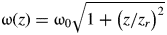 for pulse one, where ω0 is the waist size, z r is the Rayleigh length, z r = kω20/2 with k = 2π/λ and for pulse two w′(z) = w(z′), where z′ = z + δz. For the longitudinal shapes, cosine square forms are adopted instead of Gaussian ones (Esarey et al., Reference Esarey, Sprangle, Pilloff and Krall1995b; Hua et al., Reference Hua, Ho, Lin, Chen, Xie, Zhang, Yan and Xu2004; Karmakar & Pukhov, Reference Karmakar and Pukhov2007; Singh et al., Reference Singh, Sajal and Gupta2008). The cosine square forms satisfy the zeroth-order approximation for short laser pulse description for specific spectral distribution function, as Gaussian forms (Esarey et al., Reference Esarey, Sprangle, Pilloff and Krall1995b; Hua et al., Reference Hua, Ho, Lin, Chen, Xie, Zhang, Yan and Xu2004). In our simulation, we have selected linearly polarized Gaussian pulse because it is relatively easy to generate in the laboratory. The electric field of pulse one can be written as

where τp is full width at half maximum (FWHM) pulse length, c is the speed of light in vacuum, EG1 (r, t) is the electric field of Gaussian beam for pulse one. Substitute z with z′ we can obtain the electric field of pulse two

where EG2 (r,t) is electric field of Gaussian beam for pulse two. The total electric field will be presented by

The electric fields versus z at t = 0 and x = y = 0. E1 and E2 are the fields for pulse one and pulse two, and E is the total electric field.

Similarly, the magnetic field can be written as

where 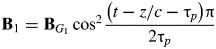 and
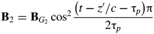 are magnetic fields for pulse one and two; BG 1, BG 2 are magnetic fields of Gaussian beams for pulse one and pulse two, respectively.
In our calculation, we use Gaussian pulses polarized along the x axis, propagating along the z axis, of wavelength λ, frequency ω and constant phase ψ0. The electromagnetic fields are calculated by Eqs. (3) and (4), and Gaussian field components EG1, EG2, and BG1, BG2 are given in Salamin and Keitel (Reference Salamin and Keitel2002) and expressed by
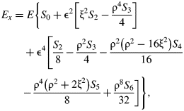

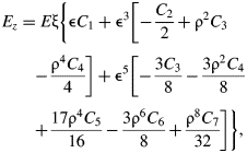

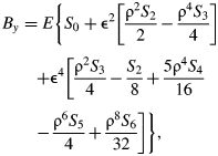
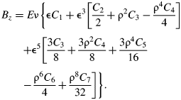
The paremeters used in Eqs. (5)–(10) are ξ = x/ω0, ν = y/ω0, ρ = r/ω0, ε = ω0/z r, r = (x 2 + y 2)1/2, 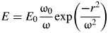 ,
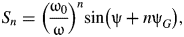 (n = 0, 1,…,6), and
 (n = 1, 2, …, 7). Also, E 0 = k A0, A 0 is the amplitude of a vector potential; ψ = ψ0 + ψP + ψG − ψR, where ψ0 is a constant phase, ψP = η= ωt − kz is the plane wave phase, ψG = tan−1(z/z r) is the Guoy phase, ψR = kr 2/(2R) is the phase associated with the curvature of the wave fronts, and R(z) = z + z 2r/z is the radius of curvature of a wave front intersecting the beam axis at the coordinate z. We can use the electromagnetic field expression directly for pulse one, and substituting z with z′ for pulse two. We use a dimensionless parameter (Salamin & Keitel, Reference Salamin and Keitel2002) q = eE 0/mcω in our work for convenience. The laser peak intensity I 0 is expressed in q by I 0 ≈ 1.375 × 10¹⁸q 2/λ2 (W/cm2), where wavelength λ is in μm.
We discuss the dynamics of electron by numerically solving the Newton-Lorentz equation
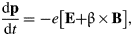
where, momentum p = γmcβ, the Lorentz factor γ = (1−β2)−0.5, β is velocity, normalized by the speed of light in vacuum. The energy gain is defined as (γ − γ0)mc 2, where the energy ɛ = γmc 2 can be obtained from dɛ/dt equation (Salamin & Keitel, Reference Salamin and Keitel2002)

RESULTS AND DISCUSSION
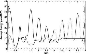
Firstly, we calculate the average energy gain of N = 13 electrons initially at rest and distributed along y axial from −0.5 ω0 to 0.46 ω0 with equal intervals of 0.08 ω0. The parameters of the laser pulses are chosen as wavelengths of 800 nm and FWHM pulse lengths of 8.5 fs, waist sizes 3 µm and peak intensities of ≈ 2.42 × 10²⁰ W/cm2 for the two pulses. The result is shown versus δz in Figure 2. There are several distinct regions where the average energy gains are comparable to or even larger than that at δz/λ = 0, corresponding to the one pulse acceleration. One can see that the average energy gain value is ≈ 64% larger at the point δz/λ = 3.5 than that at δz/λ = 0.
The average energy gain variation with δz with constant phase ψ0 = 0. The interaction time is 8.5 ps.

Figure 3 illustrates space spreads in x, y directions and Figure 4 electron energy gain spread variations with initial positions for δz/λ = 0, 1.0, 2.0, 2.5, 3.0 and 3.5. From Figure 3, it can be seen that space spreads at δz/λ = 2.5, 3.0, 3.5 are significantly small comparing with that at δz/λ = 0, and the spread reduces more than 85% in the y direction especially. From Figure 4, one can see that the energy gain spread reduces from ≈ 270% to ≈ 30% at δz/λ = 2.0, 2.5, 3.0, 3.5, about one-order-of-magnitude decrease.
Space spread in x-y directions for different δzs. Initial conditions are same for each δz and the interaction time is 8.5 ps.

Energy spread variations with initial positions for different δzs. Initial conditions are the same as Figure 3.

According to the Lawson-Woodward theorem, the net energy gain of a relativistic electron interacting with electromagnetic filed in vacuum is zero because in a plane wave every accelerating half cycle is followed by an equally decelerating one (Salamin & Keitel, Reference Salamin and Keitel2002). The Lawson-Woodward theorem conditions can not be satisfied in our investigation because the interaction is limited both in space and time for electron acceleration with the tightly focused laser pulse in vacuum and the non-linear effects are significant and cannot be neglected. In our simulation, the magnetic component of the Lorentz force β × B becomes comparable to the electric component E and the electron's velocity β initially acquired from E is modified by B. The electric component Ez and the Lorentz force component (β × B)z contribute significantly to the forward drift (see Eq. (11)) and the electron energy gain during the acceleration process is determined by Eq. (12).
Figure 5 shows examples of the energy gains versus election longitudinal position z using acceleration with (a) one pulse having doubled peak laser intensity, and (b) two overlapping pulses with a delay of 2.5 λ. The pulse length (FWHM) is 8.5 fs and the maximum accelerating field is about 4.26 × 10¹³ V/m, corresponding to the peak laser intensity ≈ 2.42 × 10²⁰ W/cm2, for our two pulse acceleration scheme in our calculation. From Figure 5a one can see that for electron acceleration with only one pulse, the accelerating lengths are about 30 and 300 µm in longitudinal direction for different electron initial positions in the example. And the electron undergoes several accelerating-decelerating phases and the main contribution to the final energy gain comes from the last accelerating phase. But the acceleration processes for different initial electron positions are quite distinct except in the early phases because the non-linear response to the laser field increases with the increasing of laser field amplitude. From Figure 5b , one can see that with our scheme the two acceleration processes for different initial electron positions are very similar to each other and the accelerating lengths are about 50 µm for two different electron initial positions and there is only one accelerating-decelerating phase for individual accelerating process. It can be understood as due to interacting with the overlapping part of the two delayed replicas of laser pulse the electron acquires it's initial velocity dramatically and drifts away from z-axis, which is different from acceleration with one pulse where the field amplitude increases from zero and the electron undergoes several accelerating–decelerating phases during the accelerating process. And we attribute the one-order-of-magnitude energy spread decrease to this difference between the two electron acceleration schemes.
Examples of the energy gains versus election longitudinal position z: (a) acceleration with only one pulse having doubled peak laser intensity, and (b) acceleration with the two pulse scheme with a delay of 2.5 λ. The solid and dash line stand for different initial position (0, −0.02 ω0, 0) and (0, −0.26 ω0, 0), respectively. Other parameters are the same as Figure 2.

Using numerical simulation, we tried to find analytical criteria for the optimal regimes. First, we investigate the effects of constant phase ψ0 when the other parameters keep unchanged. Figure 6 shows the average energy gains versus δz for ψ0 = π/2 (solid line) and π (dashed line). It must be noted that the curves are almost the same for ψ = 0 (Fig. 2) and π (Fig. 6, dashed line). One can see that the effects of constant phase ψ0 are obvious for fixed δz. But the maximum average energy gains for different ψ0 are affected slightly. The optimal δz changes linearly in one fourth wavelength when ψ0 changes in a period.
The average energy gain versus δz. Constant phase ψ0 is π/2 (solid line) and π (dashed line). Other parameters are the same as Figure 2.

In the following, we study the effects of pulse length τp. Figure 7 shows the energy gains versus δz for τp = 5 fs and 12 fs pulses. The interaction times are 5 ps and 12 ps, respectively. The interaction times are selected in our calculation to make sure the acceleration processes are finished. The maximum energy gain is gotten at δz/λ = 0 for τp = 5 fs, and local maximums at 1.5, 2.0, and 2.5. But the result is very different for the τp = 12 fs pulse (dashed line). The maximum energy gain is gotten at δz/λ = 4.5 and the average energy gained at 0 is less than one-half of the maxima. It means the acceleration efficiency is sufficiently increased with our scheme when the laser pulse duration is longer than several femtoseconds. But for extremely short pulse, our scheme loses effectiveness because the electromagnetic field of the laser pulse changes rapidly.

CONCLUSIONS
In summary, a novel electron acceleration scheme with two linearly polarized overlapping pulses in vacuum has been proposed and investigated numerically. According to our simulation results, smaller the energy and space spreads can be achieved with our acceleration scheme comparing with the one pulse acceleration scheme at the same conditions for realistic laser parameters. The constant phase affects the optimal region in one fourth wavelength and our scheme is more sufficient when the laser pulse lengths longer than several femtoseconds. We can draw the conclusion that our electron acceleration scheme has superiorities comparing with the scheme using only one pulse.
ACKNOWLEDGMENTS
This work was supported by National Natural Science Foundation of China (Grant No.11135002, 11075069, 91026021, 11075068 and 10975065), and the Fundamental Research Funds for the Central Universities (Grant No. lzujbky-2010-k08)