I. INTRODUCTION
The theory of adhesive contact between elastic bodies was first developed by Johnson, Kendall, and Robert,Reference Johnson, Kendall and Robert1 known as JKR theory, which is applicable to spherical indentation. KendallReference Kendall2 meanwhile analyzed the work of adhesion of a flat punch to a plane surface. While these studies dealt with short-ranged surface interaction inside a contact area, Derjaguin, Muller, and ToporovReference Derjaguin, Muller and Toporov3 used another approach known as DMT theory that considers long-ranged surface interaction only outside the contact area. TaborReference Tabor4 clarified two extreme theories: the JKR theory is adequate for compliant materials with high surface energy and large radius, and the DMT theory is appropriate for stiff materials with low surface energy and small radius. Most polymers are in the JKR regime. MaugisReference Maugis5 applied the Dugdale-type cohesive-zone model to analyze the transition between the JKR and DMT regimes. Following these pioneering works, many studies have investigated the adhesion energy of contacting elastic bodies (refer to the book by MaugisReference Maugis6 and the review by BarthelReference Barthel7 for details).
Adhesive contact between coated materials entails difficulties in obtaining the adhesion properties of the coating materials due to the effect of substrates. For example, if the JKR theory is used for spherical indentation onto an elastic film bonded to a substrate, only qualitative results are provided unless the film thickness is much larger than the contact radius of the spherical tip. Lebedev and UfliandReference Lebedev and Ufliand8 used the Henkel transform to solve the problem of pressing a rigid stamp of a circular cross section onto an elastic layer supported (i.e., not bonded) on a rigid substrate without friction. Their solution technique was extended to the problem of flat indentation on an elastic film perfectly bonded to an elastic substrate.Reference Lebedev and Ufliand8–Reference Choi, Lee and Earmme14 On the other hand, Mary et al.Reference Mary, Chateauminois and Fretigny15 developed a semianalytical approach to adhesive contacts between axisymmetric probes and layered substrates. Sridhar and coworkersReference Sridhar, Johnson and Fleck16–Reference Sridhar, Zheng and Johnson19 conducted numerical analyses with finite element method to take into account the effect of one or two compliant elastic coatings on adhesion between a sphere and an elastic solid. Also, Hayes et al.Reference Hayes, Keer, Herrmann and Mockros10and Yu et al.Reference Yu, Sanday and Rath11 analyzed spherical indentation onto an elastic film on a rigid or elastic substrate. Note that the JKR state of adhesive contact can be obtained by appropriately superposing the solutions of the flat indentation and the spherical indentation.Reference Johnson, Kendall and Robert1, Reference Maugis6 However, no analytic theory is available for adhesive contact of a spherical tip on an elastic film even though the solutions of the flat indentation and the spherical indentation onto an elastic film are known.Reference Hayes, Keer, Herrmann and Mockros10, Reference Yu, Sanday and Rath11
This article develops an extended JKR theory for adhesive contact of a rigid sphere onto an elastic film on a rigid substrate. Section II revisits an elasticity problem of axisymmetric indentation on an elastic film, in which the force–depth relations are obtained for both flat and spherical indentations in a simple form. With the obtained force–depth relations, Section III develops an extended JKR theory in which the energy release rate at the debonding of a spherical tip from an elastic film is obtained. The extended JKR theory developed in Section III is numerically studied and compared with the conventional JKR theory in Section IV. Finally, Section V concludes this study.
II. AXISYMMETRIC INDENTATION ON AN ELASTIC FILM
Consider the indentation problem in which a rigid axisymmetric tip is pushed onto an elastic film perfectly bonded to a semi-infinite rigid substrate. If the elastic modulus of the film material is much smaller than those of the indenter and the substrate, which is usually the case with polymer films, then the indenter and the substrate can be regarded as rigid bodies. Even though several researchersReference Lebedev and Ufliand8–Reference Choi, Lee and Earmme14 have studied analogous problems with some variations in tip geometries and boundary conditions, no solution is available for adhesive contact of a spherical tip on an elastic film. By solving the indentation problem, we can obtain the relation between the applied force and penetration depth, which is useful for studying the work of adhesion between a spherical tip and a film.
A. Axisymmetric indentation
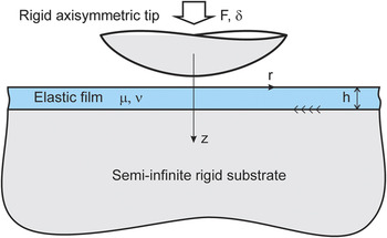
We consider the indentation of a rigid axisymmetric tip on an elastic film, as illustrated in Fig. 1. The interface between the film and the substrate is assumed to be perfectly bonded, while the contact between the indenter tip and the film is assumed to be frictionless. For the time being, no adhesion force is considered between the tip and the film. The cylindrical coordinate (r,θ,z) is used, as shown in Fig. 1, where the r axis lies on the free surface of the film, the z axis coincides with the axis of the cylindrical indenter tip, and θ is the angle between the r axis and a reference line from a point on the free surface of the film to the origin. The deformation of the film under a normal force F acting on the indenter tip is axially symmetric; hence, the nonzero displacement components u(r,z) in the r direction and w(r,z) in the z direction are independent of the angle θ and satisfy Navier’s equation, given asReference Gladwell20


Axisymmetric indentation on an elastic film bonded to a semi-infinite rigid substrate.

where ν is Poisson’s ratio of the film and the dilatation ε is given as
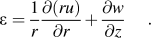
The dilatation ε is a harmonic function when the body force vanishes, so that
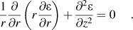
The boundary conditions on the free surface of the film are expressed as
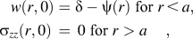

where δ, ψ(r), and a represent the penetration depth, the axisymmetric shape of the indenter tip, and the radius of contact region, respectively. Along the perfectly bonded interface between the film and substrate, the boundary conditions are given as

The solution procedure of the axisymmetric indentation problem described above was developed by several researchersReference Lebedev and Ufliand8–Reference Choi, Lee and Earmme14; thus, its details are not reproduced here, but its key results are summarized as follows.
The axisymmetric indentation problem can be converted into the following Fredholm integral equation of the second kindReference Choi, Lee and Earmme14:
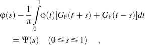
in which G F(t) is the Fourier cosine transform of G(λ), defined as
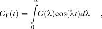
and

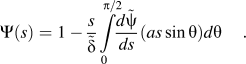
Note that every quantity of the length dimension is normalized by the contact radius a, and the tilt  is adopted to indicate the nondimensionalized quantity, e.g.,
 and
 . The integral equation (8) for φ(s) can be solved numerically for a given shape of the axisymmetric tip, i.e., the given shape function
 .
For a rigid flat tip,  . Thus, the integral equation (8) with Ψ(s) = 1 can be solved for φ(s), of which the solution is designated by φf(s). For a rigid spherical tip,
 , where R is the radius of the spherical tip. Thus,
 . The solution of the integral equation (8) can then be expressed as
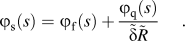
Here, φ f(s) is the solution for a flat tip, i.e., the solution to the integral equation (8) with Ψ(s) = 1, and φ q(s) satisfies
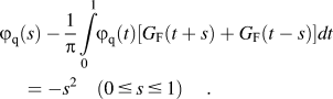
The continuity condition for the normal stress at the boundary of the contact area imposes a constraint on the solution given by Eq. (12)Reference Hayes, Keer, Herrmann and Mockros10:

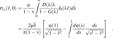
which provides the relation between the indentation depth δ and the radius a of contact area for spherical indentation. The normal stress underneath the indenter tip is given asReference Choi, Lee and Earmme14
B. Force–depth relation for flat indentation
Generally, in the indentation experiment, the relation between applied force and penetration depth provides critical information from which mechanical properties can be measured. For a flat circular indenter tip, integrating the normal stress distribution (as given in the above equation) over the contact area yields the contact forceReference Choi, Lee and Earmme14:
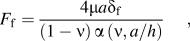
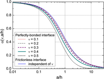
where the nondimensional parameter α(ν,a/h) is defined as
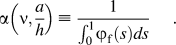
Here, φ f(s) is the solution of the integral equation (8) for Ψ(s) = 1. The force–depth relation given in Eq. (16) for the flat indentation on an elastic film perfectly bonded to a rigid substrate differs from that for the flat indentation on a semi-infinite elastic solidReference Sneddon21 only in the nondimensional multiplying factor α(ν,a/h). Note that the parameter α(ν,a/h), as well as φ f(s), depends only on Poisson’s ratio and a/h but not on the shear modulus of the film. The parameter α(ν,a/h) can be evaluated numerically by solving the integral equation (8) for Ψ(s) = 1, which is plotted against a/h for several values of Poisson’s ratio in Fig. 2. The value of α(ν,a/h) for the problem with a frictionless boundary condition between the film and substrate, as solved by Lebedev and Ufliand,Reference Lebedev and Ufliand8 is also plotted in Fig. 2 for comparison.
Plot of the nondimensional parameter α(ν,a/h) relating the applied force to the penetration depth of flat indentations on an elastic film for various Poisson’s ratios.Reference Choi, Lee and Earmme14 For comparison, the result for the frictionless interfaceReference Lebedev and Ufliand8 is also plotted.

C. Force–depth relation for spherical indentation
By solving the integral equation (8) with  and integrating the normal stress distribution given in Eq. (15) over the contact area, the force–depth relation for a spherical indentation is obtained as
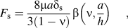
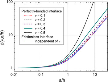
where the nondimensional parameter β(ν,a/h) is defined as
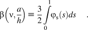
Here, φ s(s) is defined in Eq. (12) and can be obtained numerically. The parameter β(ν,a/h) is plotted against h/a for several values of Poisson’s ratio in Fig. 3. The value of β(ν,a/h) for the problem with a frictionless boundary condition between the film and substrate is also plotted in Fig. 3 for comparison. From Eq. (14), the relation between the contact radius and the penetration depth is obtained as
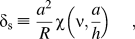
Plot of the nondimensional parameter β(ν,a/h) relating the applied force to the penetration depth of spherical indentations on an elastic film for various Poisson’s ratios.

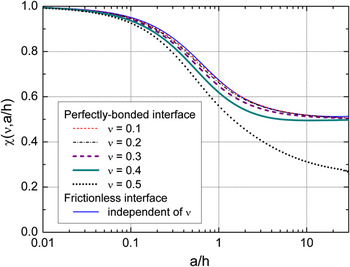
where the nondimensional parameter χ(ν,a/h) is defined as
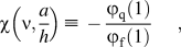
which is plotted against h/a for several values of Poisson’s ratio in Fig. 4. For mathematical simplicity, another nondimensional parameter is defined as

Plot of the nondimensional parameter χ(ν,a/h) relating the penetration depth to the radius of contact area of spherical indentations on an elastic film for various Poisson’s ratios.

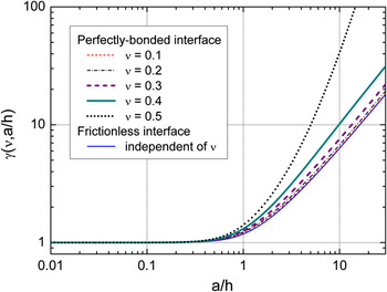
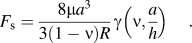
which is plotted against h/a for several values of Poisson’s ratio in Fig. 5. Combining Eqs. (18) and (20) and using the definition of γ(ν,a/h) given in Eq. (22) provide the relation between the applied force and the radius of the contact area:
Plot of the nondimensional parameter γ(ν,a/h) relating the applied force to the radius of contact area of spherical indentations on an elastic film for various Poisson’s ratios.

The relations given in Eqs. (18), (20), and (23) for the spherical indentation on an elastic film perfectly bonded to a rigid substrate differ from those for the spherical indentation on a semi-infinite elastic solid, known as the solution of Hertzian contact,Reference Hertz22 only in the nondimensional multiplying factors β(ν,a/h), χ(ν,a/h), and γ(ν,a/h), respectively. Note that the three nondimensional parameters depend only on Poisson’s ratio and the ratio a/h but not on the shear modulus of the film. As a/h approaches zero, the three parameters become unity; therefore, the relations in Eqs. (18), (20), and (23) become those of Hertzian contact.
III. EXTENSION OF THE JKR THEORY
In this section, the JKR theory is extended to the adhesive contact between a rigid sphere and an elastic film on a rigid substrate. Johnson et al.Reference Johnson, Kendall and Robert1 developed an equilibrium elastic theory of adhesion between elastic spheres. Maugis and BarquinsReference Maugis and Barquins23 and MaugisReference Maugis6 provided a detailed explanation of the same problem in the context of linear elastic fracture mechanics. The same procedure as illustrated in Section 4.5 of the book by MaugisReference Maugis6 is followed here to obtain the energy release rate at the debonding of a rigid sphere from an elastic film. Thus, by using the change of penetration depth given by Eq. (16), the penetration depth δ at the point B of Fig. 4.33 in the book by MaugisReference Maugis6 becomes

where the penetration depth δ s is given by Eq. (20).
The total potential energy in the system (with the axisymmetric tip replaced by a spherical tip) depicted in Fig. 1 is made up of three terms: the elastic energy U E stored in the elastic film, the work W = −Fδ done by the applied force F, and the surface energy U s = πa 2ω, where ω is the adhesion energy between the rigid sphere and the elastic film. The elastic energy U E stored in the elastic film becomes

The elastic energy release rate, the elastic energy recovered in a virtual decrease of the contact area, is given as
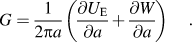
Note that Eq. (26) has the same meaning as Eq. (3.7) of MaugisReference Maugis6 (refer to Section 3.2 in the book by MaugisReference Maugis6 for more details). Differentiations of the elastic energy given in Eq. (25) and the work W = −Fδ done by the applied force F with respect to a yield
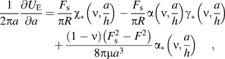
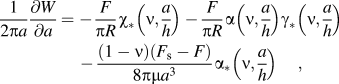
respectively. Here, the three nondimensional parameters α *(ν,a/h), χ *(ν,a/h), and γ *(ν,a/h) are defined as



Therefore, substituting Eqs. (27) and (28) into Eq. (26) provides the energy release rate as
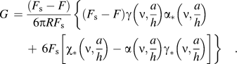
The energy release rate given in the above equation for the spherical indentation on an elastic film perfectly bonded to a rigid substrate differs from that of the JKR theory only in the nondimensional multiplying factors α(ν,a/h), χ *(ν,a/h), γ(ν,a/h), and γ *(ν,a/h). Note that the six nondimensional parameters α(ν,a/h), α *(ν,a/h), χ(ν,a/h), χ *(ν,a/h), γ(ν,a/h), and γ *(ν,a/h) are responsible for the discrepancy of the extended JKR theory from the conventional JKR theory. As a/h approaches zero, the effect of the rigid substrate disappears; thus, all six parameters become unity. The energy release rate given in Eq. (32) then becomes that of the conventional JKR theory.
IV. RESULTS AND DISCUSSION
In the previous section, the extended JKR theory was developed for adhesive contact of a rigid sphere onto an elastic film on a rigid substrate. In a load-controlled experiment, the critical energy release rate G cr at the instability of debonding equals the adhesion energy ω between the rigid sphere and the elastic film, i.e., G cr = ω. This critical energy release rate can be numerically obtained from Eq. (32). This section describes a method to evaluate the work of adhesion with the extended JKR theory.
A. Adhesion energy between a sphere and an elastic film
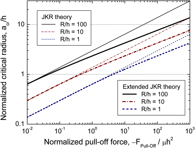
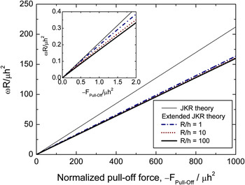
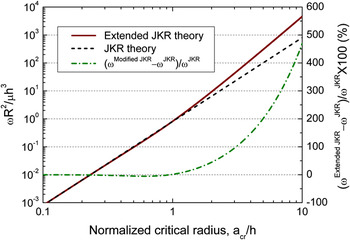
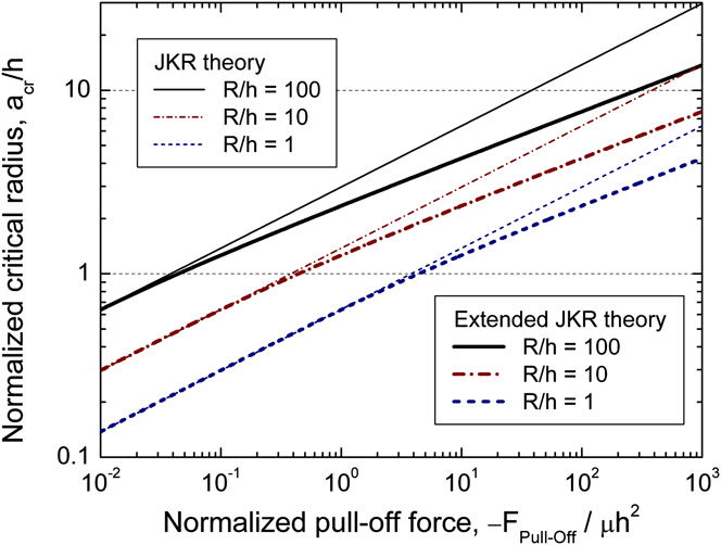
For simplicity of calculation, the Poisson’s ratio of the elastic film is assumed to be ν = 0.3. The approach described below can be applied with no difficulty for different values of the Poisson’s ratio. If the Poisson’s ratio ν, shear modulus μ, and thickness h of the elastic film and the radius R of the rigid sphere are known, then the energy release rate G is a function of only the radius of contact for a given force F. Note that F s in Eq. (32) can be expressed in terms of the radius of contact, as can be seen in Eq. (23). Therefore, the critical condition (∂G/∂a)F = 0 at the instability of debonding can be evaluated numerically to give the critical radius of contact, which is plotted against the normalized critical force (i.e., normalized pull-off force) in Fig. 6. By substituting the critical radius of contact into Eq. (32) and using the critical condition G cr = ω, the work of adhesion can be obtained in terms of the pull-off force or the critical radius, which are plotted in Figs. 7 and 8, respectively. The results of the conventional JKR theory referred to in Figs. 6–8 are calculated with the following relationsReference Johnson, Kendall and Robert1:


Critical contact radius at debonding as a function of the normalized pull-off force for ν = 0.3.
Adhesion energy as a function of the normalized pull-off force for ν = 0.3.

Adhesion energy as a function of the normalized critical radius of contact area for ν = 0.3.

Figure 6 shows that as a cr/h increases, the extended JKR theory deviates further from the conventional JKR theory, and the deviation starts around a cr/h = 1 regardless of the ratio R/h. That is, the rigid substrate affects the contact radius only if the contact radius is larger than the thickness of the film. However, when R/h = 1, a cr/h cannot be larger than 1; thus, the extended JKR theory gives almost the same results as the conventional JKR theory. For a given value of the measured pull-off force, the critical radius of contact for an elastic film is less than that for a semi-infinite solid due to the effect of the rigid substrate. Figure 7 shows the work of adhesion obtained from Eq. (32) when the pull-off force is assumed to be known. In the conventional JKR theory, the adhesion energy is proportional to the pull-off force. The extended JKR theory reveals similar results for different R/h ratios for relatively large values of the normalized pull-off force, −F Pull-Off/μh 2, as shown in Fig. 7. However, the normalized pull-off force has different effective ranges for different values of the ratio R/h. For example, the normalized pull-off force for R/h = 1 is always less than 3.8 from Fig. 6. In that range, for a given value of the normalized pull-off force, the adhesion energy according to the extended JKR theory is similar to that of the conventional JKR theory, as shown in the inset graph of Fig. 7.
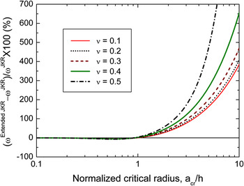
When ωR 2/μh 3 is plotted against the normalized critical radius a cr/h, the curves of ωR 2/μh 3 for different values of the ratio R/h merge into the one as shown in Fig. 8. The percent difference between ωR 2/μh 3 of the extended JKR theory and the conventional JKR theory is also plotted in Fig. 8, showing that the difference dramatically increases above a cr/h = 1. For example, when a cr/h = 3.08, the adhesion energy from the extended JKR theory is twice that from the JKR theory. By following the procedure given in this section for ν = 0.3, the percent difference of ωR 2/μh 3 between the extended JKR theory and the conventional JKR theory is plotted in Fig. 9 for various Poisson’s ratios. The percent difference dramatically increases above a cr/h = 1, and as the Poisson’s ratio of the elastic film increases, the percent difference also increases. By recalling that it is usually hard to measure the radius of contact, it is practically recommended that when the nondimensional parameter ωR 2/μh 3 is expected to be greater than unity, the extended JKR theory should be used in place of the conventional JKR theory to correctly estimate the adhesion energy. As an example, consider a polymer film with thickness of 1 μm, for which the shear modulus and Poisson’s ratio are assumed to be 500 MPa and 0.4, respectively. When the adhesion energy between the polymer film and the spherical tip with radius 100 μm is 200 mJ/m2, ωR 2/μh 3 = 4, and the conventional JKR theory may underestimate the adhesion energy to be 158.6 mJ/m2 (79.3% of the adhesion energy).
The percent difference of adhesion energies (ω Extended JKR−ω JKR)/ω JKR between the extended JKR theory and the conventional JKR theory as a function of normalized critical radius.

B. Discussion
The results presented in this study were obtained on the basis of several assumptions. First, the indenter tip and substrate are regarded as rigid bodies. This assumption is reasonable for most polymer films since the moduli of polymers are about hundred times lower than those of common substrates (Young’s moduli of polymers and silicon are normally 1–3 GPa and about 150 GPa, respectively). Second, the assumption that the interface between the film and substrate is perfectly bonded is suitable for most coated films. However, the assumption of frictionless contact between the tip and film is controversial. Although cohesion between the tip and film can resist shear loadings, this assumption does not lead to significant error since the traction vector acting on the contacted surface is mostly normal to the surface unless tangential loading is applied on the tip. Third, the response of polymers under applied loading usually involves not only elastic deformation but also viscoelastic or viscoplastic deformations, or both, depending on temperature and applied loading. Therefore, the material properties of polymers are typically treated as functions of time (or frequency) and temperature. Note that the energy release rate for an elastic film given in Eq. (32) is still valid for a viscoelastic film if viscoelastic losses are limited to a small process zone of debonding.Reference Maugis and Barquins23
Even though temperature is held constant, the elastic–viscoelastic correspondence principleReference Sridhar and Johnson18 cannot be applied to the elastic solution of the spherical indentation on an elastic film obtained in this study since the regions of prescribed boundary conditions vary with time. The exception is the case where the contact area is a monotonically increasing or decreasing function of time, and such cases have been extended to more general cases as discussed in the references cited in the book by Christensen.Reference Christensen24 Furthermore, if Poisson’s ratio is not a function of time, which is the common assumption for polymer materials, then the six parameters α(ν,a/h), α *(ν,a/h), χ(ν,a/h), χ *(ν,a/h), γ(ν,a/h), and γ *(ν,a/h) depend on time through the contact area a = a(t). The extended correspondence principleReference Graham25 can then be applied to obtain the viscoelastic solution of the spherical indentation on a viscoelastic film. This aspect requires further investigation.
V. CONCLUSION
The JKR theory was extended to adhesive contact of a rigid sphere onto an elastic film on a rigid substrate. An elasticity problem of axisymmetric indentation on an elastic film was revisited, in which the force–depth relations were obtained for both flat and spherical indentations in a simple form. With the obtained force–depth relations, the energy release rate at the debonding of a rigid sphere from an elastic film was expressed in terms of pull-off force, elastic constants, and geometric parameters. The energy release rate for an elastic film on a rigid substrate differs from that for a semi-infinite elastic solid only in the nondimensional multiplying factors depending on the Poisson’s ratio and the ratio of the radius of contact to the thickness of the film. The adhesion energy between the sphere and the elastic film can be measured as the critical energy release rate at the instability of debonding. If the critical radius of contact is larger than the thickness of an elastic film, the extended JKR theory should be adopted instead of the conventional JKR theory. Practically, it is recommended that when the nondimensional parameter ωR 2/μh 3 is expected to be greater than unity, the extended JKR theory should be used to correctly evaluate the adhesion energy between the spherical tip and the elastic film.
ACKNOWLEDGMENT
This work was supported by the 2011 Research Fund of University of Ulsan.